EP0269501B1 - Schleuderstreuer für körniges Material - Google Patents
Schleuderstreuer für körniges Material Download PDFInfo
- Publication number
- EP0269501B1 EP0269501B1 EP87402490A EP87402490A EP0269501B1 EP 0269501 B1 EP0269501 B1 EP 0269501B1 EP 87402490 A EP87402490 A EP 87402490A EP 87402490 A EP87402490 A EP 87402490A EP 0269501 B1 EP0269501 B1 EP 0269501B1
- Authority
- EP
- European Patent Office
- Prior art keywords
- rollers
- roller
- chute
- axis
- injection
- Prior art date
- Legal status (The legal status is an assumption and is not a legal conclusion. Google has not performed a legal analysis and makes no representation as to the accuracy of the status listed.)
- Expired - Lifetime
Links
- 238000002347 injection Methods 0.000 claims description 99
- 239000007924 injection Substances 0.000 claims description 99
- 238000009826 distribution Methods 0.000 claims description 93
- 238000003892 spreading Methods 0.000 claims description 76
- 238000011144 upstream manufacturing Methods 0.000 claims description 43
- 230000005540 biological transmission Effects 0.000 claims description 20
- 239000000463 material Substances 0.000 claims description 14
- 230000005484 gravity Effects 0.000 claims description 9
- 230000002093 peripheral effect Effects 0.000 claims description 7
- 230000009172 bursting Effects 0.000 claims description 6
- 238000005520 cutting process Methods 0.000 claims description 4
- 230000007423 decrease Effects 0.000 claims description 4
- 230000001419 dependent effect Effects 0.000 claims 2
- ZBMRKNMTMPPMMK-UHFFFAOYSA-N 2-amino-4-[hydroxy(methyl)phosphoryl]butanoic acid;azane Chemical compound [NH4+].CP(O)(=O)CCC(N)C([O-])=O ZBMRKNMTMPPMMK-UHFFFAOYSA-N 0.000 claims 1
- 238000005192 partition Methods 0.000 description 44
- 239000003337 fertilizer Substances 0.000 description 29
- 230000003247 decreasing effect Effects 0.000 description 8
- 230000002349 favourable effect Effects 0.000 description 8
- 230000001965 increasing effect Effects 0.000 description 8
- 238000011161 development Methods 0.000 description 7
- 230000008901 benefit Effects 0.000 description 6
- 230000002829 reductive effect Effects 0.000 description 6
- 239000002184 metal Substances 0.000 description 5
- 230000035939 shock Effects 0.000 description 5
- 238000000576 coating method Methods 0.000 description 4
- 238000013459 approach Methods 0.000 description 3
- 239000011248 coating agent Substances 0.000 description 3
- 238000006073 displacement reaction Methods 0.000 description 3
- 239000002245 particle Substances 0.000 description 3
- 239000002689 soil Substances 0.000 description 3
- 238000005507 spraying Methods 0.000 description 3
- 230000008030 elimination Effects 0.000 description 2
- 238000003379 elimination reaction Methods 0.000 description 2
- 239000003673 groundwater Substances 0.000 description 2
- 238000004519 manufacturing process Methods 0.000 description 2
- 230000000873 masking effect Effects 0.000 description 2
- 238000009304 pastoral farming Methods 0.000 description 2
- 239000007921 spray Substances 0.000 description 2
- 239000007858 starting material Substances 0.000 description 2
- 238000005452 bending Methods 0.000 description 1
- 238000005119 centrifugation Methods 0.000 description 1
- 238000010073 coating (rubber) Methods 0.000 description 1
- 230000000295 complement effect Effects 0.000 description 1
- 238000010276 construction Methods 0.000 description 1
- 230000000694 effects Effects 0.000 description 1
- 230000005489 elastic deformation Effects 0.000 description 1
- 238000007667 floating Methods 0.000 description 1
- 238000005194 fractionation Methods 0.000 description 1
- 239000008187 granular material Substances 0.000 description 1
- 239000004009 herbicide Substances 0.000 description 1
- 239000002917 insecticide Substances 0.000 description 1
- 230000001788 irregular Effects 0.000 description 1
- 230000000670 limiting effect Effects 0.000 description 1
- 238000012423 maintenance Methods 0.000 description 1
- 238000000034 method Methods 0.000 description 1
- 238000012986 modification Methods 0.000 description 1
- 230000004048 modification Effects 0.000 description 1
- 230000036961 partial effect Effects 0.000 description 1
- 230000000750 progressive effect Effects 0.000 description 1
- 238000000926 separation method Methods 0.000 description 1
- 238000009331 sowing Methods 0.000 description 1
- 238000001228 spectrum Methods 0.000 description 1
- 238000003860 storage Methods 0.000 description 1
- 238000004804 winding Methods 0.000 description 1
Images






Classifications
-
- B—PERFORMING OPERATIONS; TRANSPORTING
- B65—CONVEYING; PACKING; STORING; HANDLING THIN OR FILAMENTARY MATERIAL
- B65G—TRANSPORT OR STORAGE DEVICES, e.g. CONVEYORS FOR LOADING OR TIPPING, SHOP CONVEYOR SYSTEMS OR PNEUMATIC TUBE CONVEYORS
- B65G31/00—Mechanical throwing machines for articles or solid materials
- B65G31/04—Mechanical throwing machines for articles or solid materials comprising discs, drums, or like rotary impellers
-
- A—HUMAN NECESSITIES
- A01—AGRICULTURE; FORESTRY; ANIMAL HUSBANDRY; HUNTING; TRAPPING; FISHING
- A01C—PLANTING; SOWING; FERTILISING
- A01C17/00—Fertilisers or seeders with centrifugal wheels
- A01C17/003—Centrifugal throwing devices with a horizontal axis
Definitions
- the present invention relates to an agricultural spreading apparatus, also called a spreader hereinafter, which is intended for spreading by forced spraying of grain or granular products for the treatment of soils, such as fertilizers. , herbicides, insecticides, and which can also be used to sow seeds of small sizes, in a sowing method called "on the fly”.
- spreaders comprising: a supporting frame on which is mounted at least one member for transmitting a rotational movement which is intended to be coupled to a motor, a hopper, mounted on the chassis and intended to contain a load of granular products which can flow through at least one opening at the base of the hopper, means for speeding up and forcibly projecting the granular products, which are supported by the chassis and supplied with granular products from at least one opening in the base of the hopper, and means for distributing the projected granular products, said distribution means also being supported by the chassis, and wherein said speed setting and forced projection means are arranged in at least one launcher group, comprising a first roller mounted in rotation on the chassis around its substantially fixed axis and whose external lateral surface forms a first endless surface mobile delimiting, with a second mobile endless surface, a projection chute having an inlet and an outlet which are of gradually and respectively passing section and decreasing and increasing, at least one of the endless surfaces being positively driven from said
- the first roller is cylindrical and substantially horizontal axis
- the distribution means receives the granular material thrown out of the chute projection
- the second endless surface is defined by the external lateral surface of an endless belt, in the lower position, passing around a rear pulley coupled to a drive means, and a front pulley which is a simple return pulley, and the endless belt cooperates with the cylindrical roller in the upper position, and acting as a tension roller applied against the upper strand of the endless belt, between the front and rear pulleys.
- the position of the axes of rotation of the pulleys as well as the inclination of these axes relative to the axis of rotation of the cylindrical roller are adjustable, in order to ensure a good tension in the endless belt and a suitable orientation of its direction of scroll.
- the means for supplying material to be sprayed from the chute delimited between the roller and the endless belt can be a belt or chain conveyor device or a volumetric supply device, for example with a worm screw.
- the bearings in which the front pulley is rotatably mounted are fixed on a support which is itself pivotally mounted about an axis on the chassis, so that the position of the axis of rotation of the front pulley is adjustable on an arc of a circle, in order to adjust the angle of the tangent to the strip with respect to the horizontal, at the point of launching of the projected material.
- the adjustment of this angle therefore constitutes a first adjustment of the trajectory in a vertical plane, this adjustment affecting the distance at which the material is projected as well as the distribution spectrum of the granular products.
- the angle can be adjusted manually or using remote controlled hydraulic means.
- the distribution means consist of a fixed deflector ensuring the division of the outlet flow into several jets distributed or distributed in a vertical plane by means of a plurality of deflection fingers, in the form of elongated rectangular strips, arranged at different angles. in order to deflect the granular products leaving the projection chute between the cylindrical roller and the endless belt according to different trajectories distributed in the vertical plane.
- the spreader described in American patent 3,746,264 makes it possible to modify the angle of the tangent to the endless band, at the level of the ejection point, over the width of the deflection fingers as well as on the value of the associated deflection angles, that is to say the angles of inclination of the different deflection fingers on the direction of movement of the projected granular products, leaving the projection chute.
- any floating of the portion of the endless belt which carries the granular products beyond the pinching zone with the cylindrical roller gives a jet which is geometrically defined in an imprecise manner, and therefore more difficult to flourish with the precision required using a deflector.
- any deformed zone of the endless belt in particular an elongation over part of its width, produced during its partial winding around the cylindrical roller, a zone for entraining granular products over a thickness greater than for the rest of the endless band. This irregularity is at the origin of a projected sheet of granular product having a non-uniform thickness, which prevents a precise distribution of the granular products.
- the transverse bending of the endless belt when taking care of the granular products, already requires a delicate adjustment of the distribution deflector.
- the two endless moving surfaces, facing each other do not have identical trajectories (substantially rectilinear trajectory for the endless belt, and circular path for the roller) and are more or less deformed by the granular products compressed together, while they also have very different flexibility characteristics; it
- the jet of propelled granular products has an imprecise direction, which varies particularly as a function of the thickness of the sheet of compressed granular products. This constitutes a major difficulty in deflecting and developing with precision the jet of projected granular products, using a deflector.
- the device described in U.S. Patent No. 3,297,143 comprises two elements one of which has a shape very compliant drum, which deforms under the effect of the counter-element which consists of a series of non-cylindrical components .
- the grains are respected but there is not enough speed, although this occurs over a fairly large width of the periphery of the two elements.
- the invention relates to a spreader of granular products which is reliable, economical to build and maintain, which allows an excellent geometrical definition of the trajectories of the projected granular products. and the total coverage of the spreading width including the strip of land above which the spreader and the tractor carrying it or the trailer are moved.
- the spreader according to the invention is characterized in that the second mobile endless surface is also formed by the external lateral surface of a second roller, mounted in rotation on the chassis around its axis, and in a position such that the first and second rollers, at least one of which is provided with a peripheral coating of an elastically deformable material, are substantially tangent externally to each other, so that the granular products are projected out of the projection chute in a thin sheet centered on the tangent plane common to the two rollers.
- Such an embodiment has the important advantages that the two rollers cooperating to delimit the projection chute, guarantee an excellent geometric stability of the sheet projected in the tangent plane common to the two rollers, that is to say that the mean plane of the projected tablecloth, depending on its thickness, is pretended to coincide with the tangent plane common to the two rollers.
- the geometric definition of the projected ply is therefore much more precise when it results from the cooperation of two rollers than when it is ensured by the cooperation of a single cylindrical roller with an endless belt.
- an embodiment with two rollers according to the invention has the advantage of having fewer axes, therefore fewer bearings, does not require any belt tensioning element, and presents less risk of misalignment.
- Said speed setting and forced projection means are arranged in at least one launcher group, comprising a first roller mounted in rotation on the chassis around its fixed axis, and the external lateral surface of which forms a first mobile endless delimiting surface, with a second movable endless surface, a projection chute having an inlet and an outlet which are of progressively decreasing and decreasing and increasing passage cross-section.
- At least one of the endless surfaces is positively driven from said transmission member and constitutes a driving surface which drives the granular products introduced into the inlet of the projection chute to the outlet of the latter so that these products receive, between the two moving endless surfaces, a linear speed which ensures their projection.
- the second movable endless surface is also formed by the external lateral surface of a second roller rotatably mounted on the chassis around its axis and in a position such that the first roller and the second roller including at least one of the rollers is lined with a peripheral coating of an elastically deformable material, are substantially tangent externally to one another, so that the granular products are projected out of the projection chute into a thin sheet.
- the rollers are cylindrical rollers, the axes of which are substantially parallel to each other and preferably substantially horizontal.
- the spreader comprises means for injecting granular products into the projection chute of at least one group.
- these injection means comprising a chute injection, having an inlet and an outlet whose passage sections are progressively and respectively decreasing and increasing, and which is situated between the base of the hopper and the projection chute of each corresponding launcher group, and delimited by the lateral surfaces external of two cylindrical rollers substantially tangent externally to each other and mounted in rotation on the chassis, each around its axis substantially parallel to the axis of the second roller of each corresponding launcher group, at least one of the two rollers which delimit the injection chute being positively driven in rotation from the chassis transmission member, so as to constitute a driving roller, driving the granular products introduced from the base of the hopper into the inlet of the chute injection to the outlet of the latter by transmitting a linear speed to them such that the granular products leave the outlet of the injection chute in a thin sheet centered on the tangent
- This embodiment of the invention is very advantageous, because the prior setting in speed of the granular products in the injection means makes it possible to increase the pressure of supply of the projection chute with granular products, and therefore to ensure the setting in charge of a large flow by the two rollers delimiting the projection chute.
- the tangent plane common to the two rollers which delimit the injection chute is substantially perpendicular to the tangent plane common to the first and second rollers delimiting the projection chute of each corresponding launcher group.
- the advantageous combination of metering means, injection means and means for speeding up and projection makes it possible to take care of the greatest flow rates of granular products at the level of the projection chute.
- the first roller delimiting a projection chute supplied from an injection chute simultaneously constitutes one of the two rollers delimiting said chute. injection, the other being a third roller, and the axis of the first roller being located above the axis of the corresponding second roller, and preferably inside the axis of the latter by compared to the base of the hopper.
- each launching group comprises its own injection means, and the axis of its third roller is located inside the axis of the corresponding second roller, with respect to the base of the hopper, and at a level located between the levels of the axes of the first and second rollers of the launcher group corresponding, the roller (s) positively rotated from the chassis transmission member being, for each launcher group, either the first roller or the second and third rollers.
- the axes of the first and third rollers are substantially located in the same horizontal plane. , so that they delimit a substantially vertical injection chute, and the third roller simultaneously delimits, with a fourth cylindrical roller, also mounted in rotation on the chassis around its axis substantially parallel to the axes of the first, second and third rollers and located and below said horizontal plane, so that the third and fourth rollers are substantially tangent externally to one another, a second projection chute similar to that delimited between the first and second rollers, at least one of the third and fourth rollers being provided with a peripheral coating of an elastically deformable material, and the u n at least third and fourth rollers being positively driven in rotation from the chassis transmission member, so that the speed setting and forced projection means are arranged in two launching groups which have an injection chute common, which one includes the first and second rollers and the other the third and fourth rollers, and which each
- the second and fourth rollers and the two injection deflectors have the same axial dimension, which is half that of the first and third rollers and, on the one hand, the second and fourth rollers and, on the other hand, the two injection deflectors are offset axially with respect to each other substantially by the value of their axial dimension, so as to divide the sheet of granular products leaving the injection chute in two substantially equal portions, and to limit as much as possible the axial size of the second and fourth rollers.
- the distribution means can be of different types. If they are of the type in which they comprise, for at least one launching group, a distribution deflector, which divides the sheet of granular products leaving the corresponding projection chute into contiguous fractions of sheets which are deflected, in a perpendicular plane to the axes of the first and second rollers delimiting said projection chute, according to different trajectories having angular orientations which vary progressively between two extreme inclinations relative to the direction of movement of the sheet of granular products at the exit of said projection chute, as is already known from the aforementioned American patent, it is then advantageous that, according to characteristics specific to the invention, the distribution deflector has a continuous and curved deflection surface, with a concavity turned towards the axis of said second roller, and bounded between an edge upstream, having a practically zero inclination on the tangent plane common to the first and second rollers and substantially contained in said tangent plane, two lateral edges, and a
- this spreading width extends from the drop point of the granular products having followed a substantially free path from the exit of the projection chute to the drop point of the granular products having followed the most deviated trajectory and located under the spreader itself.
- the invention also proposes, according to its own characteristics, to use distribution means different which include, for at least one launcher group, a deflector for developing the projected ply of granular products in a non-vertical plane and substantially parallel to the axes of the rollers delimiting the corresponding projection chute.
- such a deflector has a bundle of deflection surfaces which are spaced from one another substantially in the direction of the axes of the rollers, substantially perpendicular to a plane parallel to said axes, and each curved between its upstream edge and its edge.
- each deflection surface has a flat upstream part, slightly inclined on the direction of flow of the sheet projected at the entrance to the passages, preferably at an angle of less than 10 °, and long enough for any the fraction of the sheet moving in said direction of flow and guided by said deflection surface, meets this upstream part of the latter before being deflected by a curved part of this deflection surface, so that the corresponding ply fraction is brought into contact with the deflection surface practically without rebound of the granular products on this surface.
- each deflection surface also has a flat downstream part, following a curved part, in order to determine the orientation of the trajectory of the fraction of the corresponding ply beyond the corresponding downstream edge.
- each curved passage is delimited by a channel having a bottom, two side walls facing each other, one of which is convex and the structure is concave and defines the deflection surface corresponding to said passage, each channel preferably being closed by an upper wall, facing the bottom.
- the bottoms of the channels consist of a single base plate
- the side walls of the channels are defined by the opposite faces of curved partitions fixed to the base plate perpendicularly to the latter
- any walls upper channels are formed by a single cover plate, so that the flourishing deflector has the appearance of a flat box, the internal volume of which is subdivided by partitions into curved and adjacent passage channels.
- the starter group with which such a spreading deflector is associated is a starter group disposed laterally on the spreader, so that the axes of its rollers are substantially parallel or slightly inclined in the direction of movement of the spreader, so that the corresponding launcher group is intended in particular for the lateral spreading of granular products, it is advantageous that all the deflection surfaces of the same blooming deflector have their concavity turned on the same side which is preferably the side opposite to the direction of movement of the spreader.
- the spreading deflector is combined with a launcher group arranged transversely with respect to the direction of movement of the spreader, that is to say so that the axes of its rollers are substantially perpendicular or strongly inclined on the direction of movement of the spreader, in order to ensure, in particular, spreading of the large products backwards and laterally on both sides, it is advantageous that all the deflection surfaces of the same deflector blooming form a substantially fan-shaped beam.
- the distribution means comprise, for at least one launcher group, a bundle of distribution tubes, having different lengths, the upstream end parts of which are adjacent to the others, have their axes substantially in the mean plane of the projected ply of granular products, according to its thickness, and parallel to the direction of movement of said projected ply, and divide the latter into contiguous fractions of ply which are each guided by the one of the tubes to its downstream end, offset substantially in the direction of movement of said projected ply, relative to the downstream ends of the other tubes.
- the distribution is therefore ensured by a set or bundle of tubes, of a type already known and used in spreaders with pneumatic transport of the material to be spread. If it is desired to spread over a localized area of the ground each fraction of ply channeled in one of the tubes, it is then advantageous to equip the downstream end of each tube with a deflector, for example deflecting the fraction of ply corresponding to the ground and / or to the rear.
- a dispersed distribution using such tubes is also possible if the downstream end of each tube is equipped with a spark gap, towards which the fraction of the web guided in the corresponding tube is directed and on which granular products of this fraction of the sheet rebounds before falling back to the ground.
- downstream end of the tubes For allow spreading along localized lines, it is also possible to equip the downstream end of the tubes with a flexible conduit directed towards the ground. As is also known in the sets of pneumatic transport tubes for spreaders, it is also possible that the downstream end of each tube is equipped with a dividing end piece, dividing the fraction of ply guided in the corresponding tube into two parts, each is distributed over one of two zones of the ground which are offset with respect to each other in the direction of movement of the projected sheet.
- At least one of the tubes of the bundle is bent over at least part of its length, so as to bring its downstream end closer to a vertical plane passing substantially through the base of the hopper spreader.
- the distribution means consist of a deflector with a continuous and curved deflection surface, or with a beam of curved deflection surface, or else a bundle of distribution tubes
- the metering means may include a volumetric distribution device, comprising at least one rotary member, driven in rotation in a fed gutter. in granular products by an opening at the base of the hopper, but it is also possible that the metering means comprise a movable valve and adjustable in position vis-à-vis of an edge of an opening defined at the base of the hopper, between said edge and part of the external lateral surface of one of the rollers of at least one corresponding launcher group, said roller projecting partially in the base of the hopper and ensuring, by its rotation, the direct drive of the granular products towards the corresponding launching group or groups.
- the metering means are also common to the two launching groups.
- the flow of the sheet of granular products supplying at least one launcher group from the hopper is limited between two lateral flaps, and that the spreader also comprises at least one shutter which, as well as at least one of the two lateral flaps , or mobile and adjustable in a direction substantially transverse to the flow of the supply ply, in order to define the width and / or the position relative to the rollers of the corresponding launcher group or groups.
- the spreader according to the invention may, as already mentioned above, comprise one or more launching groups, at least one of these launching groups being such that the axes of these rollers are substantially parallel to the direction of movement of the spreader, and / or at least one of these launching groups being such that the axes of these rollers are inclined in the direction of movement of the spreader and, in particular, substantially perpendicular to this direction of movement.
- the spreader according to the invention can also ensure the distribution of the granular products by different launching speeds, in which case the distribution means can be limited to means for varying or changing the speed of rotation of the roller or consist of characteristics particular structure or shape of the rollers, making it possible to give granular products different speeds.
- deflector distribution means can be combined with distribution means at different launch speeds.
- this type of spreader comprises several groups of adjacent launches, the first rollers of which have the same radius, arranged side by side and coaxial and the second rollers of which are also of the same radius arranged side by side and coaxial, the rollers of one of the two sets of adjacent rollers thus defined being driving rollers, driven in rotation at different speeds from one roll to another, while the rollers of the other set are each mounted for rotation around its axis and each driven by contact and friction from the corresponding drive roller, the means for distributing the granular products comprising in this case means for driving the drive rollers in rotation at said different speeds, so that more trajectories or shorter spans can be obtained thanks to these different speeds.
- each of the adjacent launching groups comprises an injection chute delimited between its first roller and a third roller of a set of rollers of the same radius, arranged side by side and coaxial, and each mounted idly in rotation around its axis.
- the means for driving the motor rollers in rotation comprise a set of stepped pulleys, of different diameters from one another, independent of each other and each secured in rotation to one of the shafts of a set of shafts tubular and coaxial transmission, each of which is integral in rotation with one respactivemant of the drive rollers, as well as a stepped drive pulley, integral in rotation with a drive shaft and connected to each of the return pulleys by a drive belt.
- the spreader according to the invention may also include, for at least one lancaur group, means for varying and / or adjusting the speed of rotation of at least one roller of the corresponding launcher group or groups, in order to modify the spreading width by modifying the tangential vitasse of the roller (s) and therefore the speed given to the grainy products.
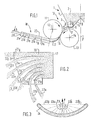
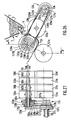
- the spreader shown in Figures 1 to 3 comprises a storage hopper 1, of a suitable capacity to ensure sufficient autonomy for the spreader during the working phase in a field, and which is mounted on a carrying frame (not shown) conveniently made like all chassis of agricultural machines, and movable behind a tractor.
- This chassis is equipped at the front with a hitching device of the well-known type called "three points" with hydraulic lifting, compatible with the hitching devices of agricultural tractors, when the spreader is intended to be carried to the rear of such a tractor.
- the carrying chassis is fitted with wheels for contact with the ground, and, at the front, a towing device for towing.
- a drive shaft intended to be coupled to a PTO of the tractor, is mounted in rotation on the chassis to ensure the rotational drive of the various rotary members of the spreader which will be presented below. .
- the hopper 1 contains a load 2 of granular products, for example fertilizers, which flows progressively through each of two lateral openings 3 (only one of which is visible in FIG. 1), arranged symmetrically in the base of the hopper 1, and each delimited between a side wall 4 of the hopper which is inclined towards the vertical, longitudinal and symmetrical plane P of the hopper 1 and of the spreader, and an inline flank of a bottom 5 whose cross section is shaped of inverted V and whose point is in the plane P.
- Each inclined blank of the bottom 5 ends, at the base of the hopper 1, by a rounded and slightly raised part in the shape of a gutter 6, which borders the lateral opening 3 and is extended outwards and downwards by a small flap 7.
- a volumetric distribution cylinder 8 is driven in rotation about a longitudinal and horizontal axis 9 and this cylinder 8 defines with the gutter 6 a fertilizer distribution channel. All of these elements constitute a metering and volumetric distribution device, ensuring the supply of granular products to a launcher group 10 described below.
- volumetric distribution device is meant a distribution device ensuring a supply of the products distributed regardless of the physical qualities of this product.
- the distributor cylinder 8 can be equipped with radial blades.
- the distribution cylinder 8 is positively driven in rotation, from the transmission mounted on the chassis, in a direction of rotation such that it drives in the corresponding distribution channel fertilizers which flow through the opening 3, according to a regular flow, and in a layer of fertilizer falling by gravity beyond the flap 7, towards the launcher group 10.
- This launcher group 10 comprises a first cylindrical roller 11 driven positively in rotation, in the same direction as the distributor cylinder 8, about its axis 12, which is fixed to the chassis and parallel to the axis 9, as well as a second cylindrical roller 13 mounted idly in rotation on the chassis around its axis 14, which is parallel to axes 12 and 9, and fixed, at a level lower than that of axis 12, itself below the level of the axis 9, the axis 14 also being inside the axis 12 relative to the plane P, but very slightly outside the axis 9.
- the axis 14 is positioned so that the two rollers 11 and 13 are very substantially tangent externally to each other.
- the outer lateral surface of the rollers 11 and 13 is provided with a peripheral rubber coating full with a hardness of 40 Shore, and therefore having elastic deformation properties on contact under pressure with the fertilizer grains.
- the rollers 11 and 13 are rotatably mounted on shafts (not shown), the two ends of which are received in bearings (also not shown) supported by the chassis.
- the two rollers 11 and 13 are substantially of the same diameter, and they delimit between them a projection chute whose inlet 15, of progressively decreasing passage section, is turned towards the metering and volumetric distribution device at the base of the hopper 1, while the outlet 16 of the chute, of progressively increasing passage cross-section, is directed towards the base and outwards, relative to the plane P.
- the layer of fertilizer distributed by the gutter 6 and the distributor cylinder 8 falls by gravity into the inlet 15 of the chute, and the relative positions of the axes 9, 12 and 14 are chosen so that the mean plane of this layer of fertilizer, depending on its thickness, is substantially coincident, when this sheet enters entry 15, with the tangent plane common to the two rollers 11 and 13.
- This layer of fertilizer is then taken up by the driving roller 11 which drives it towards exit 16 and the movement of the mass d 'in fertilizer is transmitted by friction to the lower rollers 13, which is thus rotated about its axis 14, in the opposite direction to the direction of rotation of the driving roller 11.
- the fertilizer table is thus pinched between the two rollers 11 and 13 , at the level of the contact generator of the latter, and, taking into account the high speed of rotation of the driving roller 11, driven from the transmission carried by the chassis, this roller 11 transfers to the passing fertilizer layer in the chute a sufficient linear speed so that at the outlet 16 of the chute, while the fertilizer layer is released from the grip of the rollers 11 and 13, its kinetic energy is such that the fertilizers are sprayed into a layer slim whose plan means, depending on its thickness, coincides with the tangent plane common to the two rollers 11 and 13.
- the latter thus constitute a device for speed setting and forced projection of a layer of fertilizer which, at its outlet 16 from the chute of projection, is received and deflected by a fixed slide 17.
- This slide 17, fixed to the chassis is a piece of curved sheet metal having its concavity turned towards the axis 12 of the upper roller 11, and the upstream edge of the slide 17, substantially parallel to the contact generator between the two rollers 11 and 13, is contained in a plane parallel to the tangent plane common to the two rollers but offset slightly towards the axis 14 of the roller 13, so that the projected sheet can, in the outlet 16 from the chute be received tangentially on the slide 17 and deflected by the latter progressively and without rebound of the fertilizers, therefore without bursting of the sheet to the downstream edge of the slide 17, at the nive in which the plane tangent to the latter is a plane parallel to the axes 12 and 14 of the rollers and inclined outwards and upwards, at an elevation angle favorable for obtaining the greatest span.
- this flourishing deflector 18 has substantially the shape of a flat box consisting of a base plate 19 and a cover plate 20, having the same substantially trapezoidal shape and parallel l 'to each other and to the plane tangent to the slide 17 at its downstream edge, and on either side of this tangent plane.
- the two plates 19 and 20 are held fixedly spaced from each other by a partition bundle 21a to 21g which are sheet metal plates perpendicular to the plates 19 and 20.
- the partition 21g towards the front of the spreader , is a flat partition closing the deflector box 18 forwards and substantially perpendicular to the axes 12 and 14 of the rollers 11 and 13.
- all the other partitions 21a to 21f are curved partitions having their concavity turned towards the rear of the spreader, on which the rollers 11 and 13 are mounted so that their axes 12 and 14 are substantially parallel to the direction of movement of the spreader.
- the average radii of curvature of the curved partitions progressively increase from the partition 21a to partition 21f: it is thus obtained that the blooming deflector 18 is subdivided between the two plates 19 and 20, into adjacent and curved passage channels, substantially divergent each of its entry, directly adjacent to the downstream edge of the slide 17, at its exit offset laterally and / or rearward.
- the shape of the partitions 21a to 21g of the bundle is such that the angles formed between the direction of the axes 12 and 14 of the two rollers and the planes tangent to the partitions 21a to 21g at their downstream edges are angles which gradually decrease from 90 °, for partition 21g to a negative value of approximately 20 ° for partition 21a.
- fractions 22d to 22g ensure a lateral distribution of fertilizers
- others, 22b and 22c provide a rearward distribution and that finally fraction 22a, and to a lesser extent, fraction 22b, also make it possible to distribute fertilizers on the strip of land above above which the tractor and the hopper and the launcher groups of the spreader are moved.
- the zone or soil on which the fertilizers are distributed is a zone 24 in the form of a curved rod which is delimited laterally by the fractions of transverse ply 22g and 22 ⁇ g not deviated by the deflectors, and, towards the rear, by the fractions of ply 22a and 22 ⁇ a most deviated, which approach towards the rear of the longitudinal median plane P at the point of substantially intersect in this plane P.
- the movement of the spreader 23 therefore makes it possible to cover a surface of land over a continuous spreading width, with a density of distribution of fertilizer which can be made uniform over the spreading width, or, on the contrary, follow a predetermined variation according to this width and possibly be grouped on several strips of non-adjacent land, separated from each other by strips on which no fertilizer is distributed, thanks to the choice of the number of deflection partitions 21, of the profile of their concave deflection surface, which deviates a fraction of corresponding ply, and therefore of the angles of the tangents to these cloissons at their downstream edge.
- each of the partitions 21a to 21f has a small upstream portion which is planar and perpendicular to the axes 12 and 14 and to the mean plane of the projected ply, at the passages of the downstream edge of the slide 17, and to this small upstream portion follows a more or less curved portion which extends to the downstream edge of the corresponding partition.
- This embodiment although satisfactory, is not the most favorable and can be advantageously replaced by that shown diagrammatically in plan in FIG. 4.
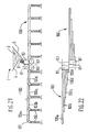
- FIG 4 there is shown in 19 ⁇ the base plate of the deflector on which are fixed the deflection partitions, only three of which have been shown in 21 ⁇ c, 21 ⁇ d and 21 ⁇ e.
- the upstream edges such as 25c to 25e of the partitions are regularly spaced from one another over the width of the projected sheet leaving the slide 17 by moving in the direction of the arrow F1, so that this projected sheet of fertilizer is divided in fractions of contiguous plies each having the same width l, equal to the ratio of the total width of the undivided ply to the number of intervals formed between the upstream edges of the partitions.
- Each partition has an upstream portion such as 26c to 26e, which is flat and slightly inclined in the direction of the arrow F1 (direction of the speed vector of the projected sheet) with a very small angle ⁇ , of the order of 5 ° , and this flat and slightly inclined upstream portion is long enough for the corresponding fraction of width l to have come over its entire width in contact with this upstream portion 26c to 26e, before the connection of the latter to a curved central portion 27c to 27th, ensuring the desired deviation of the groundwater fraction corresponding, and which is followed by a downstream portion, also flat, such as 28c to 28e, in the plane of which the fraction of corresponding ply freely continues its trajectory beyond the corresponding downstream edge, such as 29c to 29e.
- an upstream portion such as 26c to 26e, which is flat and slightly inclined in the direction of the arrow F1 (direction of the speed vector of the projected sheet) with a very small angle ⁇ , of the order of 5 ° , and this flat and slightly inclined upstream portion
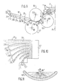
- the second example of a spreader is also a spreader with two lateral launching groups, with an axis parallel to the direction of movement of the spreader and symmetrically arranged with respect to the longitudinal and median plane P of the spreader.
- each launcher group 30, which consists of two rollers externally tangent to each other 31 and 33, mounted in rotation on the chassis respectively around their fixed axes 32 and 34, delimiting between them a projection chute, and cooperating with a slide 37, has substantially the same components having the same relative positions and operating in the same way as in the launcher group 10 of the spreader of Figures 1 to 3, so that it does is not necessary to describe it again in detail.
- This second example of a spreader is essentially distinguished from the first by the structure of the device for dosing the feed of the inlet 35 of the projection chute with granular products from the hopper 1, and by the structure of the distribution device. , mounted downstream of the slide 37.
- the metering device comprises a valve 39 in the form of a rectangular plate, slidably mounted by its short sides in two rails (not shown) fixed on the lower part of the outer face of the side wall 4 of the hopper 1, the valve 39 having its long sides parallel to the lower edge of this wall 4 and being adjustable in position relative to this edge of this wall 4, so as to delimit a lateral and rectangular opening for feeding granular products 2 from the inlet 35 of the projection chute, from the base of the hopper 1, this rectangular opening being delimited between the lower edge of the valve 39 and the part opposite the external lateral surface of the roller 33, the upper part protrudes into the hopper 1, between the side wall 4 and the bottom 5 of the latter.
- the roller positively driven from the transmission mounted on the chassis is the lower and internal roller 33, as can also be the case in the first example, and thus, in this second example, a direct drive is ensured.
- the supply flow rate of the projection chute is therefore proportional, for a given axial dimension of the device, on the one hand to the distance separating the roller 33 from the valve 39, adjustable in position in both directions of the double arrow F2 in FIG. 5 and, on the other hand, to the speed of rotation of the drive roller 33.
- the other essential difference of this second example compared to the first relates to the distribution device which, in this case, is a deflector 38 ensuring a development in the "vertical" plane of the fertilizer table projected and deflected by the slide 37
- This deflector 38 substantially of the type of that shown in FIG. 16 and described below in more detail with reference to the exemplary embodiment of FIGS. 12 to 16, is a piece of curved sheet metal, fixed to the chassis and of which the concavity is turned towards the base and towards the plane P of the spreader.
- the deflection surface of this deflector 38 is its concave face, which is continuous and curved substantially in an arc of a circle in a plane perpendicular to the axes 32 and 34, and this deflection surface is delimited between four edges, the upstream edge of which is substantially parallel to the downstream edge of the slide 37, therefore also to the axes 32 and 34 and situated in a plane parallel to the mean plane of the projected ply leaving the downstream edge of the slide 37, but slightly offset from the side of the axis 32 of the roller 31, so that the projected ply is received, throughout its thickness, on the deflection surface and approaches it substantially tangentially.
- the downstream edge of the deflector 38 is cut at an angle with its two lateral edges, so that the angle formed between the direction of the projected and deflected ply, at the outlet of the slide 37, and the tangent, in a perpendicular plane at axes 32 and 34, at the deflection surface and passing through a point in the cut of the downstream edge at an angle thereof, that is to say an angle which increases by practically zero, at a lateral edge 40 of the deflector 38 which is necessarily a small arcuate edge, up to a maximum value clearly greater than 90 °, at the level of the other lateral edge 41, which is a large arcuate edge of the deflector 38, so that the projected and continuous ply passing beyond the downstream edge of the slide 37 is divided into adjacent ply fractions of which that at the end of the ply running along the small lateral side 40 is only very little if not at all deflected, as indicated in 44a on the Figures 5 and 6, while the fracti one of the web of
- the ply fractions are gradually and continuously deflected by an angle which increases as one moves along the cut of the downstream edge 43 of the lateral edge 40 towards the lateral edge 41.
- the deflector 38 therefore allows the projection and distribution of the fertilizers as far as the machine, and the cutting profile of its downstream edge 43 can be adapted to the distribution on the ground with a spreading density desired. So that the entire projected ply leaving the slide 37 is supported by the deflector 38, it is more desirable that the upstream edge 42 of the deflector 38 is located substantially in the radial plane passing through the downstream edge of the slide 37.
- the deflector 38 for development in a vertical plane is of simpler structure than the deflector 18 for development in a "horizontal" plane of the previous example, because it only presents a single deflection surface.
- the deflector 38 will advantageously be used only for spreading granular products on fields in which the plantations have not yet been lifted.
- the spreader 38 gives a certain number of grazing paths which are likely to cause very significant shocks of the fertilizers on the vegetation, so that if the latter is already lifted, it is preferable to use in sectors d blooming in a "horizontal" plane, such as the deflector 18 of the previous example.
- FIGS. 7 and 8 schematically represent a third example of a spreader with two lateral launching groups, arranged symmetrically on either side of the longitudinal median plane P of the machine and each of which comprises only two axis rollers substantially parallel to the direction of the machine.
- this launcher group we thus find the upper and outer roller 11 and the lower and inner roller 13 already described in the first example, occupying the same positions relative to each other and cooperating in the same way in order to delimit between them a projectile chute, the latter being supplied with granular products 2 from the hopper 1 by a metering device which is a volumetric distribution device equivalent to that described with reference to FIG.
- ie -display comprising a pallet cylinder 48 driven in rotation in a lateral exit gutter of the hopper 1 and delimited between an upwardly rounded part 6 extending the bottom 5 of the hopper 1 and the lower edge of the side wall 4 of this hopper.
- This third example of a spreader is therefore distinguished from the first only by the structure of the distribution device. which includes, for each launcher group, a bundle 50 of distribution tubes, which are tubes similar to those used to transport the material to be spread in pneumatic spreaders.
- each bundle comprises six tubes of different lengths, five of which, the tubes 50a to 50e, of progressively decreasing lengths, are straight tubes mounted side by side while the sixth tube, the tube 50f, of the side of the rear of the spreader, is a tube bent in a horizontal plane and towards the rear, so that its downstream end is substantially in the vertical plane passing through the axis of the upper and outer roller 11 of the launcher group corresponding.
- the upstream ends 51 of the six tubes of each bundle 50 are directly adjacent to each other so that the axes of the upstream portions of the tubes are in the same plane, which is that of the mean plane of the projected ply and emerging from a slide 47 which guides the latter from the outlet of the projection chute corresponding to the inlet of the tube bundle.
- the axes of the upstream portions 51 of the tubes are perpendicular to the axes of the rolls 11 and 13 and therefore parallel to the direction of movement of the projected web and deflected by the slide 47, so that these upstream end portions 51 tubes divide this ply into contiguous ply fractions, each of which is guided by one of the tubes to its downstream end. Due to the differences in length of the tubes 50a to 50e and the curved shape of the tube 50f, the downstream ends of the tubes are distributed substantially regularly in a transverse direction relative to the movements of the spreader.
- each of the tubes of each bundle is equipped with a small deflector 52 which deflects the fraction of the sheet guided and transported downwards and, optionally, simultaneously or alternatively, backwards, direction of a spark gap 53, in the form of a curved sheet metal disc suspended in a manner fixed under the corresponding deflector 52, so that the fraction of the corresponding ply is deflected by the deflector 52 and directed by the latter on the corresponding spark gap 53, on which the corresponding fraction of ply is projected and bursts, by rebounds of the granular products , fall in a spray on the ground, around the spark gap 53.
- This embodiment guarantees precisely obtaining a spreading width, but the latter is significantly reduced compared to that which can be obtained with the first example of a spreader (see Figures 1 to 4), due to the dissipation of energy by friction in the transport tubes.
- the three examples of spreaders described above are more particularly intended for spreading products to be distributed with a low spreading density, and over relatively limited spreading widths, respectively due to the natural limitation of the flow rate.
- the spreader schematically represented in FIGS. 9 to 11 is also a spreader with two lateral launching groups arranged symmetrically on either side of the vertical median plane P of the apparatus, and each launching group cooperates with a distribution device which is a development deflector in the "horizontal" plane practically identical to the deflector 18 of the first example (see Figures 1 and 2).
- each launcher group is supplied from the hopper 1 by a metering device with volumetric distribution substantially identical to that of the first example, that is to say comprising a rotary vane cylinder 8 driven in rotation about its axis 9 , parallel to the direction of movement of the spreader and disposed in the gutter delimited between the lower edge of the side wall 4 of the hopper 1 and the part bent upwards 6 at the lower end of the bottom 5.
- a metering device with volumetric distribution substantially identical to that of the first example, that is to say comprising a rotary vane cylinder 8 driven in rotation about its axis 9 , parallel to the direction of movement of the spreader and disposed in the gutter delimited between the lower edge of the side wall 4 of the hopper 1 and the part bent upwards 6 at the lower end of the bottom 5.
- This example d The spreader therefore differs from the first example only in the production of each launcher group.
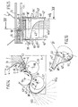
- This comprises three rollers, of which a first roller 55, in the upper position, is simultaneously tangent externally to a second roller 57, in the lower position and offset slightly towards the outside of the first roller 55 relative to the plane P, and to a third roller 59, offset towards the inside of the first roller 55 relative to the plane P and at an intermediate level between the first roller 55 and the second roller 57, these three rollers each being mounted in rotation respectively about their axis 56, 58 and 60, which are all three parallel to the axis 9 of the distributor cylinder 8 and to the direction of movement of the device.
- the first roller 55 is positively rotated from the transmission carried by the chassis, but as a variant, it is possible that the two rollers 57 and 59 are simultaneously positively rotated, the first roller 55 then being mounted for rotation about its axis.
- the relative positions of the axes 56, 58, 60 of the three rollers and of the metering device are chosen so that, on the one hand, the tangent plane common to the two rollers 55 and 57 is perpendicular to the tangent plane common to the two rollers 55 and 59 , and that, on the other hand, the granular products distributed by the metering device 8 fall by gravity into the inlet of the chute defined between the two rollers 55 and 59 in a continuous sheet whose mean plane, depending on its thickness, is practically coincident with the tangent plane common to these two rollers In other words, the speed vector of the feed flow from the chute between the rollers 55 and 59 is in the tangent plane common to these two rollers and in a direction perpendicular to their axes.
- the granular products falling into the inlet 62 of the chute between the rollers 55 and 59 are thus set in speed by the cooperation of these two rollers rotating at high speed and are projected in a sheet at the outlet 63 of this chute where this sheet setting in speed is taken care of without bursting, by approaching tangentially the upstream edge of a curved slide 61, with concavity turned towards the axis 56 of the first roller 55, and whose downstream edge is substantially parallel to the tangent plane common to both rollers 55 and 57, but slightly offset relative to this tangent plane on the side of the axis 58 of the roller 57.
- the roller 59 therefore constitutes an injection roller, cooperating with the first roller 55 to delimit an injection chute, the orientation of which is extremely favorable for good supply by the metering device, the injection device thus formed comprising also the injection slide 61 and the first roller 55 which, simultaneously, is a projection roller cooperating with the second roller 57 for delimiting the projection chute, the orientation of which is also very favorable for obtaining trajectories ensuring a large spreading width.
- the total coverage of this spreading width with a distribution density equal to the variables of the granular products from the most distant point to the plane P of the machine, is obtained by the interposition of the blooming deflector 18 ⁇ in the path of the tablecloth projected at the outlet 65 of the projection chute.
- the area 67 ⁇ is schematically represented, in the form of a curved rod, on which the granular products are distributed from the spreader, represented as a whole by the reference 68 ⁇ , and so that the displacement of the latter in the direction of arrow F covers a strip of surface on the ground.
- the shape of the zone 67 is substantially that of the zone 24 of FIG. 3, but its dimensions are greater.
- the fifth example of a spreader differs from that just described above only by the nature of the device for distribution associated with each of the two lateral launching groups, etc., incidentally, by complementary arrangements of the metering device, making it possible to selectively limit the width of the projected ply and therefore the value of the spreading width of the device.
- a launcher group comprising three rollers, the upper roller 55 of axis 56 delimiting with the lower roller 57 of axis 58 a projection chute and delimiting moreover, with the intermediate roller 59 of axis 60, a injection chute at the outlet of which the sheet speeded up between the rollers 55 and 59 is deflected and guided into the inlet of the projection chute by the slide 61.
- the upper roller 55 of axis 56 delimiting with the lower roller 57 of axis 58 a projection chute and delimiting moreover, with the intermediate roller 59 of axis 60, a injection chute at the outlet of which the sheet speeded up between the rollers 55 and 59 is deflected and guided into the inlet of the projection chute by the slide 61.
- the deflector 38 ⁇ is a piece of curved sheet metal, having the shape of a portion of cylinder delimited between two lateral edges 40 ⁇ and 41 ⁇ , curved in an arc of circle, a straight edge 42 ⁇ , along the generatrix of the cylinder, and which constitutes the upstream edge of the deflector, and a downstream edge 43 ⁇ in the form of a curved cutout between the downstream ends of the small lateral edge 40 ⁇ and the large lateral edge 41 ⁇ .
- the deflector 38 ⁇ is respectively adjacent to each of the flanges 62 ⁇ , and the upstream edge 42 ⁇ extends perpendicular to these two flanges and between them, being substantially contained in a plane parallel to the tangent plane common to the two rollers 55 and 57, therefore to the plane means, depending on its thickness, of the sheet projected by these rollers, but slightly offset with respect to this plane on the side of the axis 56 of the roller 55, so that, as in the example of the spreader in FIGS.
- the entire projected ply is taken care of by the upstream edge of the deflector 38 ⁇ substantially tangentially to the direction of movement of the ply, and therefore without bursting of this ply which is guided and gradually deflected by the deflector 38 ⁇ .
- the downstream edge 43 ⁇ of the latter formed by a cut whose shape progressively changes from one side edge to the other, is such that the angle formed between the tangent plane common to the two rollers 55 and 57 (containing the speed vector of the projected ply, which is perpendicular to the axes 56 and 58 of these rollers) and the tangent to the concave internal surface of the deflector 38 ⁇ , in a plane perpendicular to the axes 56 and 58 and passing through a point of the downstream edge 43 ⁇ , is a angle ⁇ which varies between 0 °, at the level of the small lateral edge 40 ⁇ , and 135 °, at the level of the large lateral edge 41 ⁇ , the variation of the angle between these two values being continuous, progressive, so that the deflector 38 ⁇ deflects , by its internal and concave deflection face, the projected ply leaving the projection chute between the rollers 55 and 57, dividing this ply into contiguous fractions deviated in a differential manner
- the fraction of ply 44 ⁇ a, supported by the deflector 38 ⁇ at its lateral edge 40 ⁇ , for which the angle between the tangent at the downstream edge 43 ⁇ and the tangent plane common to the two rollers 55 and 57 is zero follows a trajectory corresponding to the free trajectory of the projected granular products, which corresponds to the maximum spreading range, while the fraction of ply 44 ⁇ g, supported by the deflector 38 ⁇ at level of its large arcuate lateral edge 41 ⁇ , is deflected by an angle of 135 ° relative to its direction of movement at the outlet of the projection chute, so that this fraction of tablecloth 44 ⁇ g is directed under the spreader and towards the longitudinal median plane P of the latter.
- the other aquifer fractions are gradually deviated continuously by an increasing angle between these two extreme values, and follow trajectories allowing to reach points on the ground located between the outermost point, reached by the fraction of the tablecloth 44 ⁇ a, and the innermost point (towards the plane P), reached by the fraction of tablecloth 44 ⁇ g.
- oblong slots 67 formed in the deflector 38 ⁇ and allowing the passage and tightening of fixing nuts on legs (not shown) integral with the flanges 62 ⁇ , the oblong shape of the slots 67 also making it possible to modify the position of the deflector 38 ⁇ on the chassis substantially according to an overall rotation of the deflector 38 ⁇ around a geometric axis 58 ⁇ indicated on the Figure 14 as being substantially in the middle of a radius of the roller 57, this axis 58 ⁇ being the axis of curvature of the deflector 38 ⁇ .
- the deflection angle at any point on the downstream edge 43 ⁇ of the deflector 38 ⁇ corresponds to the angle at the center which underlies the arc of a circle delimited by the intersection of the internal and concave deflection surface of the deflector with the plane perpendicular to the axes of the rollers and passing through the point considered of the downstream edge 43 ⁇ , except at the level of the small lateral edge 40 ⁇ which is practically not arched.
- the total coverage of the spreading width is obtained by the interposition of the blooming deflector 38echer in the path of the sheet. of granular products, and, as in the example in FIG.
- the position of the projection rollers 55 and 57 determines the angle of the trajectory enabling the maximum range to be reached, and, which is the angle formed on the horizontal by the tangent plane common to the two projection rollers 55 and 57, this plane also being in this case perpendicular to the tangent plane common to the rollers 55 and 59 delimiting between them an injection chute in which the granular products, fed according to a sheet whose mean plane is substantially coincident with the tangent plane common to these two rollers 55 and 59, are set in speed and then guided by the injection slide 61 to the entrance of the projection chute.
- the entire width of the deflector 38l is used, between its lateral edges 40 ⁇ and 41 ⁇ , as shown in FIGS. 12 and 13. If you want distribute the granular products over a narrower spreading width, it then suffices to use the zone of the deflector 38 ⁇ whose angular cutout of the downstream edge 43 ⁇ corresponds to the desired trajectories, which is achieved, in this example by supplying granular products that this portion of the deflector 38 ⁇ , by masking part of the distribution, as shown in FIGS. 14 and 15.
- a metering device of the type ensuring a volumetric distribution, and essentially comprising a vane cylinder 8 driven positively in rotation in a gutter delimited laterally at the base of the hopper 1 between the lower edge of the has side wall 4 of this hopper and the rounded side part 6, with a flap of spill 7, from the bottom 5 of this hopper, so that the cylinder 8 and the rounded part 6 delimit between them a channel in which the granular products 2 are moved by the pallets driven by the cylinder 8 and discharged by gravity between the rollers 55 and 59.
- the sheet of granular products falling between the rollers 55 and 59 is laterally limited between two flaps 68 and 69, each in the shape of a very open V and arranged one opposite the other of so that they delimit a converging, one of the flaps 69 being fixed to the chassis and the other 68 slidingly mounted on this chassis along two longitudinal members 71 and 72 parallel to the axes of the rollers and to that of the cylinder 8.
- the lower parts of the flaps 68 and 69 extend against the flap 7 and the roller parts 55 and 59 facing each other.
- a shutter 70 in the form of a curved sheet engaged between the side wall 4 of the hopper and the pallets of the cylinder 8 until it comes in close proximity to the bottom 5 by its curved end with concavity turned towards the axis of the cylinder. 8, is also slidably mounted on the beams 71 and 72, and integral with the flap 68 moving along these beams. It therefore suffices to move the shutter 70 and the side flap 68 on the side members 71 and 72, for example by moving them towards the other fixed flap 69, from the position of FIG. 13, to partially close the opening , which, at the base of the hopper, allows the granular mass to flow towards the feed channel between the cylinder 8 and the rounded bottom 6.
- the fraction of ply 44 ⁇ d which corresponds to the edge of the ply reduced by half in width and having followed the movable flap 68, is deflected by an angle of approximately 45 ° relative to the tangent plane common to the two rollers 55 and 57 and in which the speed vector of the projected ply is located, at the level of its support by the upstream edge 42 ⁇ of the deflector 38 ⁇ .
- the side flap 69 is also a movable flap with a shutter similar to the shutter 70 and movable along the side members 71 and 72, so, by adjusting the relative positions of the two flaps 68 and 69 and the two corresponding shutters, to choose the part of the deflector 38 ⁇ which will be used to obtain the trajectories ensuring spreading on strips of land more or less close to the vertical and median plane P of the device.
- a small movable shutter and adjustable in position along the longitudinal members 71 and 72 independently of the flaps 68 and 69, it is also possible to split the supply sheet of the granular products into two non-adjacent parts, each of which is received.
- This embodiment therefore makes it possible to obtain all the desired spreading widths, within a maximum width determined by the tangent plane common to the two rollers 55 and 57, by limiting the supply to the zone or zones of the deflector 38 ⁇ which correspond to the chosen projection distance (s).
- a gearbox can also be mounted on the chassis, between the drive shafts 65 ⁇ and 66 ⁇ of the rollers 57 and 59, and also between the drive shaft of the pallet cylinder 8 on the one hand, and , on the other hand, the transmission intended to be coupled to the PTO of the tractor, so that the user can modify the speed of rotation of the rollers in order to modify the spreading width accordingly.
- the sixth exemplary embodiment is a spreader with two lateral launching groups, arranged symmetrically on either side of the median plane P of the apparatus, and each of the type consisting of three rollers, exactly as in the two examples previously described with reference to Figure 9 and Figures 12 to 15 respectively.
- Each of the two launching groups is supplied from the hopper 1 by a metering device identical to that shown in FIG. 9 or on Figures 12 to 15.
- each launcher group cooperates with a distribution device which, in this example, consists of a bundle 50 d'un of distribution tubes substantially identical to the bundle 50 of the example of Figures 7 and 8.
- the seventh example shown in FIG. 19, comprises two upper rollers 81 and 83, mounted in rotation on the chassis around their respective axes 82 and 84, parallel to each other and to the direction of movement of the device, and arranged in the same horizontal plane.
- These two upper rollers 81 and 83 are substantially tangent externally to one another in order to delimit between them a vertical injection chute, the outlet 92 of which is in the lower position and the inlet 91, of the upper position, is supplied in granular products 2 coming from the hopper 1 by a metering device with volumetric distribution identical to that equipping the embodiments of FIGS.
- the spreader has two lower rollers 85 and 87, rotatably mounted on the chassis each around its axis 86 and 88 respectively, which are parallel to the axes 82 and 84 also arranged in the same horizontal plane, the axis 86 however being outside the axis 82 of the roller 81 relative to the injection chute, while the axis 88 of the roller 87 is outside the axis 84 of the roller 83 relative to the same injection chute, the relative positions of the axes 86 and 88 relative to the axes 82 and 84 respectively being such that the lower roller 85 is substantially tangent to the outside of the roller 81 and delimits with the latter an inlet projection chute 93 and outlet 94, while the lower roller 87 is also substantially tangent externally to the upper roller 83 and delimits therewith a second inlet and outlet projection chute 95.
- the common tangent planes on the one hand the rollers 81 and 85 and, on the other hand, the rollers 83 and 87, and which correspond to the mean plane according to their thickness, of the plies projected out of the corresponding projection spouts, are planes inclined outward and upward relative to the vertical plane of the injection chute 91-92. These orientations are therefore very favorable for obtaining trajectories ensuring maximum range.
- the two upper rollers 81 and 83 have the same axial dimension, which is twice that of the two lower rollers 85 and 87, which are axially offset from one another by a distance substantially equal to their own dimensions. axial.
- the spreader has plus two injection slides 89 and 90, which are similar to the injection slide 61 of the examples in FIGS. 9 and 12.
- the two injection slides 89 and 90 are adjacent to each other in a vertical plane and transverse, and they are therefore offset axially to the same extent as the lower rollers 85 and 87, so that the slide 89, with a concavity turned towards the axis 82 of the upper roller 81, ensures by its upstream edge, a grip load at the outlet 92 of the injection chute with half of the sheet of granular products put in speed in the latter and guides and deflects it until injecting it tangentially into the inlet 93 of the projection chute between the rollers 81 and 85, and at the outlet from which, in 94, this half of injected and projected ply is taken up by a blooming deflector 18 ⁇ identical to that used in the example of FIG. 9.
- the other injection slide 90 takes care tangentially, in the outlet 92 of the injection chute, the other half of the sheet of granular products put in speed in this chute, and guides and deflects this half of the ply which is tangentially injected into the inlet 95 of the projection chute between the rollers 83 and 87, this half of the injected and projected ply then being taken up tangentially by another blooming deflector 18 ⁇ , the structure and the operation will not be described again.
- Two lateral launching groups are thus produced combined with a common injection chute supplied by a common metering device.
- the sheet put into gear in the injection chute is then divided into two parts, each of which is projected out of one of the two projection chutes and then distributed laterally, on one of the sides of the spreader, by a deflector of development in a "horizontal" plane.
- the vertical size of the embodiment of Figure 19 is greater, but it allows to benefit from a loading height, between the outlet of the gutter 6 and the central part of the injection chute 91-92, which is important , so that the pressure for handling granular products in this chute is high, which ensures high flow rates.
- Figure 19 is more economical than those of Figures 9, 12 to 15 and 17, because it has only four rollers instead of six and a single metering device instead of two.
- this embodiment is only advantageous for ensuring spreading over relatively reduced widths.
- the constraints which guide the choice of the roller or rollers which must or must be positively driven in rotation from the PTO of the tractor are that at least one of the two rollers which come first in contact with granular products, especially in an injection chute, must be positively driven to ensure the flow of granular products.
- at least one of the two rollers which are the last in contact with the granular products, in all cases at the level of the projection chute, must be positively driven to guarantee the launch speed and therefore the width of spreading.
- the positively driven rollers can be rollers 81 and 83, or rollers 81 and 87, or rollers 83 and 85. In these three cases, the other two rollers are mounted idly rotating around their axes and driven by friction and through granular products.
- the eighth exemplary embodiment, represented in FIG. 20, is not distinguished from the one just described. as by the nature of the distribution device associated with each of the two pairs of rollers delimiting one of the two projection chutes. Indeed, there are the four rollers 81, 83, 85 and 87, delimiting, by the two upper rollers 81, 83, the common injection chute 91-92, and, between each of the two lower rollers 85 and 87, and corrspondant upper rollers 81 or 83, a projection chute into which half of the web speeded up between the two upper rollers is injected using one of the two injection slides 89 and 90. There is also a single device dosing with volumetric distribution.
- each of the two "horizontal" blooming deflectors 18 ⁇ in FIG. 19 has been replaced by a blooming deflector 38 ′ in the vertical direction, of structure and functioning completely identical to that shown in the figure 16 and equipping the spreader of FIGS. 12 to 15.
- the cooperation of the rollers 81 and 85 with the associated deflector 38 ⁇ is the same as that of the rollers 55 and 57 with the corresponding deflector 38 ⁇ in the example of figure 12 to 15.
- the ninth exemplary embodiment also comprises four rollers mounted and cooperating as in the embodiments in FIGS. 19 and 20, to delimit two projection spouts and a single injection spout supplied by a single device dosage.
- the same reference numbers are therefore used to designate the equivalent elements.
- the distribution devices mounted on each side of the spreader, each consist of a bundle 100 of distribution tubes similar to the bundles 50 and 50 ⁇ of the exemplary embodiments of FIGS. 7 and 17. However, each bundle 100 consists only of five rectilinear tubes, of different lengths, 100a to 100e, and does not have tubes bent backwards.
- Upstream ends 101 of the tubes of each bundle 100 are adjacent, directly opposite the outlet of the corresponding projection chute and perpendicular to the axes of the rollers delimiting this chute. Due to the axial offset of the two lower rollers 85 and 87, the two beams 100 are also axially offset by the same distance.
- the downstream end of each of the tubes is shaped as a tip 101 curved downward and extended by a substantially vertical flexible conduit 102, so that the bundles of tubes 100 allow spreading in localized lines parallel to the direction of movement of the spreader.
- FIGS. 23 to 25 schematically represent a final example of a spreader, of simplified structure and of the so-called "transverse" type, since it is equipped with a launcher group whose rollers have axes 122 and 124 perpendicular to the direction of displacement of the spreader, indicated by arrow F in Figures 23 and 25.
- the launcher group consists only of the upper roller 120 and the lower roller 121, mounted in rotation on the chassis around their parallel axes 122 and 124 which are contained substantially in the same vertical plane, and a single roller is positively driven in rotation.
- the two rollers externally tangent to one another, thus delimit a substantially horizontal projection chute, supplied with granular products 2 coming from the hopper 1 in the same way as in certain previous examples, that is to say by a metering device with volumetric distribution cylinder 8 provided with pallets and cooperating with the gutter 6 of the bottom 5 of the hopper, the discharge flap 7 forming an injection slide in the chute.
- the output of the latter opens directly opposite a fan-shaped deflector 125 in a substantially "horizontal" plane.
- This deflector 125 is analogous to the deflectors 18 and 18 ⁇ of FIGS. 2, 11 and 19 in that it consists, between a base plate 127 and a cover plate 126, parallel to one another, of a bundle of adjacent and curved channels, delimited by curved and nonadjacent partitions, perpendicular to the plates 126 and 127, and the upstream ends of which are parallel to the direction of movement of the projected sheet leaving the projection chute substantially along the plane horizontal tangent common to the two rollers, while the downstream ends of the partitions are inclined at different angles in order to open out the sheet projected in fractions of contiguous sheet following trajectories in different directions, in order to cover the width of spreading.
- the bundle of partitions 128a to 128i is such that the partition 128e in the middle of the beam is planar and always prallel to the direction of the projected tablecloth, while the partitions 128a to 128b of half the beam of a same side of the central partition 128e are curved and have their concavity turned towards this side with mean radii of curvature decreasing from the partition 128d closest to the central partition 128e to the partition 128a furthest from the central partition and that the partitions 128f to 128i of the other half of the bundle, and on the other side of the central partition 128e are also curved so as to have their concavity turned towards this other side and has average radii of curvature which decrease from the partition 128f closest to the partition 128i furthest from the central partition 128e.
- This fan-shaped structure ensures rearward and lateral distribution on both sides of the spreader, over a limited spreading width due to the significant angular deviations necessary to project laterally.
- the spreader of FIGS. 26 and 27 consists of four adjacent launching groups, the first rollers 130a to 130d forming a first set of coaxial rollers, arranged side by side and of the same radius.
- the second rollers 131a to 131d of the launching groups form a second set of rollers of the same radius, arranged side by side, coaxial and of common axis parallel to that of the rollers 130a to 130d which are arranged above the rollers 131a to 131d and slightly offset with respect to the latter towards the hopper 1 and the supply device (6, 7, 8) of the type already described in the examples.
- each launcher group comprises an injection chute delimited between the first roller 130a to 130d corresponding and one such as 132a of the rollers of a third set of coaxial rollers side by side and of the same radius, disposed towards the inside the first and second rollers, substantially under the hopper 1, at an intermediate level entered the first and second rollers.
- Each of these third rollers, such as 132a is externally tangent to the first roller 130a to 130d corresponding so that their common tangent plane is perpendicular to the common tangent plane of the rollers 130a to 130d and 131a to 131d.
- Each of the four adjacent launcher groups is thus supplied under the same conditions as the launcher group shown in FIG. 9: the granular products are supplied with a continuous sheet discharged from the base of the hopper 1 by the portable distribution member 8, and centered, according to its thickness in the common tangent plane of the first and third rollers delimiting the corresponding injection chute and the sheet speeded up at the end of this injection chute is deflected and directed towards the inlet of the projection chute delimited between the first and second corresponding rollers, by a deflector injection 133 common to the four launcher groups, and in all points similar to the injection deflector 61 of the example in FIG. 9.
- the second rollers 131a to 131d and the third rollers such as 132a are each mounted idly in rotation about their respective axis, while the first rollers 130a to 130d are motor rollers driven in rotation around their common axis, with different speeds from one roller to another.
- the second and third rollers are thus driven in rotation about their respective axis by contact and friction with the sheet of granular products and / or the first rollers 130a to 130d.
- the drive of the first rolls 130a to 130d at different speeds from one roll to another, and which are increasing from the rotational speed of the first roll 130a to the rotational speed of the roll 130d, is provided using a drive shaft 134, mounted swivel in a bearing 135 of the chassis, and of which is integral in rotation with a stepped drive pulley 136, with four flanges with adjacent grooves 137a to 137d, the radii of which are progressively increasing by one circular flange to the other, from the end flange 137a of smaller radius to the end flange 137d of larger radius.
- Each of the four stages of the pulley drive stages 136 is connected by a transmission belt 138e to 138d to one of the pulleys of a set of four stepped pulleys 139a to 139d, respectively, of gradually decreasing radii from a pulley to the other.
- the circular flange 137a of smaller diameter is connected by the belt 138a to the return pulley 139a of larger diameter
- the flange 137d of larger diameter is connected by the belt 138d to the return pulley 139d of smaller radius.
- the four return pulleys 139a to 139d are arranged side by side, coaxially and are each integral in rotation with one respectively of four shafts of tubular and coaxial transmission 140a to 140d, mounted in rotation one inside the other, the central shaft 140d being moreover journalled in an end bearing 141 of the casing.
- This shaft 140d is integral in rotation with the first roller 130d while the tubular shaft 140c which surrounds it, and which is shorter, is itself integral in rotation with the first roller 130c.
- the tubular shaft 140b, shorter than the shaft 140c and which surrounds it is integral in rotation with the first roller 130b, and finally this shaft 140b is itself surrounded by a shorter shaft 140a which is integral in rotation of the first roller 130a.
- the distribution of the granular products is ensured by their projection with different launching speeds depending on whether they are in speed and projected by one or the other of the four adjacent launching groups.
- This device therefore does not need deflection means to ensure distribution, since the drive means at different speeds from the drive rollers in fact constitutes the distribution means.
- the distribution means do not include any deflector but are constituted by particular shapes and arrangements rollers and / or by means for driving the latter in rotation, so as to ensure different launching speeds.
- these means can be combined with deflection means of the different types described above.
Landscapes
- Life Sciences & Earth Sciences (AREA)
- Engineering & Computer Science (AREA)
- Mechanical Engineering (AREA)
- Soil Sciences (AREA)
- Environmental Sciences (AREA)
- Catching Or Destruction (AREA)
- Fertilizing (AREA)
- Chutes (AREA)
Claims (34)
- Schleuderstreuer für körniges Material durch Zwangsauswurf, umfassend- ein Trägerchassis (62',62') auf dem wenigstens ein Bewegungsübertragungsorgan einer Rotationsbewegung montiert ist, welches dazu geeignet ist, mit einem Motor gekuppelt zu werden,- einen auf das Chassis montierten Trichter (1), der dazu eingerichtet ist, eine Charge Granulat (2) aufzunehmen, welches durch wenigstens eine Öffnung (3) an der Basis des Trichters (1) ausfließen kann,- Dosierungsmittel, welche ausgehend von wenigstens einer Öffnung (3) von der Basis des Trichters (1) gespeist werden,- Mittel (10) zum Beschleunigen und Zwangsauswurf des Granulats, welche von dem Chassis getragen werden und ausgehend von den Dosierungsmitteln mit Granulat gespeist werden, und- Verteilermittel (18) für das Granulat, welche ebenfalls durch das Chassis getragen werden und in denen die Mittel zum Beschleunigen und zum Zwangsauswurf (10) in wenigstens einer Gruppe Auswerfer angeordnet sind, welche eine erste Rolle (11,55) umfaßt, die auf dem Chassis um ihre feste Achse(12,56) drehbar angebracht ist und deren laterale äußere Oberfläche eine erste endlose, bewegliche Oberfläche bildet, die mit einer zweiten endlosen, beweglichen Oberfläche eine Auswurf-Förderrinne mit einem Eingang (15,64) und einem Ausgang (16,65) bildet, die einen Durchgangsquerschnitt aufweisen, der progressiv abnimmt bzw. zunimmt, wobei wenigstens eine der endlosen Oberflächen positiv von dem Übertragungsorgan weggeführt ist und eine Führungsoberfläche bildet, welche das in den Eingang (15,64) der Auswurfförderrinne eingeführte Granulat bis zu dem Ausgang (16,65) der letzteren derart mitnimmt, daß das Granulat zwischen den beiden endlosen beweglichen Oberflächen eine lineare Geschwindigkeit erhält, die dessen Auswurf gewährleistet,
dadurch gekennzeichnet,
daß- die zweite endlose bewegliche Oberfläche ebenfalls durch die laterale äußere Oberfläche einer zweiten Rolle (13,57) gebildet ist, die um ihre Achse (14,58) drehbar auf dem Chassis montiert ist, und zwar in einer solchen Lage, daß die erste Rolle (11,55) und die zweite Rolle (13,57), von denen wenigstens die eine mit einem Umfangsbezug aus elastisch verformbarem Material versehen ist, die sich außen gegenseitig annähernd berühren, dergestalt, daß das Granulat aus der Auswurfförderrinne (15,16) als dünne Schicht ausgeworfen wird, wobei die Rollen (11,55) und (13,57) zylindrische Rollen sind, deren Achsen (12,14) zueinander annähernd parallel und vorzugsweise horizontal liegen,- der Schleuderstreuer außerdem Mittel zur Eingabe des Granulats (2) in die Auswurfrinne (64,65) wenigstens einer Gruppe Auswerfer umfaßt, wobei die Eingabemittel eine Eingabeförderrinne (62,63) mit einem Eingang (62) und einem Ausgang (63) umfassen, deren Durchgangsquerschnitte fortlaufend abnehmen bzw. zunehmen und die zwischen der Basis (6) des Trichters (1) und der Auswurfförderrinne jeder zugehörigen Gruppe Auswerfer angeordnet ist und durch die lateralen äußeren Oberflächen dieser beiden zylindrischen Rollen (55,59) begrenzt ist, die sich außen annähernd berühren und um ihre Achse (56,60) drehbar auf dem Chassis annähernd parallel zu der Achse (58) der zweiten Rolle (57)jeder entsprechenden Gruppe Auswerfer montiert sind, von denen wenigstens eine der beiden Rollen (55,59), welche die Eingabeförderrinne (62,63) begrenzen, positiv in Drehbewegung ausgehend von dem Übertragungsorgan mitgenommen wird, derart, daß eine führende Rolle das eingegebene Granulat von der Basis des Trichters (1) in dem Eingang (62) des Eingabeförderers bis zu dem Ausgang des letzteren (63) mitnimmt, indem auf sie eine solche lineare Geschwindigkeit übertragen wird. daß das Granulat den Ausgang (63) der Eingabeförderrinne als eine zentziecte dünne Schisht auf der gemeinsamen Berührungsebene an den beiden Rollen (55,59), welche die Eingabeförderrinne begrenzen, verläßt, wobei die Eingabemittel auch für jede entsprechende Gruppe Auswerfer einen Eingabeablenker (61) umfassen, welcher von dem Chasis getragen wird und der mit einer Ausbuchtung, die zu der ersten Rolle (55) gewandt ist, gewölbt ist und der die Schicht des Granulats, welche den Ausgang (63) der Eingabeförderrinne verläßt, bis zu dem Eingang (64) der Ausfwurfförderrinne führt. - Schleuderstreuer nach Anspruch 1,
dadurch gekennzeichnet,
daß die Berührungsebene, welche den beiden die Eingabeförderrinne (62,63) begrenzenden Rollen (55,59) gemeinsam ist, wesentlich rechtwinklig zu der gemeinsamen Berührungsebene an der ersten (55) und der zweiten (57) Rolle ist, welche die Auswurfförderrinne (64,65) jeder entsprechenden Gruppe Auswerfer begrenzen. - Schleuderstreuer nach einem der Ansprüche 1 und 2,
dadurch gekennzeichnet,
daß die erste Rolle (55), welche eine Auswurfförderrinne (64,65) begrenzt, die von einer Eingabeförderrinne (62, 63) ausgehend gespeist ist, gleichzeitig eine der beiden Rollen (55,59) bildet, welche die Eingabeförderrinne begrenzen, wobei die andere eine dritte Rolle (59) ist und die Achse (56) der ersten Rolle (55) über der Achse (58) der entsprechenden zweiten Rolle (57) sowie vorzugsweise im Inneren der Achse (58) der letzteren bezüglish der Basis (6) des Trichters (1) angeordnet ist. - Schleuderstreuer nach Anspruch 3,
dadurch gekennzeichnet,
daß jede Gruppe Auswerfer ihre eigenen Eingabemittel umfaßt und daß die Achse (60) einer dritten Rolle (59) im Inneren der Achse (58) der zweiten entsprechenden Rolle (57) bezüglich der Basis (6) des Trichters (1) und in einer Höhe angeordnet ist, welche zwischen den Höhen der Achsen (55,58) der ersten (55) und zweiten (57) Rollen der entsprechenden Gruppe Auswerfer liegt, und daß die Rolle(n) positiv in Drehbewegung ausgehend von dem Übertragungsorgan mitgenommen wird bzw. werden, welches für jede Gruppe Auswerfer entweder die erste Rolle (55) oder die zweite und dritte Rolle (57,59) ist. - Schlernderstreuer nach einem der Ansprüche 1 bis 3,
dadurch gekennzeichnet,
daß die Achsen (82,84) der ersten und zweiten Rolle (81,83) wesentlich in einer gleichen horizontalen Ebene liegen, dergestalt, daß diese Rollen eine Eingabeförderrinne (91,92) begrenzen, die wesentlich vertikal ist, und daß die dritte Rolle (83) zusammen mit einer vierten zylindrischen Rolle (87) welche ebenfalls um ihre Achse (88) drehbar auf dem Chassis wesentlich parallel zu den Achsen (82,84,86) der ersten (81), zweiten (85) und dritten (83) Rolle montiert ist und unterhalb der genannten horizontalen Ebene angeordnet ist, dergestalt, daß die dritte und vierte Rolle (83,87) sich außen wesentlich miteinander berühren, eine zweite Auswurfförderrinne (85,96) analog zu derjenigen (93,94) bilden, welche zwischen den ersten und zweiten Rollen (81,85) begrenzt ist, wobei wenigstens eine der dritten und vierten Rollen (83,87) mit einem Umfangsbezug aus einem elastisch verformbaren Material versehen ist und wenigstens eine der dritten und vierten Rollen (83,87) positiv ausgehend von dem Übertragungsorgan in Drehung versetzt wird, dergestalt, daß die Mittel zum Beschleunigen und Zwangsauswurf als zwei Gruppen Auswerfer eingerichtet sind, welche eine gemeinsame Eingabeförderrinne (91,92) haben, wobei die eine die erste und zweite Rolle (81,85) umfaßt und die andere die dritte und vierte Rolle (83,87) umfaßt und wobei diese jeweils mit einem zugeordneten Verteilermittel (18') zusammenwirken, wobei die Eingabemittel ebenso darüber hinaus eine gemeinsame Eingabeförderrinne (91,92) und einen Eingabeablenker (89) mit einer Wölbung umfassen, welche zu der ersten Rolle (81) gewandt ist und die sich nur über einen Teil der axialen Abmessung der Eingabeförderrinne (91,92) erstreckt, wobei ein zweiter gewölbter Eingabeablenker (90) mit einer Wölbung, die zu der dritten Rolle (83) gewandt ist und von dem Chassis getragen ist und in einer Stellung benachbart dem Eingabeablenker zwischen der ersten und der zweiten Rolle (81,83) und unter dem Ausgang (92) der Eingabeförderrinne entlang dem verbleibenden Abschnitt der axialen Dimension der letzteren montiert ist, so daß die Schicht Granulat, welche den Eingabeablenker (91,92) verläßt, in zwei Teile unterteilt ist, von denen jeder durch einen entsprechenden Eingabeablenker (89,90) bis zum Eingang (93,95) der entsprechenden Auswurfförderrinne geleitet wird. - Schleuderstreuer nach Anspruch 5,
dadurch gekennzeichnet,
daß die zweite und vierte Rolle (85,87) und die beiden Eingabeablenker (89,90) eine gleiche axiale Abmessung haben, die wesentlich die Hälfte derjenigen der ersten und dritten Rolle (81,83) beträgt, und daß einerseits die zweite und vierte Rolle (85,87) sowie andererseits die beiden Eingabeablenker (89,90) axial gegenseitig wesentlich um den Betrag ihrer axialen Ausdehnung versetzt sind, dergestalt, daß die Schicht Granulat, welche aus der Eingabeförderrinne (91,92) austritt, in zwei wesentlich gleich große Abschnitte geteilt wird und daß im Maximum der axiale Platzdarf der zweiten und vierten Rolle (85,87) begrenzt wird. - Schleuderstreuer nach einem der Ansprüche 1 bis 6, der Bauweise, bei der die Verteilermittel für wenigstens eine Gruppe Auswerfer einen Verteilerablenker (38') umfassen, der die Schicht des Granulats, welche von der Auswurfförderrinne heraustritt, in benachbarte Teile unterteilt, die in einer Ebene rechtwinklig zu den Achsen (56,58) der ersten und zweiten Rolle (55,57), welche die Auswurfförderrinne begrenzen, entlang verschiedenen Bahnen abgelenkt werden, welche die Ausrichtungswinkel darstellen, die fortlaufend zwischen zwei äußeren Neigungen bezüglich der Ortsveränderungsrichtung des Granulats an dem Ausgang der Auswurfförderrinne variieren,
dadurch gekennzeichnet,
daß der Verteilerablenker (38') eine koncinuierliche Ablenkoberfläche darstellt, die mit einer Wölbung, die zu der Achse (58) der zweiten Rolle (57) gewandt ist, gekrümmt ist und zwischen einem stromaufwärts gelegenen Rand (42'), welcher eine Neigung von praktisch Null auf der Berührungsebene darstellt, welche der ersten und der zweiten Rolle (55,57) gemeinsam ist und annähernd in der Berührungsebene enthalten ist, zwei seitlichen Rändern (40',41') und einem stromabwärts gelegenen Rand (43'), der durch einen gekrümmten Ausschnitt begrenzt ist, der zwischen den stromabwärts gelegenen Enden der beiden seitlichen Ränder (40',41') definiert ist, dergestalt, daß der gebildece Ablenkwinkel für jeden Punkt des Ausschnittes zwischen der gemeinsamen Berührungsebene und der Tangente an der Ablenkoberfläche, die durch den Punkt hindurchgeht und in der entsprechenden Ebene rechtwinklig zu den Achsen (56,58) der ersten und zweiten Rolle (55,57) liegt, ein Winkel ist, der, wenn der Punkt von einem Ende zu dem anderen Ende des Ausschnittes verschoben wird, sich kontinuierlich zwischen einem kleinsten Wert an einem seitlichen Rand (40') und einem größten Wert an dem anderen seitlichen Rand (41') derart ändert, daß die benachbarten Teile der Schicht ohne Zerreißen durch die Ablenkoberfläche von ihrem stromaufwärts gelegenen Rand (42') zu ihrem stromabwärts gelegenen Rand (43') geleitet werden, worüber hinaus sie frei Bahnen folgen, die fortlaufend entsprechend den Tangenten an die Ablenkoberfläche entlang deren stromaufwärts gelegenen Rand und von einem seitlichen Rand der Ablenkoberfläche bis zu dessen anderem seitlichen Rand geneigt sind. - Schleuderstreuer nach Anspruch 7,
dadurch gekennzeichnet,
daß der kleinste Wert des Ablenkwinkels praktisch Null ist und der größte Wert in der Größenordnung von 135° liegt, dergestalt, daß sich die Breite des Verteilens von einem Punkt des Falls des Granulats, welches einer praktisch freien Bahn von dem Ausgang der Auswurfförderrinne folgt, bis zu einem Punkt des Falls des Granulats, welches der am meisten ausgelenkten Bahn (44'g) folgt und unter dem Schleuderstreuer selbst liegt, erstreckt. - Schleuderstreuer nach einem der Ansprüche 1 bis 6,
dadurch gekennzeichnet,
daß die Verteilermittel für wenigstens eine Gruppe Auswerfer einen Ablenker (18) zum Entfalten der ausgeworfenen Schicht des Granulats in einer Ebene umfassen, die nicht vertikal und wesentlich parallel zu Achsen (12,14) Rollen (11,13) umfaßt, welche die entsprechende Auswurfförderrinne (15,16) begrenzen, daß der Ablenker (18) ein Bündel Ahlenkobeflächen (21a bis 21g) darstellt, die gegeineinander einen Abstand näherungsweise in Richtung der Achsen (12,14) der Rollen, wesentlich rechtwinklig zu einer parallelen Ebene zu diesen Achsen haben und von denen jede zwischen ihrem stromaufwärts gelegenen Rand und ihrem stromabwärts gelegenen Rand gewölbt ist, wobei ihre Wölbung in einer der beiden Achsrichtungen dergestalt verläuft, daß die Berührungsebenen an diesen Ablenkoberflächen (21a bis 21g) entlang ihrem stromaufwärts gelegenen Rand zu den Achsen (12,14) um einen Winkel geneigt sind, welcher fortlaufend zwischen einem kleinsten Wert und einem größten Wert von einem Ende zu dem anderen des Bundels variiert, damit die Ablenkoberflächen zwischen sich gekrümmte und benachbarte Durchgange begrenzen, von denen jeder einen Eingang und einen Ausgang zwischen den Rändern stromaufwärts bzw. stromabwärts dieser beiden benachbarten Ablenkoberflächen, die sie begrenzen, darstellen, daß die stromaufwärts gelegenen Ränder der Ablenkoberflächen (21a bis 21f) die ausgeworfene Schicht in benachbarte Schichtteile, von denen jede abgelenkt ist, in einem der Durchgänge, die sie bis zum Ausgang leiten, teilen, von wo aus sie frei einer Bahn wesentlich der Berührungsebene an der Ablenkoberfläche, die sie abgelenkt hat, und in Hohe des stromaufwärts gelegenen Randes der Ablenkoberfläche folgt. - Schleuderstreuer nach Anspruch 9,
dadurch gekennzeichnet,
daß der größte Wert 90° beträgt und daß der kleinste Wert so groß ist, daß die entsprechende Bahn den Schichtteil (22a), welcher dieser Bahn folgt, zu der vertikalen Ebene (P) führt, welche durch die Basis des Speisetrichters (1) der entsprechenden Gruppe Auswerfer führt. - Schleuderstreuer nach einem der Ansprüche 9 und 10,
dadurch gekennzeichnet,
daß jede Ablenkoberfläche (21'c bis 21'e) einen stromaufwärts gelegenen, ebenen Abschnitt (26c bis 26e) darstellt, der auf der Fließrichtung (F1) der ausgeworfenen Schicht an dem Eingang der Durchgänge schwach, vorzugsweise um einen Winkel (γ) von unter 10° geneigt ist und genügend lang ist, damit der gesamte Schichtteil sich entsprechend der Fließrichtung verlagert und durch die Ablenkoberfläche (21'c bis 21'e) geleitet auf den stromaufwärts gelegenen Abschnitt (26c bis 26e) der letzteren trifft, bevor er durch einen gekrümmten Abschnitt (27c bis 27e) dieser Ablenkoberfläche dergestalt abgelenkt wird, daß der Schichtteil mit der Ablenkoberfläche praktisch ohne Rückprall des Granulats auf dieser Oberfläche in Berührung kommt. - Schleuderstreuer nach einem der Ansprüche 9 bis 11,
dadurch gekennzeichnet,
daß jede Abklenkoberfläche (21'c bis 21'e) einen stromaufwärts gelegenen, ebenen Abschnitt (28c bis 28e) darstellt, welcher einem gekrümmten Abschnitt (27c bis 27e) folgt und die Ausrichtung der Bahn des entsprechenden Schichtteils ausgehend von dem stromaufwärts gelegenen entsprechenden Rand (29c bis 29e) bestimmt. - Schleuderstreuer nach einem der Ansprüche 9 bis 12,
dadurch gekennzeichnet,
daß jeder gekrümmte Durchgang durch einen Kanal begrenzt ist, der eine Sohle (19), gegenüberstehende Seitenwände (21a bis 21f), von denen die eine konvex und die andere konkav ist und die Ablenkoberfläche entsprechend dem Durchgang begrenzt, aufweist, und daß jeder Kanal vorzugsweise durch eine obere Wand (20), welche der Sohle (19) gegenüberliegt, abgeschlossen ist. - Schleuderstreuer nach Anspruch 13,
dadurch gekennzeichnet,
daß die Sohlen der Kanäle durch eine einzige Grundplatte (19) gebildet sind, die Seitenwände der Kanäle durch gegenüberliegende Seiten von gekrümmten Trennwänden (21a bis 21f) definiert sind, die auf der Grundplatte (19) rechtwinklig zu dieser befestlgt sind, und die gegebenenfalls vorhandenen oberen Wände der Kanäle durch eine einzige Deckplatte (20) gebildet sind, derart, daß der Ablenker zum Entfalten (18) das Aussehen eines flachen Gehäuses hat, dessen Innenraum durch die Trennwände (21a, 27f) in gekrümmte benachbarte Durchgangskanäle unterteilt ist. - Schleuderstreuer nach einem der Ansprüche 9 bis 14,
dadurch gekennzeichnet,
daß alle Ablenkoberflächen (21a bis 21f) desselben Ablenkers zum Entfalten (18) nach derselben Seite gewölbt sind. - Schleuderstreuer nach einem der Ansprüche 9 bis 14,
dadurch gekennzeichnet,
daß die Ablenkoberflächen (128a bis 128i) des gleichen Ablenkers (125) zum Entfalten ein annähernd fächerförmiges Bündel bilden. - Schleuderstreuer nach einem der Ansprüche 1 bis 6,
dadurch gekennzeichnet,
daß die Verteilermittel für wenigstens eine Gruppe Auswerfer ein Bündel (50) Verteilerrohre (50a bis 50f) unterschiedlicher Längen umfassen, deren stromaufwärts gelegene Endabschnitte (51) zueinander benachbart liegen, ihre Achsen im wesentlichen in der Mittelebene der ausgeworfenen Schicht des Granulats und parallel zu der Verschieberichtung der ausgeworfenen Schicht liegen, und welche die letztere in benachbarte Schichtteile unterteilen, von denen jeder durch eines der Rohre bis zu dessen stromabwärts gelegenem Ende geführt sind, die annähernd in der verschieberichtung der ausgeworfenen Schicht bezüglich der stromabwärts gelegenen Enden der anderen Rohre versetzt sind. - Schleuderstreuer nach Anspruch 17,
dadurch gekennzeichnet,
daß das stromabwärts gelegene Ende wenigstens eines der Rohre (50a bis 50f) mit einem Ablenker (52) ausgestattet ist. - Schleuderstreuer nach einem der Ansprüche 17 bis 18,
dadurch gekennzeichnet,
daß das stromabwärts gelegene Ende wenigstens eines der Rohre (50a bis 50f) mit einem Zerteiler (53) ausgerüstet ist, der zu dem Schichtteil der durch das entsprechende Rohr (50a bis 50f) geführten Schicht gerichtet ist und auf dem das Granulat dieses Schichtteils abprallt, bevor es auf den Boden zurückfällt. - Schleuderstreuer nach einem der Ansprüche 17 bis 19,
dadurch gekennzeichnet,
daß das stromabwärts gelegene Ende (101) wenigstens eines der Rohre (100a bis 100e) mit einer weichen Leitung (102) ausgerüstet ist, welche gegen den Boden gerichtet ist und das Streuen entsprechend einer lokalisierten Linie gestattet. - Schleuderstreuer nach einem der Ansprüche 17 bis 20,
dadurch gekennzeichnet,
daß das stromabwärts gelegene Ende wenigstens eines Verteilerrohrs mit einem Teilerschirm ausgestattet ist, welcher den in dem entsprechenden Rohr geleiteten Schichtteil in zwei Teile teilt, von denen jeder auf einer der beiden Zonen des Bodens ausgebreitet ist, die gegeneinander bezüglich der Verschieherichtung der ausgeworfenen Schicht versetzt sind. - Schleuderstreuer nach einem der Ansprüche 17 bis 22,
dadurch gekennzeichnet,
daß wenigstens eines der Rohre des Bündels (50) auf wenigstens einem Abschnitt seiner Länge (50f) derart gekrümmt ist, daß sein stromabwärts gelegenes Ende einer vertikalen Ebene (P) angenähert ist, welche wesentlich durch die Basis des Trichters des Schleuderstreuers verläuft. - Schleuderstreuer nach einem der Ansprüche 7 bis 22,
dadurch gekennzeichnet,
daß die Verteilermittel (38') wenigstens hinsichtlich einer Gruppe Auswerfer auf dem Chassis um wenigstens eine Achse (58') schwenkbar gelagert sind, welche wesentlich parallel zu den Achsen (56,58) der Rollen (55,57) verlaufen, welche die entsprechende Auswurfförderrinne begrenzen, um die Steuerung der Orientierung der Verteilermittel (38') und dementsprechend die Steuerung der Streubreite zu gestatten. - Schleuderstreuer nach einem der Ansprüche 1 bis 23,
dadurch gekennzeichnet,
daß die Speisung wenigstens einer Gruppe Auswerfer von Granulat ausgehend von dem Trichter (1) durch Dosiermittel (8) gewährleistet ist, welche durch Schwerkraft zwischen zwei Rollen (55,59) der Gruppe Auswerfer hindurch eine Granulatschicht fallenlassen, deren Mittelebene entsprechend ihrer Dicke im wesentlichen mit der gemeinsamen Berührungsebene an den beiden Rollen (55,59) vereint ist. - Schleuderstreuer nach Anspruch 24,
dadurch gekennzeichnet,
daß die Dosierungsmittel eine volumetrische Verteilereinrichtung umfassen, die wenigsten ein Drehorgan (8) aufweist, welches in einer Rinne (6), die durch eine Öffnung (3) an der Basis des Trichters (1) mit Granulat gespeist wird, in Drehbewegung versetzt wird. - Schleuderstreuer nach einem der Ansprüche 1 bis 25,
dadurch gekennzeichnet,
daß die Speisung wenigstens einer Gruppe Auswerfer ausgehend von dem Trichter (1) durch Dosierungsmittel gewährleistet ist, die einen beweglichen Schieber (39) umfassen, dessen Stellung gegenüber einem Rand einer in der Basis des Trichters (1) ausgebildeten Öffnung zwischen dem Rand und einem Teil der lateralen äußeren Oberfläche einer Rolle (33) wenigstens einer entsprechenden Gruppe Auswerfer steuerbar ist, die wenigstens teilweise in die Basis des Trichters (1) ragt und durch ihre Drehung die unmittelbare Mitnahme des Granulats zu den entsprechenden Gruppen Auswerfer gewährleistet. - Schleuderstreuer nach einem der Ansprüche 24 bis 26, wie auf Anspruch 5 bezogen,
dadurch gekennzeichnet,
daß seine Dosierungsmittel den beiden Gruppen Auswerfer des Schleuderstreuers gemeinsam sind. - Schleuderstreuer nach einem der Ansprüche 1 bis 4,
dadurch gekennzeichnet,
daß er mehrere Gruppen benachbarter Auswerfer umfaßt, bei denen die ersten Rollen (130a bis 130d) den gleichen Radius aufweisen, nebeneinander achsgleich angeordnet sind, und bei denen die zweiten Rollen (131a bis 131d) ebenfalls den gleichen Durchmesser aufweisen, nebeneinander und achsgleich angeordnet sind, daß die Rollen (130a bis 130d) einer dieser beiden so eingerichteten Anordnungen von benachbarten Rollen führenden Rollen sind, die gegeneinander mit verschiedenen Geschwindigkeiten in Drehung versetzt werden, während die Rollen (131a bis 131d) der anderen Anordnung jeweils um ihre Achse lose beweglich gelagert sind, von denen jede durch Berührung und Reibung ausgehend von der entsprechenden führenden Rollen (130a bis 130d) mitgenommen wird, daß die Verteilermittel des Granulats Mittel (134,136,138,139,140) zur Mitnahme der führenden Rollen bei verschiedenen Geschwindigkeiten umfassen. - Schleuderstreuer nach Anspruch 28, wie er auf einen der Ansprüche 3 bis 4 bezogen ist,
dadurch gekennzeichnet,
daß jede der Gruppen benachbarter Auswerfer eine Eingabeförderrinne umfaßt, die zwischen ihrer ersten Rolle (130a bis 130d) und einer dritten Rolle (132a) einer Rollenanordnung gleichen Durchmessers begrenzt ist, die nebeneinander und achsgleich sowie jeweils um ihre Achse lose drehbeweglich gelagert sind. - Schleuderstreuer nach einem der Ansprüche 28 und 29,
dadurch gekennzeichnet,
daß die Mittel der Drehmitnahme führenden Rollen (130a bis 130d) einen Satz abgestufter Vorgelegerollen (139 bis 139d) unterschiedlichen Durchmessers und voneinander unabhängig drehfest mit jeweils einer der Wellen (140a bis 140d) eines Satzes rohrförmiger und gleichachsiger Übertragungswellen verbunden sind, von denen jede drehfest mit einer der führenden Rollen (130a bis 130d) in Verbindung steht, sowie eine abgestufte Mitnahmerolle (136), die drehfest mit einer Mitnahmewelle (134) verbunden ist und mit jeder der Vorgelegerollen (139a bis 139d) über einen Treibriemen (138 bis 138d) verbunden ist, umfasssen. - Schleuderstreuer nach einem der Ansprüche 1 bis 30,
dadurch gekennzeichnet,
daß er weiterhin zwei seitliche Klappen (68,69) umfaßt, die zwischen sich den Abfluß der Granulatschicht, die wenigstens eine Gruppe Auswerfer ausgehend von dem Trichter (1) speist, begrenzen und wenigstens einen Verschluß (70) umfaßt, der wie wenigstens eine der seitlichen Klappen beweglich und in einer Richtung steuerbar ist, die annähernd quer zu dem Abfluß der Schicht ist, um deren Breite und/oder Lage bezuglich der Rollen (55, 57,59) der entsprechenden Gruppe(n) Auswerfer zu bestimmen. - Schleuderstreuer nach einem der Ansprüche 1 bis 31,
dadurch gekennzeichnet,
daß wenigstens eine seiner Gruppen Auswerfer so ist, daß die Achsen (12,14) ihrer Rollen (11,13) annähernd parallel zu der Richtung Verschieberichtung des Schleuderstreuers verlaufen. - Schleuderstreuer nach einem der Ansprüche 1 bis 32.
dadurch gekennzeichnet,
daß wenigstens eine ihrer Gruppen Auswerfer so angeordnet ist, daß die Achsen (122,124) ihrer Rollen (120,121) zu der Ortsveränderungsrichtung des Schleuderstreuers und insbesondere annähernd rechtwinklig zu der Richtung der Ortsveränderung geneigt sind. - Schleuderstreuer nach einem der Ansprüche 1 bis 33,
dadurch gekennzeichnet,
daß er für wenigstens eine Gruppe Auswerfer Mittel zum Verändern und/oder steuern der Drehgeschwindigkeit wenigstens einer Rolle umfaßt.
Applications Claiming Priority (2)
| Application Number | Priority Date | Filing Date | Title |
|---|---|---|---|
| FR8615424 | 1986-11-05 | ||
| FR8615424A FR2605833B1 (fr) | 1986-11-05 | 1986-11-05 | Epandeur de produits granuleux par projection forcee |
Publications (2)
| Publication Number | Publication Date |
|---|---|
| EP0269501A1 EP0269501A1 (de) | 1988-06-01 |
| EP0269501B1 true EP0269501B1 (de) | 1994-06-15 |
Family
ID=9340552
Family Applications (1)
| Application Number | Title | Priority Date | Filing Date |
|---|---|---|---|
| EP87402490A Expired - Lifetime EP0269501B1 (de) | 1986-11-05 | 1987-11-04 | Schleuderstreuer für körniges Material |
Country Status (6)
| Country | Link |
|---|---|
| US (1) | US4934606A (de) |
| EP (1) | EP0269501B1 (de) |
| AU (1) | AU612608B2 (de) |
| CA (1) | CA1314914C (de) |
| DE (1) | DE3750079D1 (de) |
| FR (1) | FR2605833B1 (de) |
Cited By (1)
| Publication number | Priority date | Publication date | Assignee | Title |
|---|---|---|---|---|
| EP2962539A1 (de) | 2014-07-01 | 2016-01-06 | Kverneland Group Nieuw-Vennep BV | Verteilungsvorrichtung |
Families Citing this family (11)
| Publication number | Priority date | Publication date | Assignee | Title |
|---|---|---|---|---|
| DE3833638A1 (de) * | 1988-06-18 | 1990-04-05 | Amazonen Werke Dreyer H | Verfahren zum ausbringen von duengemitteln mittels eines zentrifugalduengerstreuers |
| NZ243837A (en) * | 1992-08-04 | 1996-04-26 | David Stanley Hoyle | Deflector for spinner of agricultural fertiliser spreader |
| US6079643A (en) * | 1995-02-02 | 2000-06-27 | Hoyle; David Stanley | Spread path modifier for agricultural spreader |
| US6393720B1 (en) * | 2000-05-08 | 2002-05-28 | Wenger Manufacturing, Inc. | Spreader apparatus for pellet dryer/cooler |
| US7621302B2 (en) * | 2007-09-28 | 2009-11-24 | Airgas, Inc. | Coriolis dosing system for filling gas cylinders |
| CN104058189A (zh) * | 2013-03-19 | 2014-09-24 | 常州一步干燥设备有限公司 | 一种加料仓 |
| US10745875B2 (en) * | 2015-10-15 | 2020-08-18 | Sno-Way International, Inc. | Spreader for spreading granular material and method of spreading granular material |
| US10575458B2 (en) * | 2016-07-14 | 2020-03-03 | Kuhn North America, Inc. | Spreader assembly |
| US11986852B2 (en) * | 2021-05-04 | 2024-05-21 | Unverferth Manufacturing Co., Inc. | Dry product spreader |
| DE102022103794A1 (de) | 2022-02-17 | 2023-08-17 | Horsch Leeb Application Systems Gmbh | Pneumatischer Düngerstreuer |
| CN118723581A (zh) * | 2024-04-11 | 2024-10-01 | 四川公路桥梁建设集团有限公司 | 一种堆码机构、植生袋堆码系统 |
Family Cites Families (14)
| Publication number | Priority date | Publication date | Assignee | Title |
|---|---|---|---|---|
| US213509A (en) * | 1879-03-25 | Improvement in seeder and fertilizer-distributer | ||
| FR1060948A (fr) * | 1952-05-31 | 1954-04-07 | Keller & Knappich Gmbh | épandeur de fumier monté sur châssis mobile |
| FR1093375A (fr) * | 1953-05-11 | 1955-05-03 | Bernhard Bruns Soc | Dispositif et procédé pour épandre le fumier |
| US3077351A (en) * | 1954-03-30 | 1963-02-12 | Lely Nv C Van Der | Vehicular spreader |
| FR1181373A (fr) * | 1956-08-21 | 1959-06-15 | Lely Nv C Van Der | Dispositif pour épandre une matière granuleuse ou pulvérulente sur une surface |
| DE1266043B (de) * | 1963-05-03 | 1968-04-11 | Stille Maschinenfabrik F | Streufahrzeug mit mindestens einer am Fahrzeug bzw. Streurahmen stehend angeordneten Streuwalze |
| GB1011866A (en) * | 1963-05-28 | 1965-12-01 | T & T Vicars Ltd | Improved metering apparatus |
| US3297143A (en) * | 1965-10-13 | 1967-01-10 | Doyer Cornelis | Apparatus for conveying or stacking bulk materials |
| US3615056A (en) * | 1968-08-09 | 1971-10-26 | Amba Ind Inc | Remote control electric actuating device |
| US3670696A (en) * | 1971-02-22 | 1972-06-20 | Anchor Wate Co | Coating apparatus for tubular objects |
| US3746264A (en) * | 1971-11-30 | 1973-07-17 | Waycrosse Inc | Belt fertilizer spreader |
| AU473151B2 (en) * | 1972-07-20 | 1974-02-07 | Gebrueder Buehler A.G. | Device suitable for air filter cleaning apparatus |
| DE2723101A1 (de) * | 1977-05-21 | 1978-11-23 | Feldmeier & Wiewelhove | Abwurfkopf fuer foerderer |
| CA1110117A (en) * | 1978-04-03 | 1981-10-06 | Wil-Rick Corporation | Seeding device with air distribution system |
-
1986
- 1986-11-05 FR FR8615424A patent/FR2605833B1/fr not_active Expired - Lifetime
-
1987
- 1987-11-04 EP EP87402490A patent/EP0269501B1/de not_active Expired - Lifetime
- 1987-11-04 DE DE3750079T patent/DE3750079D1/de not_active Expired - Lifetime
- 1987-11-04 CA CA000550989A patent/CA1314914C/fr not_active Expired - Fee Related
- 1987-11-05 AU AU80810/87A patent/AU612608B2/en not_active Ceased
- 1987-11-05 US US07/118,329 patent/US4934606A/en not_active Expired - Fee Related
Cited By (1)
| Publication number | Priority date | Publication date | Assignee | Title |
|---|---|---|---|---|
| EP2962539A1 (de) | 2014-07-01 | 2016-01-06 | Kverneland Group Nieuw-Vennep BV | Verteilungsvorrichtung |
Also Published As
| Publication number | Publication date |
|---|---|
| US4934606A (en) | 1990-06-19 |
| AU612608B2 (en) | 1991-07-18 |
| CA1314914C (fr) | 1993-03-23 |
| EP0269501A1 (de) | 1988-06-01 |
| FR2605833B1 (fr) | 1990-04-20 |
| FR2605833A1 (fr) | 1988-05-06 |
| DE3750079D1 (de) | 1994-07-21 |
| AU8081087A (en) | 1988-05-19 |
Similar Documents
| Publication | Publication Date | Title |
|---|---|---|
| EP3813505B1 (de) | Anordnung zur ausgabe von granulatförmigen produkten | |
| CA1265469A (fr) | Dispositifs de remplissage d'une enceinte avec un solide sous forme particulaire | |
| EP0269501A1 (de) | Schleuderstreuer für körniges Material | |
| FR2957223A1 (fr) | Faneuse a fonctions d'andainage et d'epandage a decalage transversal | |
| FR2569081A1 (fr) | Epandeur d'engrais | |
| FR2561059A1 (fr) | Dispositif pour epandre une matiere granuleuse et/ou pulverulente | |
| EP0917829B1 (de) | Verfahren zur Abgabe eines Tabakstromes, Verteiler und Zigarettenherstellungsmaschine mit einem solchen Verteiler | |
| EP2871930B1 (de) | Verteilmaschine | |
| FR2566991A1 (fr) | Machine d'epandage centrifuge de produits en grains. | |
| EP1152967B1 (de) | Vorrichtung zum dispergieren von schüttgut im innenraum eines behälters | |
| FR2691040A1 (fr) | Dispositif régulateur de distribution des graines pour semoir. | |
| EP0755181A1 (de) | Vorrichtung um futter zu häckseln und zu zerreissen | |
| FR2553251A1 (fr) | Procede et appareil pour l'epandage d'engrais | |
| FR2712354A1 (fr) | Dispositif pour produire un courant d'air ayant une forme aplatie en section transversale. | |
| EP0199637B1 (de) | Erntemaschine zum Drusch vom stehenden Halm | |
| EP0489674B1 (de) | Verfahren und Vorrichtung zum Modifizieren des Spektrums eines Schleuderstreuers für körniges Material, um das Streuen auf den Feldrand zu ermöglichen | |
| EP0494812A1 (de) | Behälter zum Mischen und Verteilen von Produkten für die Aufzucht von Tieren | |
| FR2634106A1 (fr) | Machine pour la fabrication de cigarettes | |
| EP0037783B1 (de) | Vorrichtung zum Aufwirbeln pulverförmigen oder körnigen Materials durch Aufnahme eines Gases unter Druck in dieses Material | |
| FR2522702A1 (fr) | Distributeur de perles, en particulier pour marquer des chaussees avec des perles de verre | |
| FR2481568A1 (fr) | Dispositif doseur pour l'epandage de matieres en grains et en poudre | |
| EP0635443A1 (de) | Vorrichtung zum Ausrichten von in einer Schicht bewegten Produkten wie Früchten, entlang einem Kanal mittels eines Wasserstroms | |
| EP4282284B1 (de) | Verfahren und anlage zur behandlung von trauben von geernteten früchten, insbesondere weintrauben | |
| BE504074A (de) | ||
| FR2766386A1 (fr) | Dispositif de dispersion d'un materiau solide divise a l'interieur d'un recipient |
Legal Events
| Date | Code | Title | Description |
|---|---|---|---|
| PUAI | Public reference made under article 153(3) epc to a published international application that has entered the european phase |
Free format text: ORIGINAL CODE: 0009012 |
|
| AK | Designated contracting states |
Kind code of ref document: A1 Designated state(s): BE CH DE ES GB IT LI LU NL SE |
|
| 17P | Request for examination filed |
Effective date: 19881110 |
|
| 17Q | First examination report despatched |
Effective date: 19900803 |
|
| GRAA | (expected) grant |
Free format text: ORIGINAL CODE: 0009210 |
|
| AK | Designated contracting states |
Kind code of ref document: B1 Designated state(s): BE CH DE ES GB IT LI LU NL SE |
|
| PG25 | Lapsed in a contracting state [announced via postgrant information from national office to epo] |
Ref country code: IT Free format text: LAPSE BECAUSE OF FAILURE TO SUBMIT A TRANSLATION OF THE DESCRIPTION OR TO PAY THE FEE WITHIN THE PRE;WARNING: LAPSES OF ITALIAN PATENTS WITH EFFECTIVE DATE BEFORE 2007 MAY HAVE OCCURRED AT ANY TIME BEFORE 2007. THE CORRECT EFFECTIVE DATE MAY BE DIFFERENT FROM THE ONE RECORDED.SCRIBED TIME-LIMIT Effective date: 19940615 Ref country code: GB Effective date: 19940615 Ref country code: NL Effective date: 19940615 |
|
| REF | Corresponds to: |
Ref document number: 3750079 Country of ref document: DE Date of ref document: 19940721 |
|
| PG25 | Lapsed in a contracting state [announced via postgrant information from national office to epo] |
Ref country code: SE Effective date: 19940915 |
|
| PG25 | Lapsed in a contracting state [announced via postgrant information from national office to epo] |
Ref country code: DE Effective date: 19940916 |
|
| PG25 | Lapsed in a contracting state [announced via postgrant information from national office to epo] |
Ref country code: ES Free format text: LAPSE BECAUSE OF FAILURE TO SUBMIT A TRANSLATION OF THE DESCRIPTION OR TO PAY THE FEE WITHIN THE PRESCRIBED TIME-LIMIT Effective date: 19940926 |
|
| NLV1 | Nl: lapsed or annulled due to failure to fulfill the requirements of art. 29p and 29m of the patents act | ||
| PG25 | Lapsed in a contracting state [announced via postgrant information from national office to epo] |
Ref country code: LI Effective date: 19941130 Ref country code: LU Free format text: LAPSE BECAUSE OF NON-PAYMENT OF DUE FEES Effective date: 19941130 Ref country code: BE Effective date: 19941130 Ref country code: CH Effective date: 19941130 |
|
| GBV | Gb: ep patent (uk) treated as always having been void in accordance with gb section 77(7)/1977 [no translation filed] |
Effective date: 19940615 |
|
| PLBE | No opposition filed within time limit |
Free format text: ORIGINAL CODE: 0009261 |
|
| STAA | Information on the status of an ep patent application or granted ep patent |
Free format text: STATUS: NO OPPOSITION FILED WITHIN TIME LIMIT |
|
| BERE | Be: lapsed |
Owner name: NODET-GOUGIS Effective date: 19941130 |
|
| 26N | No opposition filed | ||
| REG | Reference to a national code |
Ref country code: CH Ref legal event code: PL |