EP0269610A1 - Elément de pompe d'une pompe à injection de combustible pour moteur à injection - Google Patents
Elément de pompe d'une pompe à injection de combustible pour moteur à injection Download PDFInfo
- Publication number
- EP0269610A1 EP0269610A1 EP87890265A EP87890265A EP0269610A1 EP 0269610 A1 EP0269610 A1 EP 0269610A1 EP 87890265 A EP87890265 A EP 87890265A EP 87890265 A EP87890265 A EP 87890265A EP 0269610 A1 EP0269610 A1 EP 0269610A1
- Authority
- EP
- European Patent Office
- Prior art keywords
- piston
- pump
- suction
- overflow
- pump piston
- Prior art date
- Legal status (The legal status is an assumption and is not a legal conclusion. Google has not performed a legal analysis and makes no representation as to the accuracy of the status listed.)
- Withdrawn
Links
Images
Classifications
-
- F—MECHANICAL ENGINEERING; LIGHTING; HEATING; WEAPONS; BLASTING
- F02—COMBUSTION ENGINES; HOT-GAS OR COMBUSTION-PRODUCT ENGINE PLANTS
- F02M—SUPPLYING COMBUSTION ENGINES IN GENERAL WITH COMBUSTIBLE MIXTURES OR CONSTITUENTS THEREOF
- F02M55/00—Fuel-injection apparatus characterised by their fuel conduits or their venting means; Arrangements of conduits between fuel tank and pump F02M37/00
- F02M55/007—Venting means
-
- F—MECHANICAL ENGINEERING; LIGHTING; HEATING; WEAPONS; BLASTING
- F02—COMBUSTION ENGINES; HOT-GAS OR COMBUSTION-PRODUCT ENGINE PLANTS
- F02M—SUPPLYING COMBUSTION ENGINES IN GENERAL WITH COMBUSTIBLE MIXTURES OR CONSTITUENTS THEREOF
- F02M59/00—Pumps specially adapted for fuel-injection and not provided for in groups F02M39/00 -F02M57/00, e.g. rotary cylinder-block type of pumps
- F02M59/20—Varying fuel delivery in quantity or timing
- F02M59/24—Varying fuel delivery in quantity or timing with constant-length-stroke pistons having variable effective portion of stroke
- F02M59/26—Varying fuel delivery in quantity or timing with constant-length-stroke pistons having variable effective portion of stroke caused by movements of pistons relative to their cylinders
- F02M59/265—Varying fuel delivery in quantity or timing with constant-length-stroke pistons having variable effective portion of stroke caused by movements of pistons relative to their cylinders characterised by the arrangement or form of spill port of spill contour on the piston
Definitions
- the invention relates to a pump element of a fuel injection pump for injection internal combustion engines, in which the pump piston liner has at least one suction and overflow bore which is ground over by control edges of the pump piston, at least one control edge arranged in the region of the piston end face determining the start of delivery and at least one arranged on the piston jacket. in particular oblique, control edge determines the delivery end and wherein there is a throttled line connection between the working space of the pump piston and the suction and overflow bore during at least part of the pressure stroke of the pump piston.
- vapor bubbles or cavities form in the suction and overflow bores.
- the pump piston brings the fuel in the pump's working space to very high pressures of, for example, 1500 bar and more, and at the end of delivery this highly compressed fuel flows into the suction and overflow bore. If no precautions are taken to remove these vapor bubbles, they will implode as a result of the sudden increase in pressure in the suction and overflow bore, causing cavitation and erosion on the wall of the suction and overflow bore and also on the piston skirt and on the control edge.
- the object of the invention is to remove the vapor bubbles as early as possible and therefore as completely as possible from the suction and overflow bore.
- the invention essentially consists in the fact that the throttled line connection is formed by a surface recess emanating from the surface of the piston on the piston end face or by a surface recess on the piston running surface of the pump piston liner on the side of the suction and overflow bore facing the working space of the pump piston is, with the arrangement of the surface recess on the piston skirt, this extends only over areas which correspond to a rotational position of the pump piston with large injection quantities. This ensures that the vapor bubbles or cavities are removed from the suction and overflow bore as early as possible, etc.
- the pressure in the suction and overflow bore is also increased at an early stage to a lesser extent than at the end of the delivery, so that if such vapor bubbles are still in the overflow bore, they are softly imploded, which increases the risk of cavitation and erosion is reduced.
- the arrangement of a respective surface recess ensures that the steam bubbles are flushed away from the edges of the suction and overflow bore in the direction of the suction chamber.
- connection of the throttled line connection to the suction and overflow bore is preferably interrupted before the end of delivery, so that the fuel loss from the working area of the pump piston, which could change the delivery characteristic, if only slightly, is further reduced.
- the surface recess on the piston skirt expediently extends over an axial length which does not exceed the diameter of the suction and overflow bore. Such a dimensioning limits the duration of the overflow of the branched fuel and the fuel loss from the pump work area was kept low.
- the surface recess is arranged in the piston running surface of the pump piston liner, it expediently extends only over a circumferential region thereof which corresponds approximately to the diameter of the suction and overflow bore. In this way it is possible to effectively design the throttling effect of this surface recess.
- the depth of a surface recess which also determines the throttling effect, is 0.02 to 0.20%, preferably 0.10%, of the pump piston diameter.
- the arrangement can also be such that a circumferentially extending groove is arranged in the piston skirt just below the piston end face and is connected to the working space of the pump piston, for example via an axial groove.
- a circumferentially extending groove is arranged in the piston skirt just below the piston end face and is connected to the working space of the pump piston, for example via an axial groove.
- the distance of the groove running in the circumferential direction is therefore expediently smaller than half the diameter of the suction and overflow bore, and with such a dimensioning, the branched-off fuel will generally enter the suction and overflow bore at the start of delivery.
- the pump piston liner has two diametrically opposite suction and overflow bores
- the Control edges of the pump piston are arranged centrally symmetrically on both sides of the piston in order to avoid a one-sided high load on the pump piston, which leads to increased wear of the pump piston and the pump piston sleeve.
- the surface recess or the groove running in the circumferential direction are arranged in the area of both suction and overflow bores.
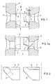
- 1 represents the piston which is guided in the pump piston liner 2 to move back and forth.
- the drive of the piston 1 is not shown.
- two diametrically opposite suction and overflow bores 3 are provided, with which the front edge 4 that determines the start of delivery and the oblique control grooves 5 that determine the end of delivery interact.
- the pump piston 1 assigns surface recesses 6, which have a depth a, on both sides in the areas interacting with the suction and overflow bores. These surface recesses are limited by edges 7.
- the depth a of the surface recess is indicated in the drawing for the sake of clarity and is in practice in a range between 0.02% and 0.2% of the pump piston diameter in order to ensure the desired throttling effect.
- a branched amount of fuel which is throttled in this surface recess 6, emerges from the working space 8 of the pump piston 1 into the suction and overflow bore 3 in the direction of arrow 9.
- vapor bubbles or cavities located in the suction and overflow bore 3 are flushed out of the suction and overflow bore 3 in the direction of the suction space.
- the suction and overflow bores 3 are opened by the oblique control edges 5, fuel jets entering the suction and overflow bores 3 under the high delivery pressure in the direction of arrow 10.
- the branched fuel jet emerging in the direction of arrow 9 deflects the fuel jet emerging at high pressure in the direction of arrow 10 from the wall of the suction and overflow bore 3.
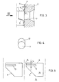
- FIGS. 3 and 4 show an embodiment in which a surface recess 12 is provided not on the piston skirt but on the piston running surface 11 of the pump piston liner 2. A small amount of fuel emerges from this surface recess 12 already at the start of delivery, as a result of which the same effect is achieved as in the arrangement according to FIGS. 1 and 2.
- the recess 12 extends in the circumferential direction only over the width of the, as shown in FIG Suction and overflow bore 3, so that a more precise throttling can take place in this surface recess 12.
- circumferential grooves 13 are provided on the piston skirt 14 below the end edge 4 of the piston and are connected to the working space 8 of the piston 16 via grooves 15.
- the width and depth of the grooves 13 determine the throttling.
- the grooves 13 are arranged at a distance b from the piston end edge 4 which determines the conveying end. This distance b is smaller than the diameter of the suction and overflow bores 3, so that the fuel enters the suction and overflow bores 3 already at the start of delivery and conveys the vapor bubbles away there.
Landscapes
- Engineering & Computer Science (AREA)
- Chemical & Material Sciences (AREA)
- Combustion & Propulsion (AREA)
- Mechanical Engineering (AREA)
- General Engineering & Computer Science (AREA)
- Fuel-Injection Apparatus (AREA)
Applications Claiming Priority (2)
| Application Number | Priority Date | Filing Date | Title |
|---|---|---|---|
| AT312086 | 1986-11-21 | ||
| AT3120/86 | 1986-11-21 |
Publications (1)
| Publication Number | Publication Date |
|---|---|
| EP0269610A1 true EP0269610A1 (fr) | 1988-06-01 |
Family
ID=3545614
Family Applications (1)
| Application Number | Title | Priority Date | Filing Date |
|---|---|---|---|
| EP87890265A Withdrawn EP0269610A1 (fr) | 1986-11-21 | 1987-11-20 | Elément de pompe d'une pompe à injection de combustible pour moteur à injection |
Country Status (1)
| Country | Link |
|---|---|
| EP (1) | EP0269610A1 (fr) |
Cited By (7)
| Publication number | Priority date | Publication date | Assignee | Title |
|---|---|---|---|---|
| DE3902764A1 (de) * | 1989-01-31 | 1990-08-02 | Bosch Gmbh Robert | Kraftstoffeinspritzpumpe |
| US4957418A (en) * | 1988-06-18 | 1990-09-18 | Robert Bosch Gmbh | Injection pump for internal combustion engines |
| GB2235955A (en) * | 1989-07-14 | 1991-03-20 | Daimler Benz Ag | Sloping-edge-controlled fuel injection pump for internal combustion engines |
| DE4006899A1 (de) * | 1990-03-06 | 1991-09-12 | Mak Maschinenbau Krupp | Verfahren und vorrichtung zur vermeidung einer kavitation an einem pumpenelement einer einspritzpumpe |
| DE4008902A1 (de) * | 1990-03-20 | 1991-09-26 | Kloeckner Humboldt Deutz Ag | Kraftstoffeinspritzpumpe |
| DE4127032A1 (de) * | 1991-08-16 | 1993-02-18 | Bosch Gmbh Robert | Kraftstoffeinspritzpume fuer brennkraftmaschinen |
| US5286178A (en) * | 1992-03-05 | 1994-02-15 | Robert Bosch Gmbh | Fuel injection pump for internal combustion engines |
Citations (6)
| Publication number | Priority date | Publication date | Assignee | Title |
|---|---|---|---|---|
| FR788268A (fr) * | 1935-03-08 | 1935-10-07 | Bosch Robert | Pompe d'injection pour moteurs diesel |
| FR1054678A (fr) * | 1952-01-21 | 1954-02-12 | Caterpillar Tractor Co | Pompe à injection perfectionnée |
| AT311727B (de) * | 1971-11-04 | 1973-11-26 | List Hans | Einspritzpumpe für Dieselmotoren |
| FR2200446A1 (fr) * | 1972-09-20 | 1974-04-19 | Maschf Augsburg Nuernberg Ag | |
| GB2133478A (en) * | 1983-01-08 | 1984-07-25 | Lucas Ind Plc | Fuel injection pumps |
| GB2135395A (en) * | 1983-02-14 | 1984-08-30 | Steyr Daimler Puch Ag | Fuel-injection unit for each cylinder of a diesel engine |
-
1987
- 1987-11-20 EP EP87890265A patent/EP0269610A1/fr not_active Withdrawn
Patent Citations (6)
| Publication number | Priority date | Publication date | Assignee | Title |
|---|---|---|---|---|
| FR788268A (fr) * | 1935-03-08 | 1935-10-07 | Bosch Robert | Pompe d'injection pour moteurs diesel |
| FR1054678A (fr) * | 1952-01-21 | 1954-02-12 | Caterpillar Tractor Co | Pompe à injection perfectionnée |
| AT311727B (de) * | 1971-11-04 | 1973-11-26 | List Hans | Einspritzpumpe für Dieselmotoren |
| FR2200446A1 (fr) * | 1972-09-20 | 1974-04-19 | Maschf Augsburg Nuernberg Ag | |
| GB2133478A (en) * | 1983-01-08 | 1984-07-25 | Lucas Ind Plc | Fuel injection pumps |
| GB2135395A (en) * | 1983-02-14 | 1984-08-30 | Steyr Daimler Puch Ag | Fuel-injection unit for each cylinder of a diesel engine |
Cited By (10)
| Publication number | Priority date | Publication date | Assignee | Title |
|---|---|---|---|---|
| US4957418A (en) * | 1988-06-18 | 1990-09-18 | Robert Bosch Gmbh | Injection pump for internal combustion engines |
| DE3902764A1 (de) * | 1989-01-31 | 1990-08-02 | Bosch Gmbh Robert | Kraftstoffeinspritzpumpe |
| DE3902764C2 (de) * | 1989-01-31 | 2002-10-17 | Bosch Gmbh Robert | Kraftstoffeinspritzpumpe |
| GB2235955A (en) * | 1989-07-14 | 1991-03-20 | Daimler Benz Ag | Sloping-edge-controlled fuel injection pump for internal combustion engines |
| GB2235955B (en) * | 1989-07-14 | 1993-08-04 | Daimler Benz Ag | Sloping-edge-controlled fuel injection pump for internal combustion engines |
| DE4006899A1 (de) * | 1990-03-06 | 1991-09-12 | Mak Maschinenbau Krupp | Verfahren und vorrichtung zur vermeidung einer kavitation an einem pumpenelement einer einspritzpumpe |
| DE4008902A1 (de) * | 1990-03-20 | 1991-09-26 | Kloeckner Humboldt Deutz Ag | Kraftstoffeinspritzpumpe |
| DE4127032A1 (de) * | 1991-08-16 | 1993-02-18 | Bosch Gmbh Robert | Kraftstoffeinspritzpume fuer brennkraftmaschinen |
| DE4127032C2 (de) * | 1991-08-16 | 1999-06-02 | Bosch Gmbh Robert | Kraftstoffeinspritzpume für Brennkraftmaschinen |
| US5286178A (en) * | 1992-03-05 | 1994-02-15 | Robert Bosch Gmbh | Fuel injection pump for internal combustion engines |
Similar Documents
| Publication | Publication Date | Title |
|---|---|---|
| EP0301310B1 (fr) | Machine à piston axiaux du type à plateaux ou axes inclinés avec des lumières de distribution et des canaux de compensation de pression | |
| EP0461212A1 (fr) | Pompe d'injection de carburant a commande electrique pour moteurs a combustion interne, en particulier pompe d'injection combinee avec l'injecteur. | |
| DE69303388T2 (de) | Anlage zur Energieumwandlung eines Fluidums mit veränderlicher Verdrängung | |
| CH679415A5 (fr) | ||
| DE3804843A1 (de) | Kraftstoffeinspritzpumpe fuer brennkraftmaschinen | |
| DE3809700C2 (fr) | ||
| DE69818382T2 (de) | Injektor | |
| EP0269610A1 (fr) | Elément de pompe d'une pompe à injection de combustible pour moteur à injection | |
| EP0263304B1 (fr) | Pompe d'injection de carburant pour moteurs à combustion interne | |
| EP0263807B1 (fr) | Partie de pompe à combustible pour moteur à injection | |
| EP0270519B1 (fr) | Elément de pompe d'une pompe à injection de combustible pour moteur à injection | |
| DE2532205C3 (de) | Brennstoffeinspritzpumpe für Dieselbrennkraftmaschinen | |
| EP0372211B1 (fr) | Pompe à injection de combustible pour moteur à combustion interne à injection | |
| EP0971123B1 (fr) | Pompe d'injection de carburant | |
| DE3644150C2 (de) | Kraftstoffeinspritzpumpe für Brennkraftmaschinen | |
| DE3734926C2 (fr) | ||
| EP0263808B1 (fr) | Partie d'une pompe à combustible pour moteur à injection | |
| DE3928375C2 (de) | Kolbenpumpe | |
| EP0153919B1 (fr) | Pompe d'injection de carburant pour moteurs à combustion interne | |
| EP0444256B1 (fr) | Dispositif d'injection de combustible pour moteurs à combustion interne à injection | |
| DE1208554B (de) | Pumpenelement fuer Einspritzpumpen | |
| EP0370263B1 (fr) | Ensemble de piston-cyclindre d'une pompe d'injection de combustible pour moteurs à combustion interne | |
| DE4006899A1 (de) | Verfahren und vorrichtung zur vermeidung einer kavitation an einem pumpenelement einer einspritzpumpe | |
| WO1991015675A1 (fr) | Dispositif d'injection de carburant pour moteurs a combustion interne a injection | |
| DE2003958C3 (de) | Kraftstoffeinspritzpumpe für Brennkraftmaschinen |
Legal Events
| Date | Code | Title | Description |
|---|---|---|---|
| PUAI | Public reference made under article 153(3) epc to a published international application that has entered the european phase |
Free format text: ORIGINAL CODE: 0009012 |
|
| AK | Designated contracting states |
Kind code of ref document: A1 Designated state(s): AT DE FR GB |
|
| STAA | Information on the status of an ep patent application or granted ep patent |
Free format text: STATUS: THE APPLICATION IS DEEMED TO BE WITHDRAWN |
|
| 18D | Application deemed to be withdrawn |
Effective date: 19890302 |
|
| RIN1 | Information on inventor provided before grant (corrected) |
Inventor name: STIPEK, THEODOR, DIPL.-ING. DR. |