EP0269620B1 - Bohrlochvorrichtung mit einer beschleunigerneutronenquelle - Google Patents
Bohrlochvorrichtung mit einer beschleunigerneutronenquelle Download PDFInfo
- Publication number
- EP0269620B1 EP0269620B1 EP86904502A EP86904502A EP0269620B1 EP 0269620 B1 EP0269620 B1 EP 0269620B1 EP 86904502 A EP86904502 A EP 86904502A EP 86904502 A EP86904502 A EP 86904502A EP 0269620 B1 EP0269620 B1 EP 0269620B1
- Authority
- EP
- European Patent Office
- Prior art keywords
- neutron
- detector
- source
- neutrons
- well logging
- Prior art date
- Legal status (The legal status is an assumption and is not a legal conclusion. Google has not performed a legal analysis and makes no representation as to the accuracy of the status listed.)
- Expired
Links
Images




Classifications
-
- G—PHYSICS
- G01—MEASURING; TESTING
- G01V—GEOPHYSICS; GRAVITATIONAL MEASUREMENTS; DETECTING MASSES OR OBJECTS; TAGS
- G01V5/00—Prospecting or detecting by the use of ionising radiation, e.g. of natural or induced radioactivity
- G01V5/04—Prospecting or detecting by the use of ionising radiation, e.g. of natural or induced radioactivity specially adapted for well-logging
- G01V5/08—Prospecting or detecting by the use of ionising radiation, e.g. of natural or induced radioactivity specially adapted for well-logging using primary nuclear radiation sources or X-rays
- G01V5/10—Prospecting or detecting by the use of ionising radiation, e.g. of natural or induced radioactivity specially adapted for well-logging using primary nuclear radiation sources or X-rays using neutron sources
- G01V5/101—Prospecting or detecting by the use of ionising radiation, e.g. of natural or induced radioactivity specially adapted for well-logging using primary nuclear radiation sources or X-rays using neutron sources and detecting the secondary Y-rays produced in the surrounding layers of the bore hole
-
- G—PHYSICS
- G01—MEASURING; TESTING
- G01V—GEOPHYSICS; GRAVITATIONAL MEASUREMENTS; DETECTING MASSES OR OBJECTS; TAGS
- G01V5/00—Prospecting or detecting by the use of ionising radiation, e.g. of natural or induced radioactivity
- G01V5/04—Prospecting or detecting by the use of ionising radiation, e.g. of natural or induced radioactivity specially adapted for well-logging
- G01V5/08—Prospecting or detecting by the use of ionising radiation, e.g. of natural or induced radioactivity specially adapted for well-logging using primary nuclear radiation sources or X-rays
- G01V5/10—Prospecting or detecting by the use of ionising radiation, e.g. of natural or induced radioactivity specially adapted for well-logging using primary nuclear radiation sources or X-rays using neutron sources
-
- G—PHYSICS
- G01—MEASURING; TESTING
- G01V—GEOPHYSICS; GRAVITATIONAL MEASUREMENTS; DETECTING MASSES OR OBJECTS; TAGS
- G01V5/00—Prospecting or detecting by the use of ionising radiation, e.g. of natural or induced radioactivity
- G01V5/04—Prospecting or detecting by the use of ionising radiation, e.g. of natural or induced radioactivity specially adapted for well-logging
- G01V5/08—Prospecting or detecting by the use of ionising radiation, e.g. of natural or induced radioactivity specially adapted for well-logging using primary nuclear radiation sources or X-rays
- G01V5/10—Prospecting or detecting by the use of ionising radiation, e.g. of natural or induced radioactivity specially adapted for well-logging using primary nuclear radiation sources or X-rays using neutron sources
- G01V5/104—Prospecting or detecting by the use of ionising radiation, e.g. of natural or induced radioactivity specially adapted for well-logging using primary nuclear radiation sources or X-rays using neutron sources and detecting secondary Y-rays as well as reflected or back-scattered neutrons
-
- G—PHYSICS
- G01—MEASURING; TESTING
- G01V—GEOPHYSICS; GRAVITATIONAL MEASUREMENTS; DETECTING MASSES OR OBJECTS; TAGS
- G01V5/00—Prospecting or detecting by the use of ionising radiation, e.g. of natural or induced radioactivity
- G01V5/04—Prospecting or detecting by the use of ionising radiation, e.g. of natural or induced radioactivity specially adapted for well-logging
- G01V5/08—Prospecting or detecting by the use of ionising radiation, e.g. of natural or induced radioactivity specially adapted for well-logging using primary nuclear radiation sources or X-rays
- G01V5/10—Prospecting or detecting by the use of ionising radiation, e.g. of natural or induced radioactivity specially adapted for well-logging using primary nuclear radiation sources or X-rays using neutron sources
- G01V5/107—Prospecting or detecting by the use of ionising radiation, e.g. of natural or induced radioactivity specially adapted for well-logging using primary nuclear radiation sources or X-rays using neutron sources and detecting reflected or back-scattered neutrons
Definitions
- the invention relates to a well logging tool for investigating an earth formation surrounding a borehole and determining the characteristics of the earth formation as e.g. described in US-A-3823319. More particularly, the invention permits a more accurate determination of formation porosity and other characteristics, such as the macroscopic capture cross section, by using an accelerator neutron source. It also relates to improved apparatus for monitoring the output of an accelerator neutron source.
- Knowledge of the porosity of an earth formation surrounding a borehole is important in the petroleum industry to identify possible oil and gas producing regions and to calculate the maximum producible oil index of a formation, as well as other important parameters.
- known well logging tools for measuring porosity use a chemical neutron source, e.g., Cf252, AmBe, or PuBe, and two or more neutron detectors spaced at different distances from the source. Tools of this type are described in detail in U.S. patent number 3,483,376 issued to S. Locke on December 9, 1969, and U.S. patent number 3,566,117 issued to M. Tixier on February 23, 1971.
- Chemical neutron sources are subject to problems of handling, shipment and storage which seriously hinder their use. Indeed, because of the concern about radiation safety, regulations applying to chemical sources are becoming more restrictive and may, in the future, prohibit their use altogether. Furthermore, chemical sources have limitations with respect to output intensity, typically being on the order of 4 x 10⁷ neutrons per second or less. The use of larger chemical sources, even if possible within the constraints of well tool design, would merely exacerbate the aforementioned radiation safety problems.
- accelerator neutron sources are also available for possible use in well logging tools, e.g. an accelerator based on the deuterium-tritium (D-T) reaction that produces 14-MeV neutrons, an accelerator based on the deuterium-deuterium (D-D) reaction that produces 2.5-MeV neutrons, and an accelerator based on the tritium-tritium (T-T) reaction that produces a spectrum of 1- to 10-MeV neutrons, with the average energy of the neutrons near 5 MeV.
- D-T deuterium-tritium
- T-T tritium-tritium
- An example of a D-T accelerator neutron source is shown in U.S. patent number 3,775,216, issued to A. Frentrop on November 27, 1973, and assigned to the assignee of this application.
- accelerator neutron source may be switched on and off as desired, the radiation problems arising from the use of a chemical source do not exist with accelerator sources.
- a further advantage of accelerator sources is the increased neutron source strength possible.
- neutron outputs of 5 x 10⁸ neutrons per second or greater are readily available, which is an order of magnitude greater than of chemical sources.
- accelerator sources also afford increased statistical accuracy and permit logging operations to be performed more rapidly.
- the higher source strength increases design flexibility regarding shielding and spacing between different detectors and spacing between a particular detector and the source, so that the performance of the sonde may be improved. For example, larger detector spacings lead to smaller borehole effects.
- Various devices for monitoring the output of neutron generators have been suggested.
- such devices include means for distinguishing source neutrons, i.e., neutrons emitted directly by the source that have not interacted with any nuclei, from other radiation, e.g., lower-energy, scattered neutrons and naturally occuring and induced gamma rays.
- source neutrons i.e., neutrons emitted directly by the source that have not interacted with any nuclei
- An example of such a neutron source intensity monitor is disclosed in U.S. patent number 4,268,749 to Mills.
- a fast neutron detector preferably of the helium-3 type with high helium-3 gas pressure, is used to detect neutrons, and signals from the detector are transmitted to a discriminator that is biased to count helium-3 recoils from source neutrons and discriminate against nonsource neutrons from the formation.
- U.S. patent number 4,271,361 to Jacobs Another example of a neutron source intensity monitor is disclosed in U.S. patent number 4,271,361 to Jacobs.
- an arsenic layer is employed to emit gamma rays of approximately 17 milliseconds half life when excited by incident fast neutrons.
- a gamma ray detector adjacent to the arsenic layer detects the gamma rays and applies signals representative thereof to an energy-selective counting circuit, which counts the arsenic-originating gamma ray events as an indication of source intensity.
- Still another example of a neutron source intensity monitor is a device having a scintillator, a photomultiplier, and a pulse shape discriminator for distinguishing source neutrons from other radiation.
- the prior devices tend not to be borehole compatible, i.e., they are affected by scattered-back neutrons, naturally occurring radiation, and other borehole effects resulting from the borehole contents, size, formation matrix, and the like.
- the high temperatures and other harsh conditions typically encountered in a borehole often necessitate complex gain compensation circuitry or other measures, such as cryogenic flasks, to stabilize the monitor.
- pulse shape discriminators in addition to having very complex electronics, work well only with liquid scintillators, which makes high-temperature operations difficult, and are comparatively slow, which prevents their use in applications where counting rates are high.
- the monitor preferably comprises an organic scintillator having a characteristic dimension that is small relative to the average range of gamma ray-induced (Compton scattering) electrons that would produce light pulses of magnitudes comparable to those resulting from recoil protons produced by source neutrons, while it is large relative to the average range of such recoil protons.
- the scintillator is coupled via a photomultiplier to a pulse height discriminator circuit that passes pulses in the higher-energy portion of the flat portion of the scintillator pulse height spectrum where the spectrum is dominated by source neutrons. Consequently, the neutron source monitor produces a signal that is proportional to the output strength, or intensity, of the neutron source.
- the source monitor has good inherent gain stability, but if needed active gain compensation can be provided through, for example, the use of another pulse height differential discriminator to pass a second range of pulses and by comparing a ratio of the count rates from the two pulse ranges to a reference value.
- the source monitor may be used to measure the decay of the thermal neutron population in the earth formation surrounding the borehole for purposes of deriving formaton sigma. To that end, capture gamma rays detected by the monitor during periods between neutron bursts are detected and sorted in a timing multiscaler.
- the near epithermal neutron detector is placed close to the neutron source.
- the shield for the near epithermal detector raises its low energy neutron detection threshold to approximately 10 eV to 100 eV, while maintaining sensitivity to higher neutron energies, and suitably comprises an annulus of neutron moderating-neutron absorbing materials surrounding the near detector. This arrangement affords increased ratio porosity sensitivity over the entire range (0%-40%) of interest.
- No high density shielding is located between the neutron source and the near epithermal neutron detector, which permits very close spacing of the near detector to the source. Such close source-detector spacing contributes to enhanced ratio porosity sensitivity.
- the novel shielded near-spaced neutron detector structure may be employed independently as a monitor of high energy neutron flux. In this mode of operation, it is particularly useful to monitor the source strength of D,T-type neutron accelerators.
- the far epithermal detector is positioned with respect to the neutron source so that the detector remains fully sensitive to the formation porosity, and preferably is eccentered in the sonde and rearshielded to further enhance its sensitivity to the formation and decrease its sensitivity to borehole neutrons.
- the porosity of the formation can be determined by taking a ratio of the output signal from the near epithermal detector to the output signal from the far epithermal detector, i.e., by the ratio technique, or by using a plot of the signal from the near epithermal detector normalized by the signal from the neutron source monitor versus the signal from the far epithermal neutron detector normalized by the signal from the neutron source monitor, i.e., by the crossplot technique. With either technique, a porosity determination comparable to or better than that afforded by prior art chemical source tools is obtained, while at the same time avoiding the safety and intensity limitations associated with the prior art tools.
- the intermediately-spaced neutron detector array preferably includes a pair of axially-spaced neutron detectors of like energy sensitivity (epithermal or thermal) to provide greater spatial resolution in the porosity measurement. This is particularly useful for thin bed definition.
- the detector pair is preferably eccentered in the sonde and back-shielded to reduce borehole effects.
- a third neutron detector in the array may have a substantially different neutron energy sensitivity, i.e., thermal if the axially-spaced pair is epithermal sensitive and epithermal if the pair is thermal sensitive, and is preferably located at the same source-detector spacing as the more closely spaced of the detector pair of the array.
- the third detector is preferably transversely offset from the detector pair and backshielded to reduce borehole effects.
- the epithermal/thermal count rate ratio of the two like-spaced detectors can be used to provide a local, derived formation sigma and for comparison of the epithermal and thermal neutron fluxes.
- the optional far thermal detector is located farther from the neutron source than the far epithermal neutron detector, but close to it to enhance the statistical accuracy of the measurements.
- the thermal neutron detector is preferably eccentered in the sonde and shielded on the side facing the borehole so that borehole environmental effects are reduced. The provision of a thermal neutron detector in the tool permits determination of formation characteristics dependent upon thermal absorption, such as the formation capture cross section ⁇ , but also has good porosity sensitivity and statistical precision.
- the accelerator neutron source is a D-T source, although other types of accelerators may be used if desired.
- Suitable neutron detectors are helium-three (He-3) proportional counters, with the two detectors closest to the neutron source, i.e., the near epithermal neutron detector and the far epithermal neutron detector, being covered by a thin cadmium layer in order to render the detectors insensitive to neutrons with energies below approximately 0.5 eV.
- FIG. 1 Illustrative embodiments of an apparatus based on the principles of the invention are shown in the figures, in which like reference numerals designate like components.
- a well logging tool, or sonde, 10 for investigating the porosity, thermal neutron capture cross section and other parameters of an earth formation surrounding a borehole is shown.
- the sonde 10 includes an accelerator neutron source 12, a neutron source monitor 14, a near epithermal neutron detector 16, a thermal/epithermal neutron detector array 17, a far epithermal neutron detector 18, and a thermal neutron detector 20.
- Shields 22, 24, and 26 are provided to shield the detectors 16, 18, and 20, respectively.
- a shield 28 is located between the near epithermal neutron detector 16 and the far epithermal neutron detector 18 and also serves to shield the thermal/epithermal detector array 17.
- the tool 10 is intended to be a sidewall tool, and a bow spring, indicated schematically at 11, or other conventional device may be provided on the tool to urge it against the borehole wall.
- a bow spring indicated schematically at 11, or other conventional device may be provided on the tool to urge it against the borehole wall.
- the tool is primarily intended for open hole logging, it may be used in cased holes and, if desired, may be sized for through-tubing use.
- the neutron accelerator 12 may be of any suitable type, but preferably is a D-T type (14 MeV) source having an output on the order of 5 x 10⁸ n/sec or greater for enhanced detector statistics and logging speed.
- the accelerator package includes the necessary high-voltage power supply and firing circuits incident to accelerator operation, and these circuits may also be conventional.
- the accelerator may be operated in either the continuous (d.c.) mode or the pulsed mode. If the latter mode is used, the accelerator package would of course also include the necessary pulsing circuits, as is known.
- suitable power supplies (not shown) are likewise provided in the tool 10 to drive the detectors 16, 17, 18 and 20 and other downhole electronics.
- the monitor 14 is located closely adjacent to, or on, the radius of the accelerator neutron source 12, with the scintillator 30 at the position of the target 34 of the accelerator 12.
- the monitor may have to be located coaxially with the source; for instance, in some cased-hole tools.
- the scintillator 30 may be spaced as far as 30 cm from the source 12, as is described more fully hereinbelow.
- the neutron source monitor 14 With the neutron source monitor 14 appropriately sized and located, it is responsive during and immediately following the burst primarily to unmoderated neutrons that are incident on it directly from the neutron source, thereby reliably detecting changes in the output intensity of the source 12, and is relatively unaffected during such period by changes in borehole or formation characteristics. Consequently, the output signal of the neutron source monitor 14 is useful, as described hereinafter, in normalizing the output signals of the epithermal and thermal neutron detectors for source strength fluctuation.
- the monitor 14 has good inherent gain stability, but, as illustrated schematically herein in Figures 5 and 13, where still greater gain stability is need, it can be used in a circuit for feedback control of the photomultiplier high-voltage power supply for the monitor.
- the monitor 14 may also be used to detect capture gamma rays as a function of time after the burst for the purpose of determining the formation sigma.
- the data detection and processing steps for obtaining formation sigma are described in more detail in connection with Figure 5.
- the near epithermal neutron detector 16 and the far epithermal neutron detector 18 shown in Figure 1 are preferably helium-three (He-3) proportional counters covered by a thin, e.g., 0.020 inch (0.05 cm), cadmium shield to make the detectors insensitive to neutrons having energies below the epithermal range, i.e., below about 0.5 eV.
- Other types of neutron detectors such as boron triflouride (BF3) detectors, may of course be used.
- Detectors 16 and 18 provide the primary porosity measurement.
- the sensitive, or active, volume of the near detector 16 should be located in close proximity to the source 12, without intervening high density shielding.
- a suitable spacing would be on the order of 8 to 10 inches (20 cm to 25 cm) between the center of the sensitive volume to the target of a D-T accelerator.
- Such close source-detector spacing enhances the ratio porosity sensitivity as compared to a longer-spaced detector with intervening shielding.
- the optimum source-detector spacing will vary with a number of factors, e.g. detector size, pressure, source intensity, accelerator type, and the like.
- the shield 22 for the near detector 16 is annular in shape and encircles the sensitive volume of the near detector and, as described more fully hereinbelow, is designed to raise the low energy neutron detection threshold of the near detector to a level at which the detector efficiency is nominally maximum for higher energy ranges. To that end, the detector threshold is raised to at least approximately 10 eV and preferably to on the order of 100 eV. With the shield 22 designed thusly and a near detector located in close proximity to the source without intervening high density shielding, the near detector is relatively insensitive to changes in the porosity of the formation since neutrons that have interacted with the formation will generally have energies below the low energy neutron detection threshold of the detector.
- the near detector will remain sensitive to borehole environmental and tool standoff effects since neutrons that have interacted only with the contents of the borehole will generally have energies above 10 eV. Consequently, the output signal from the near detector may be used to compensate other detector signals for borehole environmental and tool standoff effects.
- Apparatus and techniques useful for that purpose are described in the commonly-owned U.S. Patents No. 4,423,323 issued December 27, 1983 to Ellis et al. and No. 4,524,274 issued June 18, 1985 to Scott. Further details regarding the configuration and spacing and function of the near detector 16 and the construction of the shield 22 are described hereinbelow in connection with Figures 8-12.
- the spacing of the far detector 18 from the source 12 is preferably selected to maximize statistical precision, i.e., counting sensitivity, while minimizing the effects of such environmental factors as tool standoff and the like. Generally, the standoff effect is reduced at greater spacings, but only at the cost of reduced counting rates.
- a suitable spacing from the accelerator target 34 to the center of the sensitive volume of the far detector 18, shielded as described hereinafter would be on the order of 23-27 inches (58 cm-68 cm). As with the near detector, the optimum spacing will vary depending upon the size of the active volume, the pressure of the detector, etc.
- the far epithermal detector 18 is eccentered to one side of the sonde 10 and oriented towards the formation by shielding.
- the shield 24 for the far epithermal detector is cylindrical in shape with a slot 36 therein, with the far detector 18 being located in the slot.
- the shield 24 thereby shields the sensitive volume of the far detector from neutrons incident on it from the side of the sonde towards the borehole, i.e., the side of the sonde away from the formation.
- the effect of such eccentering and rear-shielding of the far detector is to decrease the sensitvity of the far detector to borehole environmental effects and thereby increase its sensitivity to changes in the porosity of the formation.
- the comparatively long spacing between the source 12 and the far detector 18 makes the far detector 18 relatively insensitive to source neutrons.
- an additional shield 28 may be provided between the near detector 16 and the far detector 18 to further reduce the sensitivity of the far detector to source neutrons.
- the shield 28 also surrounds and shields the thermal/epithermal detector array 17 located between the near and far epithermal detectors 16 and 18.
- the array 17 includes a plurality, e.g. three, relatively small He-3 detectors 17a, 17b and 17c.
- the detectors 17a and 17b are preferably aligned axially of the tool 10 in end-to-end relation. Where space limitations do not permit such axial alignment, the detectors 17a and 17b may be cicumferentially offset, but preferably so as to be symmetrically positioned on either side of the line of contact of the tool 10 with the borehole (or casing) wall. In either case, the detectors 17a and 17b provide measurements of the neutron flux at the two detector locations.
- the difference between the counting rates at the two detectors affords enhanced spatial resolution of porosity and other formation parameters. This is particularly useful for thin bed definition.
- the detectors 17a and 17b may be sensitive to either epithermal neutrons or thermal neutrons, to provide either an epithermal porosity measurement or a thermal porosity measurement. As shown in Figure 4, they are preferably located in an axial slot 31 in the shield 28 so as to enhance sensitivity to the formation and to reduce sensitivity to the borehole.
- the third detector 17c is preferably located at the same spacing from the source 12 as the detector 17a. It also is a He-3 neutron detector, but with a different energy sensitivity than the detectors 17a and 17b. Thus if the detectors 17a and 17b are epithermal detectors, the detector 17c should be a thermal detector, and vice versa.
- the epithermal/thermal flux ratio from the two like-spaced detectors 17a and 17c can be used to provide a local, derived formation sigma measurement and for comparison between epithermal and thermal porosity measurements.
- the epithermal/thermal count rate ratio can be expected to increase as formation sigma increases and to decrease as sigma decreases.
- the detector 17c is advantageously circumferentially and transversely offset from detector 17a, and may conveniently be located within the same slot 31 as the detectors 17a and 17b.
- He-3 detector array 17 The arrangement and configuration of the He-3 detector array 17 are shown in Figures 1 and 4 in an idealized, i.e., illustrative, manner, and other arrangements and configurations may of course be employed.
- the principal purposes of the array are to provide enhanced spatial resolution in the porosity measurement, a local sigma measurement, and an epithermal/thermal flux comparison.
- the particular detector sizes, pressures, and source spacings employed may be selected as desired to optimize detection performance.
- the neutron absorber is preferably a l/v type such as boron or the like, where v is neutron velocity.
- a suitable shielding material is boron carbide (B4C) distributed in an epoxy binder or some other hydrogenous binding medium, e.g. 65% B4C by weight in epoxy.
- B4C boron carbide
- the shields 22, 24, and 28 should each be thick enough to accomplish its intended purpose with the shielding material selected. For example, if the shield 22 is made from the aforementioned 65% B4C-epoxy material, a thickness of roughly 1 inch (2.5 cm) has been found satisfactory in order to raise the low energy neutron detection threshold of the near detector from 0.5 eV to approximately 10 eV and higher.
- the neutron source monitor 14 and the neutron detectors 16, 17, 18, and 20 appropriately spaced and shielded, improved determinations of formation porosity can be made. Since, as explained previously, the near detector 16 is relatively less sensitive to changes in porosity but relatively more sensitive to borehole environmental and tool standoff effects and the far detector 18 is relatively more sensitive to changes in porosity, an improved porosity determination can be made using either the ratio technique or, following normalization of the individual detector count rates by use of the neutron monitor intensity measurement, by a cross plot of the near detector 16 and far detector 18 count rates. As mentioned, the outputs of the array detectors 17a, 17b and 17c may be employed to obtain porosity measurements having enhanced vertical resolution, and also to provide a comparison between epithermal and thermal porosity measurements.
- the porosity response of the thermal neutron detector 20 is relatively less sensitive to borehole size and tool standoff effects than the porosity response of the epithermal detectors 16 and 18, its output may be used to derive an additional porosity measurement.
- Such a thermal neutron porosity measurement may be of particular value where the thermal detector response is free of significant influence by neutron absorbers in the formation and borehole environment.
- the thermal detector output allows the macroscopic capture cross section ⁇ and other formation capture characteristics to be determined in the same tool with the epithermal porosity measurement.
- the neutron monitor 14 is used to detect capture gamma rays following the neutron bursts
- the far-spaced thermal detector 20 may be omitted and the capture cross section and other thermal neutron-related parameters of the formation may be obtained from the monitor gamma ray data.
- the output signals from the He-3 epithermal detectors 16 and 18 may be amplified and counted in any suitable way to derive a count rate (N) for the near detector 16 and a count rate (F) for the far detector 18.
- N count rate
- F count rate
- the detector signals from the detectors 16 and 18 may be fed to charge sensitive preamplifiers 35 and 37 and thence to pulse amplifiers 38 and 40, with the spectrum of amplified pulses from each detector then being sent to a leading edge discriminator 42 and 44 whose output drives a scaler 46 and 48.
- the scaler outputs are applied to signal processing circuitry 50, which may comprise a suitably programmed digital computer, microprocessor or other data processing device, for generation of the ratio N/F of the near detector scaler counts (N) to the far detector scaler counts (F) as an indicator of porosity.
- This indicator has been found to be subject to relatively small environmental (mudcake, borehole size, etc.) effects and tool standoff effects, and thus to provide an accurate, reliable porosity measurement.
- the N/F ratio signal may be applied in conventional fashion to a recorder/plotter 52 for recording as a function of tool depth.
- Figure 6 shows the near/far (N/F) ratio response as measured in limestone formations of porosities of 0, 13.2, ,29.3 and 40.6 % with an 8-inch, uncased borehole.
- N/F near/far
- a porosity determination may also be made by means of a crossplot of the near and far detector count rates.
- the crossplot technique allows for correction for environmental effects.
- Figure 7 is a near-far (N-F) crossplot for 0 to 41% porosities in sandstone, limestone and dolomite formations, and illustrates the effect of matrix change on the crossplot.
- the data plotted are for an 8-inch, uncased borehole.
- the N and F count rates are first normalized by the output of the neutron flux monitor 14.
- the detector scaler 46 and 48 output signals are each divided into the count rate (intensity) output signal (Window A) from the monitor 14, as indicated in Figure 5 by the outputs A/N and A/F from the signal processing circuitry 50.
- the manner in which the intensity output signal A is generated by the monitor 14 and its associated circuitry (54-60 in Figure 5) is described hereinbelow in connection with Figures 13-15.
- the normalized far detector count rate F is also highly porosity sensitive and may be used if desired to derive porosity information. It is, however, somewhat more susceptible to environmental effects than the N/F ratio, but this susceptibility can be decreased by use of higher strength accelerators together with greater source-to-detector spacings.
- the far thermal detector output signals may likewise be similarly amplified, discriminated and scaled (components 62-68 in Figure 5) to provide a scaler output count rate T for the thermal detector 20.
- This signal is preferably normalized by the monitor output signal A, and may be used to derive a measurement of the formation macroscopic capture cross section ⁇ . It may also be used, either alone or in conjunction with one or more of the normalized epithermal detector count rate signals A/N and A/F, to derive porosity information or to evaluate the influence of neutron absorbers on the porosity measurement. Any or all of these functions may be readily implemented in the signal processing circuits 50 in any suitable manner.
- the output from each of the detectors in the array 17 is also suitably amplified, discriminated and scaled (components 70-76 in Figure 5), and the count rates therefrom Ar 1, Ar 2 and Ar 3, respectively, are transmitted to the surface signal processing circuits 50.
- the circuitry for the detectors 17a, 17b and 17c is shown collectively in Fig. 5, but it will be understood that each detector will have the appropriate individual components.
- the count rates Ar 1, Ar 2 and Ar 3 are recorded as a function of tool depth.
- the difference in count rates between detectors 17a and 17b (Ar 1-Ar 2) may also be formed and recorded vs. depth to provide the aforementioned enhanced spatial information for greater vertical resolution of the porosity measurement.
- count rates may first be normalized by reference to the output signal A from the monitor 14 to minimize the effect of source strength fluctuation on the individual count rates Ar 1 and Ar 2.
- the epithermal/thermal ratio e.g. Ar 1/Ar 3
- a local formation sigma may be derived and recorded, as indicated in Figure 5.
- a second channel 78 (see Fig. 5) is provided in the monitor output circuitry to couple the detector output pulses via a leading edge discriminator 80 to a timing multiscaler 82.
- the threshold level of the discriminator 80 is set at a relatively low level, e.g., in the range of 50 KeV (equivalent gamma ray energy), to enhance count rate statistics.
- the multiscaler 82 sorts the pulses into time bins and transmits the count per bin data G i , where i is the bin number, to the surface in digital format. Preferably a sufficient number of time bins, e.g.
- the count data G i are processed at the surface to derive formation sigma in any suitable manner.
- formation sigma may be determined in accordance with the technique disclosed in U. S. Patent No. 4,292,518 issued September 29, 1981 to C. W. Johnstone.
- a diffusion correction is preferably made to the sigma value determined therefrom.
- the capture gamma ray data G i are preferably both deadtime and background corrected. Background measurements are preferably made during periodically repeated intervals during which the neutron bursts are suppressed, in accordance with the techniques disclosed in U.S. Patent No. Re. 28,477 issued July 8, 1975 to W. B. Nelligan.
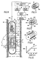
- the sonde 10 is shown as suspended in a borehole 84 by a cable 86 for investigating the porosity of a subterranean formation 88.
- the borehole is illustrated as an open hole and as containing a well fluid 89.
- the sonde 10 may be sized for through-tubing use, as aforementioned.
- the conventional hoist and depth-recording devices would also be employed, as will be evident to those skilled in the art.
- the sonde will also be understood to include a bow spring or other conventional device (see 11 in Figure 1) for urging the sonde against the borehole wall as shown.
- the sonde 10 includes a neutron accelerator 12, a near-spaced neutron detector 16 and a far-spaced neutron detector 18.
- the accelerator and detectors may be of the types described in connection with Figure 1
- the embodiment of Figure 8 is otherwise generally similar to that of Figure 1, except that the detector array 17 and the thermal detector 20 have been omitted.
- Electrical power for the sonde 10 is supplied over the cable 86 from a power supply (not shown) at the surface. It will be understood that suitable power supplies (not shown) are likewise provided in the sonde 10 to drive the detectors 16 and 18 and other downhole electronics.
- the detectors 16 and 18 may be conventional and preferably are of the He-3 gas-filled type.
- a suitable gas pressure for purposes of the invention is ten atmospheres for the near detector 16 and fifteen atmospheres for the far detector 18, but these may be varied as desired to optimize the energy response of the detector.
- the near-detector 16 is surrounded by a novel shielding structure to modify the energy response of the near-detector system as a whole (detector 16 plus shield structure) so as to render it predominantly sensitive to neutrons having energies greater than 10-100 eV and above incident thereon directly from the accelerator 12 or its immediate vicinity.
- this porosity determination is sensitive to formation porosity over the entire porosity range from 0 to 100 p.u. (porosity units) of interest in oil explorations, of which the range is typically from 0 to about 40 p.u. or higher.
- the near detector 16 is located close to the accelerator 12.
- a detector having an active (sensitive) volume of approximately 1 inch x 3 inch (2.5 cm x 7.6 cm) a centerline spacing from the target of the accelerator in the range of 6-10 inches (15-26 cm) has been found suitable.
- the far detector which is larger for better statistics, e.g. 1 inch x 6 inch (2.5 cm x 15 cm), is suitably spaced with its center within the range of 20-26 inches (50 cm-66 cm) from the accelerator target.
- Both detectors may be clad in cadmium to raise the detection system detection thresholds to epithermal or higher energy levels, or only one or neither may be so clad.
- the cadmium cladding 104 is illustrated in Figure 8 on the near detector only and is shown exaggerated in thickness for clarity. An approximate thickness is on the order of 0.05 cm. Where sensitivity to thermal neutrons is desired, either or both detectors may be unclad.
- the near detector 16 is additionally surrounded by an annular shield 106 composed of boron carbide (B4C) in an epoxy binder or some other hydrogenous binding medium.
- the shield 106 is annular in cross section and is formed with a central bore 108 for receipt of the cadmium-clad detector 16.
- the shield 106 thus performs a dual function, acting both as a neutron moderator, by virtue of the hydrogenous binder, and as a neutron absorber, by virtue of the boron carbide.
- suitable proportions for the shield may be approximately 47% by volume of B4C and 53% by volume of binder.
- the combined B4C-epoxy shield structure moderates the energies of those neutrons directly incident on the detector 16 from the source 12 to levels more readily detected by the He-3 detector 16, and second, it shifts the relative sensitivity of the near detector system towards higher energy neutrons and away from lower energy neutrons.
- the signal produced by detector 16 has a relatively smaller component indicative of the characteristics of the formation and a relatively larger component indicative of the initial neutron flux intensity from the source. This may be better understood by reference to the following description of a theoretical, somewhat simplified model of the principal neutron interactions which occur in the region of the sonde 10, as indicated diagrammatically by neutron paths a - e in Figure 8.
- the accelerator may be regarded for present purposes as an essentially isotropic neutron source, with neutrons emanating in all directions.
- the neutrons following paths a and b may be considered representative of those which travel through the sonde 10, the well fluid 89, and enter the formation 88, undergoing scattering reactions along their path lengths, and which are then scattered back to the sonde in the region of the near detector system.
- Such neutrons are hereinafter referred to as "far field" (formation) neutrons. Due to the energy loss resulting from the scattering reactions, the far field neutrons are statistically less likely to successfully traverse the B4C-epoxy shield 106 and are more likely to be absorbed therein.
- Neutrons scattered back from the borehole contents are more likely to have higher energy than those illustrated by paths a and b and therefore might traverse the outer B4C-epoxy shield 106. These neutrons are likely to be so moderated in energy in the process as to have a high probability of being absorbed in the cadmium cladding 104. This is illustrated by the path c in Fig. 1. These neutrons are referred to hereinafter as "near field" neutrons.
- neutrons impinging directly on the outer shield 106 such as those represented by path d , as well as other neutrons having undergone relatively less energy loss through either few major scatterings or many slight scatterings, are statistically most likely to pass through both shields 106 and 104 and reach the sensitive volume of the detector. At least some, however, will be sufficiently moderated in energy by the B4C-epoxy shield to be within the sensitive range of the He-3 detector 16. These neutrons are referred to hereinafter as "source" neutrons.
- the combined effect of the shields 106 and 104 is to render the near detector 16 largely responsive to neutrons which carry little information from the formation and borehole environment. Since the scattering and absorption processes involved are statistical in nature, there will of course be some overlap between the categories of neutrons in this model that are detected, i.e., most, but not all, far field neutrons reaching the near detector will be stopped by the shielding and not counted. So the near detector will retain a slight porosity sensitivity. A larger, but still not predominant, proportion of the total neutrons counted will be near field neutrons, and the remaining predominant category of the neutrons counted will be source neutrons.
- the cadmium cladding raises the detection threshold of the detectors to epithermal energy or higher, e.g. to 0.5 ev and above.
- the thickness of the B4C-epoxy shield 106 can be selected to provide the desired threshold level for the detector. Generally, the level should be selected at or about the point where the detector is at the maximum nominal efficiency for detection of the higher energy source neutrons, i.e., at about the energy level at which the source neutrons will begin to be filtered out, e.g., at least approximately 10 eV and preferably on the order of 100 eV.
- the outer shield 106 is shown as composed of two annuli, the outer one 110 of a hydrogenous material such as polyethylene and the inner one 112 of B4C.
- the shielding materials may also be arranged in other ways.
- the absorber material e.g.
- B4C is shown arranged in circumferentially-spaced sectors 114A, 114B, 114C and 114D interleaved by alternate sectors 116A, 116B, 116C and 116D of moderator material, e.g., epoxy resin.
- moderator material e.g., epoxy resin.
- This particular construction is useful in reducing the sensitivity of the detector-shield system to the spatial distribution of neutron energies.
- the energy response of the detector system could also be altered by removing the cadmium cladding or by using another material having a different energy absorption cross section for the cladding, such as indium, gadolinium or silver.
- the embodiment of Figure 11 wherein the moderating material or materials are arranged in layers 118A, 118B, etc., between alternate axially-spaced layers 120A, 120B, etc. of absorbing material or materials, is useful for applications where it is desired to take advantage of or compensate for the axial distribution of neutrons along the length of the detector.
- the same moderating material and absorbing material may be used throughout, or, as indicated in Figure 11, different types of moderating materials M1, M2, etc., and different types of absorbing materials A1, A2, etc., may be employed.
- Figure 12 illustrates the comparative porosity sensitivity of the embodiment of Figure 8 relative to the prior art 14 Mev two-detector porosity technique.
- the solid-line graph 122 represents the plot of the N/F ratio as a function of porosity in the prior art tool. As previously mentioned, this graph shows little, if any, porosity response above about 20 p.u.
- the porosity response of the N/F ratio formed using the shielded-detector technique of the present invention represented by the dotted-line graph 124, shows significant change with porosity over the full range up to and above 40 p.u.
- B4C as an element of the detector shielding
- B10 has the greater absorption cross section, but a lower material concentration.
- a possible shielding composition might be B4C enriched in B10.
- other high-cross section l/v-like absorbers could be used, such as lithium carbonate in an epoxy resin binder.
- the Li2CO3 could advantageously be enriched in Li6.
- binder materials other than epoxy resin or hydrogenous materials other than polyethylene may be used as moderators in accordance with the invention.
- the neutron source intensity monitor 14 of the invention is shown in use in a more generalized borehole logging tool 10.
- the disposition of the tool within the borehole 84 is essentially the same as in Figure 8, except that the sonde is not eccentered and a mudcake 126 is shown as formed on the borehole wall.
- the sonde 10 is depicted as containing a neutron source 12, the monitor 14, a near-spaced detector 16, and a far-spaced detector 18.
- the two detectors shown are intended to be illustrative of a typical detector arrangement in a sonde, and the sonde might contain only one or several such detectors. The detectors themselves may be of any suitable type.
- the sonde might also contain shielding, as shown in Figures 1 and 8 for example, for the neutron source and/or for the detectors.
- the scintillator may be located in a dewar flask or may be otherwise thermally insulated. It is an advantage of the invention, however, that such thermal insulation may be omitted by use of an appropriate hightemperature plastic scintillator.
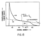
- count rate is plotted on the vertical axis and pulse height (recoil proton energy for curve 146 and Compton electron energy for curve 148) is plotted on the horizontal axis.
- the curve designated by reference numeral 146 is a curve of an observed scintillator pulse height spectrum for neutron-induced recoil proton events in a neutron-gated 3/4 inch x 3/4 inch (1.9 cm x 1.9 cm) NE-213 liquid scintillator.
- the source was a 14 MeV D-T accelerator.
- the curve designated by reference numeral 148 is a curve of an observed scintillator pulse height spectrum for gamma ray-induced Compton electron events inthe same scintillator, but gated for gammas.
- the total scintillator pulse height spectrum is obtained by adding the curves 146 and 148.
- the curves 146 and 148 were obtained by placing the scintillator about 1.8 inches (4.6 cm) from the target of a D-T accelerator neutron source.
- a pulse shape discriminator was used in order to separate the neutron induced events from the gamma ray-induced events.
- the curves of Figure 14 may be taken as representative of plastic scintillator spectra as well.
- the curve 146 is essentially a pulse height spectrum for recoil protons, with the corresponding recoil proton energy shown along the horizontal axis.
- neutron-proton scattering is basically isotropic in the center-of-mass system at the energies involved in Figure 14, the undistorted recoil proton pulse height spectrum is rectangular in shape.
- the observed pulse height spectrum is nonrectangular due to the influence of several factors, including multiple neutron scattering, escape of recoil protons from the scintillator volume, nonlinear light response of the scintillator-photomultiplier, and the resolution function of the equipment.
- the curve 146 has essentially two portions: a first portion that remains substantially flat or decreases slightly at higher energies, i.e., energies from the discriminator threshold level at about 3-4 MeV up to 12-13 MeV, as energy increases, and a second portion that decreases rather rapidly at still higher energies, i.e., energies above 13-14 MeV, as energy increases.
- the neutron-induced spectrum 146 is much higher, usually by at least two orders of magnitude, than the gamma ray-induced spectrum 148. Therefore, the total scintillator pulse height spectrum, which is obtained by adding these curves, has essentially the same shape as the curve 146 in the region of interest: 10 MeV or greater recoil proton energy.
- Reference numeral 150 designates the range, i.e., the pulse height interval or window, of the signals that are passed by the first pulse height differential discriminator circuit 136
- reference numeral 152 designates the range of signals that are passed by the second pulse height differential discriminator circuit 138.
- the pulse height interval 150 is selected so that it is in the higher-energy section of the flat portion of the curve 146, where the effects of 14-MeV neutrons dominate and where, as is dicussed in more detail below, the effects of lower-energy, scattered neutrons and gamma rays are insignificant.
- the window 150 should be wide enough to provide sufficiently high counting rates for satisfactory statistical precision.
- the pulse height window 150 is preferably chosen so that signals due to recoil proton energies greater than about 10 MeV are passed. In this region, the effects of lower-energy, scattered neutrons and gamma rays do not appreciably affect the counting rate due to 14-MeV neutrons when the total scintillator pulse height spectrum is measured, which of course is what is measured by the monitor during normal operations.
- Lower-energy, scattered neutrons do not appreciably affect the counting rate because the scintillator 30 is located sufficiently close to the source so that most of the neutrons reaching the scintillator are source neutrons, i.e., directly incident thereon from the source and not back-scattered, and because the discriminator 136 blocks pulses due to lower-energy, scattered neutrons.
- gamma rays do not appreciably affect the counting rate during the period of recoil neutron production because the discriminator 136 blocks pulses due to lower-energy gamma rays and because the small scintillator size substantially eliminates the effects of higherenergy gamma rays.
- the window 150 effectively passes signals induced substantially only by higher-energy, source neutrons. Consequently, the signal passed by the window 150, and counted by the scaler circuit 140, is proportional to and primarily representative of the 14-MeV neutron source intensity.
- the pulse height spectrum is accumulated.
- the pulse height interval 152 for the second pulse height differential discriminator circuit 138 is preferably selected so that it is at or higher than the knee of the curve 146, where the curve decreases markedly as energy increases.
- the window 152 selected thusly, if the monitor system gain changes, the curve 146 will shift significantly and the counting rate in the window 152 will change accordingly. If the high voltage increases, the curve will shift to the right, and the counting rate in the window will increase. If the high voltage decreases, the curve will shift to the left, and the counting rate in the window will decrease. Consequently, the counting rate N2 in the window 152 is sensitive to fluctuations in gain and may be used, preferably in conjunction with the counting rate N1 as described above, for gain control.
- active gain stabilization will be unnecessary in many applications, in which case the second pulse height differential discriminator circuit 138, the second scaler circuit 142, and the gain stabilizer circuit 60 can be eliminated. Active gain stabilization will be unnecessary, for instance, where the inherent gain stability of the monitor system, e.g., first order gain changes, i.e., 10-20%, cause only second order changes, i.e., 1-2%, in the measured source intensity, affords acceptable precision.
- first order gain changes i.e. 10-20%
- second order changes i.e., 1-2%
- the scintillator In order to achieve this inherent stability, the scintillator must be sized, on the one hand, to minimize gamma ray-induced (Compton scattering) events and, on the other hand, to maximize recoil proton-induced events in the energy range of interest.
- the scintillator size In the case of a 14 MeV D-T accelerator, where the pulse height window 150 is set at 10 MeV and above, the scintillator size should therefore be selected to minimize the number of Compton electron events within the scintillator which would produce light pulse magnitudes comparable to those produced by 10 MeV and above recoil protons. Electron energy loss in a scintillator is approximately 2 MeV/gm/cm2.
- a typical plastic scintillator might have a density of approximately 1 gm/cm3, so that, in a plastic scintillator, the electron energy loss would be about 2 MeV/cm.
- the light output produced in the scintillator by an electron energy loss event is approximately twice that produced by a recoil proton energy loss event.
- a 5 MeV electron would result in approximately the same scintillator output as a 10 MeV proton.
- the number of 5 MeV and above electron energy loss events in the scintillator must be kept small.
- the upper limit for the size of the scintillator in any dimension referred to herein as the "characteristic dimension,” is approximately 2.5 cm or about 1 inch, for a volumetric upper limit of approximately 16 cm3 or 1 in3.
Landscapes
- Physics & Mathematics (AREA)
- High Energy & Nuclear Physics (AREA)
- Life Sciences & Earth Sciences (AREA)
- General Life Sciences & Earth Sciences (AREA)
- General Physics & Mathematics (AREA)
- Geophysics (AREA)
- Measurement Of Radiation (AREA)
- Geophysics And Detection Of Objects (AREA)
- Analysing Materials By The Use Of Radiation (AREA)
- Physical Or Chemical Processes And Apparatus (AREA)
- Particle Accelerators (AREA)
Claims (12)
eine Neutronenquelle (12);
erste (16) und zweite (18) Neutronenerfassungsmittel für das Erfassen epithermischer Neutronen, wobei die zweiten Neutronenerfassungsmittel ein empfindliches Volumen aufweisen, das exzentrisch in Richtung einer Seite des Gerätes ist und weiter von der Neutronenquelle (12) entfernt ist als das empfindliche Volumen der ersten Erfassungsmittel;
erste Abschirmmittel (22) für das Abschirmen des empfindlichen Volumens der ersten Neutronenerfassungsmittel (16);
zweite Abschirmmittel (24) für das Abschirmen des empfindlichen Volumens der zweiten Neutronenerfassungsmittel (18) von Neutronen, die auftreffen von einer Seite desselben, abgewandt der einen Seite des Bohrlochuntersuchungsgerätes,
dadurch gekennzeichnet, daß
die Neutronenquelle (12) eine Beschleuniger-Neutronenquelle ist,
daß die ersten und zweiten Neutronenerfassungsmittel (16, 18) im wesentlichen unempfindlich sind bezüglich Neutronen unterhalb einer Energie von etwa 0,5 eV,
daß der Geräteabschnitt, zwischen dem empfindlichen Volumen der ersten Neutronenerfassungsmittel (16) und der Neutronenquelle (12) keine wesentliche wirksame hochdichte Abschirmung aufweist,
daß die ersten Abschirmmittel (22) eine im wesentlichen ringförmige Form aufweisen, rings um die ersten Erfassungsmittel (16) angeordnet sind und so konstruiert sind, daß sie die niederenergetische Neutronenerfassungsschwelle der ersten Neutronenerfassungsmittel (16) auf mindestens etwa 10 eV anheben, und
daß das Gerät Neutronenquellenüberwachungsmittel (14) umfaßt, die während des Betriebs der Neutronenquelle primär auf unmoderierte Neutronen ansprechen, die direkt von der Neutronenquelle (12) auf diese Mittel auftreffen für die Überwachung von derem Ausgang und zum Erzeugen eines Signals, das verwendet wird zum Normalisieren von Ausgangssignalen von den ersten und zweiten Neutronenerfassungsmitteln (16, 18), wobei das empfindliche Volumen der Überwachungsmittel (14) außerhalb der Neutronenquelle (12), jedoch dicht benachbart zu dieser positioniert sind.
Mittel (50) für das Ableiten eines ersten Verhältnissignals, indikativ für das Verhältnis des Ausgangssignals des Neutronenquellenüberwachungsmittels (14) zum Ausgangssignal der ersten Neutronenerfassungsmittel (16); und
Mittel (50) für das Ableiten eines zweiten Verhältnissignals, indikativ für das Verhältnis des Ausgangssignals des Neutronenquellenüberwachungsmittels (14) zum Ausgangssignal der zweiten Neutronenerfassungsmittel (18).
zweite Pulshöhendiskriminatormittel (138), angekoppelt an den Photovervielfacher (32) für den Durchlaß von Photovervielfacherausgangssignalen mit Größen entsprechend einem Bereich (152) des Impulshöhenspektrums, auf einem vergleichsweise sich schnell ändernden Bereich des Spektrums oberhalb des flachen Bereichs desselben positioniert,
Mittel (142) für das Zählen der von den zweiten Pulshöhendiskriminatormitteln (138) durchgelassenen Signale, und
Verstärkungsfaktorstabilisierungsmittel (60), angekoppelt an die ersten und zweiten Zählmittel (140, 142) zum Bilden eines Verhältnisses der Zählraten von den entsprechenden Spektrumbereichen und für das Ableiten eines Verstärkungsfaktor-Kompensationssignals, um so das Verhältnis auf einem im wesentlichen konstanten Wert zu halten.
Mittel (80), angekoppelt an den Photovervielfacher (32) für das Messen als eine Funktion der Zeit während Perioden, wenn die Neutronenquelle nicht in Betrieb ist, der Intensität von Einfanggammastrahlung in der das Gerät umgebenden Formation, und
Mittel (82) für das Verarbeiten der Intensitätsmessungen zum Ableiten einer Messung des thermischen Neutroneneinfangquerschnitts der Erdformation.
bei dem die Detektorfeldmittel (17) für das Erfassen des Neutronenflusses an den mindestens zwei Punkten zwei Detektoren (17a, 17b) umfassen, die im wesentlichen dieselbe Neutronenenergieempfindlichkeit aufweisen, und bei dem die detektorfelddefinierenden Mittel ferner einen dritten Neutronendetektor (17c) umfassen einer Neutronenempfindlichkeit, die im wesentlichen abweicht von der der beiden Detektoren (17a, 17b).
Priority Applications (3)
| Application Number | Priority Date | Filing Date | Title |
|---|---|---|---|
| EP90203435A EP0436990B1 (de) | 1986-06-05 | 1986-06-05 | Detektor zur Messung der Neutronenquelle mit einer Beschleuniger-Neutronenquelle |
| AT90203435T ATE121199T1 (de) | 1986-06-05 | 1986-06-05 | Detektor zur messung der neutronenquelle mit einer beschleuniger-neutronenquelle. |
| AT86904502T ATE67318T1 (de) | 1986-06-05 | 1986-06-05 | Bohrlochvorrichtung mit einer beschleunigerneutronenquelle. |
Applications Claiming Priority (1)
| Application Number | Priority Date | Filing Date | Title |
|---|---|---|---|
| PCT/US1986/001227 WO1987007733A1 (en) | 1986-06-05 | 1986-06-05 | A well logging tool with an accelerator neutron source |
Related Child Applications (2)
| Application Number | Title | Priority Date | Filing Date |
|---|---|---|---|
| EP90203435A Division EP0436990B1 (de) | 1986-06-05 | 1986-06-05 | Detektor zur Messung der Neutronenquelle mit einer Beschleuniger-Neutronenquelle |
| EP90203435.4 Division-Into | 1990-12-19 |
Publications (2)
| Publication Number | Publication Date |
|---|---|
| EP0269620A1 EP0269620A1 (de) | 1988-06-08 |
| EP0269620B1 true EP0269620B1 (de) | 1991-09-11 |
Family
ID=22195543
Family Applications (2)
| Application Number | Title | Priority Date | Filing Date |
|---|---|---|---|
| EP86904502A Expired EP0269620B1 (de) | 1986-06-05 | 1986-06-05 | Bohrlochvorrichtung mit einer beschleunigerneutronenquelle |
| EP90203435A Expired - Lifetime EP0436990B1 (de) | 1986-06-05 | 1986-06-05 | Detektor zur Messung der Neutronenquelle mit einer Beschleuniger-Neutronenquelle |
Family Applications After (1)
| Application Number | Title | Priority Date | Filing Date |
|---|---|---|---|
| EP90203435A Expired - Lifetime EP0436990B1 (de) | 1986-06-05 | 1986-06-05 | Detektor zur Messung der Neutronenquelle mit einer Beschleuniger-Neutronenquelle |
Country Status (7)
| Country | Link |
|---|---|
| EP (2) | EP0269620B1 (de) |
| AT (1) | ATE67318T1 (de) |
| AU (1) | AU593004B2 (de) |
| DE (1) | DE3681454D1 (de) |
| DK (1) | DK43688D0 (de) |
| NO (1) | NO171136C (de) |
| WO (1) | WO1987007733A1 (de) |
Cited By (1)
| Publication number | Priority date | Publication date | Assignee | Title |
|---|---|---|---|---|
| WO2015095714A1 (en) * | 2013-12-19 | 2015-06-25 | Schlumberger Canada Limited | Electrically operated radiation source operating power, reliability and life management systems and methods |
Families Citing this family (21)
| Publication number | Priority date | Publication date | Assignee | Title |
|---|---|---|---|---|
| US4972082A (en) * | 1989-03-16 | 1990-11-20 | Schlumberger Technology Corporation | Methods and apparatus for epithermal neutron logging |
| US4973839A (en) * | 1989-03-23 | 1990-11-27 | Schlumberger Technology Corporation | Method and apparatus for epithermal neutron decay logging |
| US5051581A (en) * | 1990-05-01 | 1991-09-24 | Schlumberger Technology Corporation | Method and apparatus for epithermal neutron porosity well logging |
| DE69533850D1 (de) * | 1994-04-12 | 2005-01-20 | Schlumberger Technology Bv | Bohrlochvorrichtung mit einer Beschleunigerneutronenquelle |
| DE4423780A1 (de) * | 1994-06-30 | 1996-01-04 | Klaus Dr Buckup | Fokussierhülle für Neutronendetektoren |
| US5539225A (en) * | 1994-09-16 | 1996-07-23 | Schlumberger Technology Corporation | Accelerator-based methods and apparatus for measurement-while-drilling |
| US5581079A (en) * | 1995-02-24 | 1996-12-03 | Western Atlas International, Inc. | Epithermal neutron detector having enhanced efficiency |
| US5532481A (en) * | 1995-03-23 | 1996-07-02 | Western Atlas International, Inc. | System for measuring epithermal neutron porosity having reduced borehole effect |
| US5789752A (en) * | 1996-05-22 | 1998-08-04 | Western Atlas International, Inc. | Thermal neutron porosity measurement apparatus and method using an accelerator type high-energy neutron source |
| US6495837B2 (en) | 2001-03-14 | 2002-12-17 | Computalog U.S.A, Inc. | Geometrically optimized fast neutron detector |
| US6639210B2 (en) | 2001-03-14 | 2003-10-28 | Computalog U.S.A., Inc. | Geometrically optimized fast neutron detector |
| US6566657B2 (en) | 2001-03-14 | 2003-05-20 | Richard C. Odom | Geometrically optimized fast neutron detector |
| GB2374976B (en) * | 2001-04-26 | 2005-06-22 | Bnfl | Improvements in and relating to neutron detectors |
| GB0110208D0 (en) * | 2001-04-26 | 2001-06-20 | British Nuclear Fuels Plc | Improvements in and relating to detectors |
| US6754586B1 (en) * | 2003-03-28 | 2004-06-22 | Schlumberger Technology Corporation | Apparatus and methods for monitoring output from pulsed neutron sources |
| RU2254597C2 (ru) * | 2003-08-28 | 2005-06-20 | Закрытое Акционерное общество Научно-производственная фирма по геофизическим и геоэкологическим работам "Каротаж" | Способ импульсного нейтронного каротажа и устройство для его осуществления |
| CA2743730A1 (en) | 2008-11-18 | 2010-05-27 | Schlumberger Canada Limited | Neutron porosity device with high porosity sensitivity |
| US9372277B2 (en) | 2010-04-21 | 2016-06-21 | Schlumberger Technology Corporation | Neutron porosity downhole tool with improved precision and reduced lithology effects |
| EP3353378B1 (de) | 2015-11-16 | 2020-09-09 | Halliburton Energy Services, Inc. | Leistungsstarke beschleunigerneutronenquelle |
| US11733421B2 (en) | 2021-08-31 | 2023-08-22 | China Petroleum & Chemical Corporation | Method for obtaining near-wellbore true borehole sigma and true formation sigma by using a nuclear logging tool during oil and gas exploration |
| US11703611B2 (en) | 2021-09-16 | 2023-07-18 | China Petroleum & Chemical Corporation | Computer-implemented method of using a non-transitory computer readable memory device with a pre programmed neural network and a trained neural network computer program product for obtaining a true borehole sigma and a true formation sigma |
Family Cites Families (9)
| Publication number | Priority date | Publication date | Assignee | Title |
|---|---|---|---|---|
| US3032658A (en) * | 1957-01-22 | 1962-05-01 | Well Surveys Inc | Radiation detectors |
| US3688117A (en) * | 1970-05-18 | 1972-08-29 | Mobil Oil Corp | Method of and system for indirectly monitoring the output of a pulsed neutron source |
| US3823319A (en) * | 1970-08-21 | 1974-07-09 | Schlumberger Technology Corp | Porosity determination with mudcake correction |
| US4268749A (en) * | 1978-10-16 | 1981-05-19 | Mobil Oil Corporation | Method for directly monitoring the output of a neutron source in a borehole logging system |
| US4292518A (en) * | 1978-10-26 | 1981-09-29 | Schlumberger Technology Corp. | Methods and apparatus for measuring thermal neutron decay characteristics of earth formations |
| US4300043A (en) * | 1979-05-29 | 1981-11-10 | Halliburton Company | Stabilized radioactive logging method and apparatus |
| US4384205A (en) * | 1980-11-05 | 1983-05-17 | Schlumberger Technology Corporation | Neutron method and apparatus for determining total cross-section |
| US4760252A (en) * | 1983-06-28 | 1988-07-26 | Schlumberger Technology Corporation | Well logging tool with an accelerator neutron source |
| US4581532A (en) * | 1984-07-06 | 1986-04-08 | Mobil Oil Corporation | Directional epithermal neutron detector |
-
1986
- 1986-06-05 EP EP86904502A patent/EP0269620B1/de not_active Expired
- 1986-06-05 WO PCT/US1986/001227 patent/WO1987007733A1/en not_active Ceased
- 1986-06-05 AT AT86904502T patent/ATE67318T1/de not_active IP Right Cessation
- 1986-06-05 EP EP90203435A patent/EP0436990B1/de not_active Expired - Lifetime
- 1986-06-05 AU AU61328/86A patent/AU593004B2/en not_active Ceased
- 1986-06-05 DE DE8686904502T patent/DE3681454D1/de not_active Expired - Lifetime
-
1988
- 1988-01-28 DK DK043688A patent/DK43688D0/da not_active Application Discontinuation
- 1988-01-28 NO NO88880382A patent/NO171136C/no unknown
Cited By (2)
| Publication number | Priority date | Publication date | Assignee | Title |
|---|---|---|---|---|
| WO2015095714A1 (en) * | 2013-12-19 | 2015-06-25 | Schlumberger Canada Limited | Electrically operated radiation source operating power, reliability and life management systems and methods |
| US9915753B2 (en) | 2013-12-19 | 2018-03-13 | Schlumberger Technology Corporation | Electrically operated radiation source operating power, reliability and life management systems and methods |
Also Published As
| Publication number | Publication date |
|---|---|
| DE3681454D1 (de) | 1991-10-17 |
| EP0436990A2 (de) | 1991-07-17 |
| EP0436990B1 (de) | 1995-04-12 |
| DK43688D0 (da) | 1988-01-28 |
| NO171136C (no) | 1993-01-27 |
| NO880382L (no) | 1988-03-28 |
| AU593004B2 (en) | 1990-02-01 |
| EP0436990A3 (de) | 1992-12-30 |
| EP0269620A1 (de) | 1988-06-08 |
| WO1987007733A1 (en) | 1987-12-17 |
| ATE67318T1 (de) | 1991-09-15 |
| NO880382D0 (no) | 1988-01-28 |
| AU6132886A (en) | 1988-01-11 |
| NO171136B (no) | 1992-10-19 |
Similar Documents
| Publication | Publication Date | Title |
|---|---|---|
| US4760252A (en) | Well logging tool with an accelerator neutron source | |
| EP0269620B1 (de) | Bohrlochvorrichtung mit einer beschleunigerneutronenquelle | |
| CA2895251C (en) | Geometrically optimized fast neutron detector | |
| US4883956A (en) | Methods and apparatus for gamma-ray spectroscopy and like measurements | |
| US6495837B2 (en) | Geometrically optimized fast neutron detector | |
| EP0608996B1 (de) | Verfahren und Vorrichtung zur Reduzierung der Porosität-Matrix-Dichte während der Messung der Porosität mittels epithermischer Neutronen in einem Bohrloch | |
| US4972082A (en) | Methods and apparatus for epithermal neutron logging | |
| US6566657B2 (en) | Geometrically optimized fast neutron detector | |
| US4092536A (en) | Method for detecting cement voids or borehole washouts | |
| EP0677754B1 (de) | Bohrlochvorrichtung mit einer Beschleunigerneutronenquelle | |
| EP0231693A1 (de) | Verfahren und Vorrichtung für Bohrloch-Gammastrahlspektroskopie und ähnliche Messungen | |
| US3869608A (en) | Nuclear well logging | |
| US3665195A (en) | Thermal neutron activation radioactivity logging method | |
| US4180730A (en) | Logging technique for assaying for uranium in earth formations | |
| US4556793A (en) | Epithermal neutron lifetime logging | |
| GB2070764A (en) | Measurement of flowing water salinity within or behind wellbore casing | |
| CN86104825A (zh) | 带加速器中子源的测井仪 | |
| US4506156A (en) | Earth formation porosity determination with dual epithermal neutron detector system | |
| US3906224A (en) | Dual spaced epithermal neutron detector porosity logging with AcBe source | |
| US3928762A (en) | Pulsed neutron combination well logging system | |
| CA1243783A (en) | Well logging tool with an accelerator neutron source | |
| US3413472A (en) | Logging system and method for identifying anhydrites | |
| US4180729A (en) | Uranium logging in earth formations | |
| Antkiw et al. | A well logging tool with an accelerator neutron source | |
| USRE29466E (en) | In-situ assaying for uranium in rock formations |
Legal Events
| Date | Code | Title | Description |
|---|---|---|---|
| PUAI | Public reference made under article 153(3) epc to a published international application that has entered the european phase |
Free format text: ORIGINAL CODE: 0009012 |
|
| 17P | Request for examination filed |
Effective date: 19880204 |
|
| AK | Designated contracting states |
Kind code of ref document: A1 Designated state(s): AT DE FR GB IT NL |
|
| 17Q | First examination report despatched |
Effective date: 19881208 |
|
| GRAA | (expected) grant |
Free format text: ORIGINAL CODE: 0009210 |
|
| AK | Designated contracting states |
Kind code of ref document: B1 Designated state(s): AT DE FR GB IT NL |
|
| REF | Corresponds to: |
Ref document number: 67318 Country of ref document: AT Date of ref document: 19910915 Kind code of ref document: T |
|
| XX | Miscellaneous (additional remarks) |
Free format text: TEILANMELDUNG 90203435.4 EINGEREICHT AM 05/06/86. |
|
| REF | Corresponds to: |
Ref document number: 3681454 Country of ref document: DE Date of ref document: 19911017 |
|
| ITF | It: translation for a ep patent filed | ||
| ET | Fr: translation filed | ||
| PLBE | No opposition filed within time limit |
Free format text: ORIGINAL CODE: 0009261 |
|
| STAA | Information on the status of an ep patent application or granted ep patent |
Free format text: STATUS: NO OPPOSITION FILED WITHIN TIME LIMIT |
|
| 26N | No opposition filed | ||
| PGFP | Annual fee paid to national office [announced via postgrant information from national office to epo] |
Ref country code: DE Payment date: 19950725 Year of fee payment: 10 |
|
| PG25 | Lapsed in a contracting state [announced via postgrant information from national office to epo] |
Ref country code: DE Effective date: 19970301 |
|
| PGFP | Annual fee paid to national office [announced via postgrant information from national office to epo] |
Ref country code: AT Payment date: 20010613 Year of fee payment: 16 |
|
| REG | Reference to a national code |
Ref country code: GB Ref legal event code: IF02 |
|
| PG25 | Lapsed in a contracting state [announced via postgrant information from national office to epo] |
Ref country code: AT Free format text: LAPSE BECAUSE OF NON-PAYMENT OF DUE FEES Effective date: 20020605 |
|
| PGFP | Annual fee paid to national office [announced via postgrant information from national office to epo] |
Ref country code: GB Payment date: 20020605 Year of fee payment: 17 |
|
| PGFP | Annual fee paid to national office [announced via postgrant information from national office to epo] |
Ref country code: FR Payment date: 20020610 Year of fee payment: 17 |
|
| PGFP | Annual fee paid to national office [announced via postgrant information from national office to epo] |
Ref country code: NL Payment date: 20020628 Year of fee payment: 17 |
|
| PG25 | Lapsed in a contracting state [announced via postgrant information from national office to epo] |
Ref country code: GB Free format text: LAPSE BECAUSE OF NON-PAYMENT OF DUE FEES Effective date: 20030605 |
|
| PG25 | Lapsed in a contracting state [announced via postgrant information from national office to epo] |
Ref country code: NL Free format text: LAPSE BECAUSE OF NON-PAYMENT OF DUE FEES Effective date: 20040101 |
|
| GBPC | Gb: european patent ceased through non-payment of renewal fee |
Effective date: 20030605 |
|
| PG25 | Lapsed in a contracting state [announced via postgrant information from national office to epo] |
Ref country code: FR Free format text: LAPSE BECAUSE OF NON-PAYMENT OF DUE FEES Effective date: 20040227 |
|
| NLV4 | Nl: lapsed or anulled due to non-payment of the annual fee |
Effective date: 20040101 |
|
| REG | Reference to a national code |
Ref country code: FR Ref legal event code: ST |
|
| PG25 | Lapsed in a contracting state [announced via postgrant information from national office to epo] |
Ref country code: IT Free format text: LAPSE BECAUSE OF NON-PAYMENT OF DUE FEES Effective date: 20050605 |