EP0269784A2 - Commande de moteur électrique réversible, pour pompe pour système de verrouillage central pneumatique pour véhicules - Google Patents
Commande de moteur électrique réversible, pour pompe pour système de verrouillage central pneumatique pour véhicules Download PDFInfo
- Publication number
- EP0269784A2 EP0269784A2 EP87110198A EP87110198A EP0269784A2 EP 0269784 A2 EP0269784 A2 EP 0269784A2 EP 87110198 A EP87110198 A EP 87110198A EP 87110198 A EP87110198 A EP 87110198A EP 0269784 A2 EP0269784 A2 EP 0269784A2
- Authority
- EP
- European Patent Office
- Prior art keywords
- pressure
- ventilation
- pressure switch
- pneumatic system
- pump
- Prior art date
- Legal status (The legal status is an assumption and is not a legal conclusion. Google has not performed a legal analysis and makes no representation as to the accuracy of the status listed.)
- Granted
Links
Images

Classifications
-
- E—FIXED CONSTRUCTIONS
- E05—LOCKS; KEYS; WINDOW OR DOOR FITTINGS; SAFES
- E05B—LOCKS; ACCESSORIES THEREFOR; HANDCUFFS
- E05B77/00—Vehicle locks characterised by special functions or purposes
- E05B77/46—Locking several wings simultaneously
- E05B77/50—Locking several wings simultaneously by pneumatic or hydraulic means
-
- F—MECHANICAL ENGINEERING; LIGHTING; HEATING; WEAPONS; BLASTING
- F04—POSITIVE - DISPLACEMENT MACHINES FOR LIQUIDS; PUMPS FOR LIQUIDS OR ELASTIC FLUIDS
- F04B—POSITIVE-DISPLACEMENT MACHINES FOR LIQUIDS; PUMPS
- F04B49/00—Control, e.g. of pump delivery, or pump pressure of, or safety measures for, machines, pumps, or pumping installations, not otherwise provided for, or of interest apart from, groups F04B1/00 - F04B47/00
- F04B49/08—Regulating by delivery pressure
Definitions
- the invention relates to an arrangement for controlling a reversible electrical drive of a bidirectional pump in a pneumatic system of a central locking system of a motor vehicle according to the preamble of claim 1.
- the pneumatic system of the central locking system of the motor vehicle includes a suction and / or pressure line with branch lines, which each lead to a working cylinder with a piston that actuates a door lock or a trunk lock.
- Handle in particular locking buttons, are connected to the piston, with which the assigned locks can also be actuated directly, ie not via the pneumatic system.
- the pneumatic system is therefore vented after each work cycle in which the pistons have been moved to an end position by the working pressure. When venting, the pneumatic system is adjusted to atmospheric pressure by pressure equalization with the surrounding atmosphere.
- the bidirectional pump which acts as a suction or pressure pump, depending on the direction of rotation, can be designed as a vane pump with a pump rotor, in which sealing slides are arranged, which are pressed outwards against the wall of the pump chamber by the centrifugal force when the pump rotates sufficiently quickly .
- This ventilation effect of the pressure pump designed as a vane pump depends on the position of the slide in the pump rotor with respect to the wall of the pump chamber, which cannot be reliably set.
- it requires the desired position of the slide valve for ventilation that the bi-pressure pump with an approximately horizontal rotor is installed in the motor vehicle, so that at least one or the other slide valve can fall back into the rotor under the influence of gravity.
- the sliding back of at least one of the sliders into the rotor depends on the inclination of the motor vehicle.
- the pneumatic system can be ventilated more reliably in that it is closed by a solenoid valve which is closed during the working cycles of the pump but is opened in between. This can be achieved by actuating the solenoid valve in parallel with the pump.
- the solenoid valve and its control complicate the construction of the pneumatic system.
- the present invention has for its object to further develop the arrangement for controlling the reversible electrical drive of the bidirectional pump of the type mentioned in the introduction so that with a simple construction of the pneumatic system the ventilation takes place safely and briefly.
- the pressure switching device detects the pressure in the pneumatic system and the counterflow of the bi-pressure pump is switched off during the ventilation phase when the specified ventilation pressure has been reached. This ensures that the ventilation pressure is reached and does not only occur accidentally and / or after a longer period of time. It is advantageous that the type of bi-pressure pump is prescribed, since its ventilation effect does not depend on the slide being released from the wall of the pump chamber. Rather, the bi-pressure pump is to build up or reduce the pressure in the pneumatic system in the opposite sense to that in the previous completed work cycle.
- the installation position of the bi-pressure pump and the inclination of the motor vehicle are not critical. A separate pneumatic component, such as a solenoid valve, is not necessary.
- the bi-pressure pump actively pumps the air into or out of the pneumatic system when the arrangement is designed according to claim 2. This decisively shortens the time in which the working pressure is built up or reduced until approximately the ambient pressure is reached.
- the pressure switch device is implemented in a less complex manner by designing the pressure switch according to claim 3.
- a separate pressure switching device which detects when the ventilation pressure has been reached and triggers corresponding switching operations, can thus be dispensed with. Rather, only one or two additional contacts for signaling the ventilation condition need be arranged on a conventional pressure switch, which is provided anyway for monitoring the predetermined working pressure in the pneumatic system and triggering corresponding switching processes.
- the pressure switch is advantageously developed according to claim 4. This ensures that the counter-rotation of the drive is stopped when the atmospheric pressure is set by the counter-rotation within a tolerance range in the pneumatic system. The stability of the control process can thus be improved and the counter-running time is minimized, since this is already stopped when the tolerance limit of the tolerance range closest to the working pressure is reached.
- Fig. 1 and 2 lock switches of a driver's door (FTS) and front passenger's door (BTS) are referred to, which are connected to control electronics of a central locking system of a motor vehicle. Training the control electronics using an integrated circuit (IC) is formed from the following functional description.
- the control electronics include a driver for a relay 4 which, depending on whether the last actuated lock switch is switched to positive or negative potential, is acted upon via a line DSP or a line DSN in order to drive a drive motor 5 of a bidirectional pump 6 via correspondingly labeled ones Feed lines for counterclockwise or clockwise rotation.
- the bidirectional pump 6, which, depending on the direction of rotation, can generate an overpressure of up to 15 times 104Pa or a negative pressure of up to 5 times 104Pa, is part of the pneumatic system, which also includes a line 7, to which actuators 8 are connected for actuating associated locks .
- the actuators can consist in a conventional manner of a working cylinder with piston, which is connected to a locking button or other manual actuating element.
- the line 7 of the pneumatic system is also connected via a line 9 to a pressure switch 10.
- FIG. 2 The construction of such a pressure switch is shown in FIG. 2. It comprises a diaphragm 11, which acts on a contact spring 13 via a plunger 12. At the end opposite a bearing 14 of the contact spring, symmetrically fixed ventilation pressure contacts 15 and 16 are arranged — in the idle state of the membrane, ie when it is subjected to atmospheric pressure. Likewise, two fixed working pressure contacts 17 and 18 are attached symmetrically, however, closer to the bearing point of the contact spring. The distances between the ventilation pressure contacts and the working pressure contacts to the contact spring at rest position are so large that both the working pressure contact 17 and the ventilation contact 15 are closed at a differential pressure over the ambient pressure of 5 times 104Pa.
- the working pressure contact 17 opens, while the ventilation pressure contact 15 remains closed until the differential pressure falls below 1 ⁇ 104Pa.
- the working pressure contact 18 and the ventilation pressure contact 16 are closed at a differential vacuum of about 5 times 104Pa.
- the latter ventilation pressure contact is only opened when the space 19 falls below a differential vacuum of 1 ⁇ 104Pa.
- the working pressure contacts 17 and 18 are thus able to report the reaching of the working overpressure or working vacuum in the pneumatic system via lines 20, 21.
- the positive potential connected to the control unit controls the driver via logic so that a current which excites the relay is conducted between the driver 3 and the relay 4 via the line DSP.
- the relay switches on the drive motor 5 via the line DSP between the relay 4 and the drive motor 5 the supply voltage at terminal 30 that the bi-pressure pump is driven in a pressure-increasing direction of rotation.
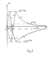
- the pressure then increases in the pneumatic system, ie in particular in the line 7 and the actuators 8 so that the actuators move the locks into the desired position. This increase in pressure is shown in Fig. 3 between t0 and t1 (a).
- the space 19 of the pressure switch - see FIG.
- the contact 17 closes at a differential overpressure of 5 times 104Pa and sends a corresponding signal via line 20 to the control electronics, which reverses the relay 4, so that the drive motor 5 now runs in the opposite direction after an intermediate stop, such that the air is drawn out of the pneumatic system and the air pressure therein drops rapidly.
- the upper tolerance threshold is reached, at which the pressure in the pneumatic system should correspond approximately to the ambient pressure.
- one of the lock switches 1 and 2 is set to ground potential, so that the drive motor 5 now starts or continues in a direction in which the pressure occurs through the line DSN between the control electronics 3 and the relay 4 and between the relay 4 and the drive motor is reduced in the pneumatic system.
- This pressure drop is shown in Fig. 3 again from t0 (c), up to the time t3 at which the differential vacuum is 5 times 104Pa. Due to this negative pressure, the membrane 11 is pressed so far into the space 19 by the action of the external air pressure that the contact spring 13 closes the working pressure contact 18.
- the ventilation pressure contact 16 was previously closed at smaller negative pressures.
- FIG. 3 the rapid ventilation process of the pneumatic system with the ventilation curves b - pressure drop during ventilation - and ventilation curve d - pressure increase during ventilation - compared to conventionally achieved ventilation curves b ⁇ and d ⁇ is illustrated.
- the ventilation of the pneu matical system along the ventilation curves b ⁇ and d ⁇ does not take place with the bidirectional pump operating at the rated speed or working speed in the opposite direction, but only after switching off the bidirectional pump when the corresponding working pressures have been reached.
- the pressure rise corresponding to curves a, a ⁇ and c, c ⁇ during the locking phase and unlocking phase has the same time profile in both comparative cases.
- the pneumatic system is thus vented in the shortest possible time, largely independently of the temperature and the pressure of the surrounding atmosphere.
- the pressure switch device includes not only the pressure switch but also the modified parts of the control electronics which switch over the drive motor in the manner described in accordance with the signals generated by the pressure switch.
Landscapes
- Engineering & Computer Science (AREA)
- Mechanical Engineering (AREA)
- General Engineering & Computer Science (AREA)
- Lock And Its Accessories (AREA)
- Air-Conditioning For Vehicles (AREA)
Applications Claiming Priority (2)
| Application Number | Priority Date | Filing Date | Title |
|---|---|---|---|
| DE3641276 | 1986-12-03 | ||
| DE19863641276 DE3641276A1 (de) | 1986-12-03 | 1986-12-03 | Anordnung zur steuerung eines drehrichtungsumkehrbaren elektrischen antriebs einer bidruckpumpe in einem pneumatischen system einer zentralverriegelungsanlage eines kraftfahrzeugs |
Publications (3)
| Publication Number | Publication Date |
|---|---|
| EP0269784A2 true EP0269784A2 (fr) | 1988-06-08 |
| EP0269784A3 EP0269784A3 (en) | 1988-10-19 |
| EP0269784B1 EP0269784B1 (fr) | 1989-09-20 |
Family
ID=6315352
Family Applications (1)
| Application Number | Title | Priority Date | Filing Date |
|---|---|---|---|
| EP87110198A Expired EP0269784B1 (fr) | 1986-12-03 | 1987-07-15 | Commande de moteur électrique réversible, pour pompe pour système de verrouillage central pneumatique pour véhicules |
Country Status (2)
| Country | Link |
|---|---|
| EP (1) | EP0269784B1 (fr) |
| DE (2) | DE3641276A1 (fr) |
Cited By (7)
| Publication number | Priority date | Publication date | Assignee | Title |
|---|---|---|---|---|
| FR2637702A1 (fr) * | 1988-10-11 | 1990-04-13 | Hella Kg Hueck & Co | Procede et dispositif de commande et controle de l'etat de marche d'un dispositif generateur de pression, notamment pour verrouillages centralises dans des vehicules automobiles |
| FR2647858A1 (fr) * | 1989-06-02 | 1990-12-07 | Daimler Benz Ag | Procede et appareillage pour enlever un condensat liquide d'un systeme a air comprime |
| US5040390A (en) * | 1989-11-16 | 1991-08-20 | General Motors Corporation | Lock and control assembly for a vehicle tailgate |
| EP0485875A1 (fr) * | 1990-11-14 | 1992-05-20 | Hella KG Hueck & Co. | Système de verrouillage central pour les serrures des portes et/ou clapets de véhicule automobile |
| EP0562277A1 (fr) * | 1992-03-25 | 1993-09-29 | Mercedes-Benz Ag | Méthode pour commander une installation centrale de verrouillage et installation centrale de verrouillage |
| FR2752310A1 (fr) * | 1996-08-09 | 1998-02-13 | Wabco France | Procede et dispositif de regulation de la pression d'un circuit de fluide |
| WO1998006945A1 (fr) * | 1996-08-09 | 1998-02-19 | Wabco France | Procede et dispositif de regulation de la pression d'un circuit de fluide et pompe a piston a cet effet |
Families Citing this family (3)
| Publication number | Priority date | Publication date | Assignee | Title |
|---|---|---|---|---|
| DE3912632C1 (en) * | 1989-04-18 | 1990-05-17 | Daimler-Benz Aktiengesellschaft, 7000 Stuttgart, De | Controlling central locking installation of motor vehicle - releasing control switch by key assigned to electrical signal combination recognition circuit |
| DE4234261C5 (de) * | 1992-10-10 | 2008-03-27 | Hella Kgaa Hueck & Co. | Türverriegelungseinrichtung für Kraftfahrzeuge |
| DE19734987A1 (de) * | 1997-08-13 | 1999-03-04 | Bosch Gmbh Robert | Druckschalter |
Family Cites Families (3)
| Publication number | Priority date | Publication date | Assignee | Title |
|---|---|---|---|---|
| DE3120778C2 (de) * | 1981-05-25 | 1985-05-02 | Vdo Adolf Schindling Ag, 6000 Frankfurt | Einrichtung zum Ent- und Verriegeln von Türen |
| DE3151010A1 (de) * | 1981-12-23 | 1983-07-28 | Robert Bosch Gmbh, 7000 Stuttgart | Verfahren zum betreiben eines vorzugsweise zu einer zentralverriegelungsanlage eines kraftfahrzeugs gehoerenden pneumatischen systems |
| DE3400945A1 (de) * | 1984-01-13 | 1985-07-25 | Robert Bosch Gmbh, 7000 Stuttgart | Zentralverriegelungsanlage eines kraftfahrzeugs |
-
1986
- 1986-12-03 DE DE19863641276 patent/DE3641276A1/de not_active Withdrawn
-
1987
- 1987-07-15 DE DE8787110198T patent/DE3760591D1/de not_active Expired
- 1987-07-15 EP EP87110198A patent/EP0269784B1/fr not_active Expired
Cited By (7)
| Publication number | Priority date | Publication date | Assignee | Title |
|---|---|---|---|---|
| FR2637702A1 (fr) * | 1988-10-11 | 1990-04-13 | Hella Kg Hueck & Co | Procede et dispositif de commande et controle de l'etat de marche d'un dispositif generateur de pression, notamment pour verrouillages centralises dans des vehicules automobiles |
| FR2647858A1 (fr) * | 1989-06-02 | 1990-12-07 | Daimler Benz Ag | Procede et appareillage pour enlever un condensat liquide d'un systeme a air comprime |
| US5040390A (en) * | 1989-11-16 | 1991-08-20 | General Motors Corporation | Lock and control assembly for a vehicle tailgate |
| EP0485875A1 (fr) * | 1990-11-14 | 1992-05-20 | Hella KG Hueck & Co. | Système de verrouillage central pour les serrures des portes et/ou clapets de véhicule automobile |
| EP0562277A1 (fr) * | 1992-03-25 | 1993-09-29 | Mercedes-Benz Ag | Méthode pour commander une installation centrale de verrouillage et installation centrale de verrouillage |
| FR2752310A1 (fr) * | 1996-08-09 | 1998-02-13 | Wabco France | Procede et dispositif de regulation de la pression d'un circuit de fluide |
| WO1998006945A1 (fr) * | 1996-08-09 | 1998-02-19 | Wabco France | Procede et dispositif de regulation de la pression d'un circuit de fluide et pompe a piston a cet effet |
Also Published As
| Publication number | Publication date |
|---|---|
| DE3760591D1 (en) | 1989-10-26 |
| EP0269784B1 (fr) | 1989-09-20 |
| DE3641276A1 (de) | 1988-06-16 |
| EP0269784A3 (en) | 1988-10-19 |
Similar Documents
| Publication | Publication Date | Title |
|---|---|---|
| EP3341253B1 (fr) | Frein de parquage électrique avec source auxiliaire d'énergie | |
| EP0269784B1 (fr) | Commande de moteur électrique réversible, pour pompe pour système de verrouillage central pneumatique pour véhicules | |
| EP0067950A2 (fr) | Commande de porte électropneumatique | |
| DE2717958A1 (de) | Antriebsvorrichtung fuer elektrische schaltgeraete mit druckkontakten | |
| DE102007056349B4 (de) | Fahrzeugtüranlage | |
| EP0309729A2 (fr) | Système d'alimentation à deux pressions dans un véhicule | |
| EP0446651B1 (fr) | Système d'actionnement électropneumatique de porte de véhicule de transport de passagers | |
| DE19502212C1 (de) | Elektropneumatischer Umformer | |
| EP0304542B1 (fr) | Dispositif de fermeture assisté pour porte de véhicule automobile | |
| DE3439613C2 (fr) | ||
| EP0163861A2 (fr) | Dispositif de manoeuvre de porte | |
| EP0398009B1 (fr) | Soupape de commutation pouvant être reliée à une soupape de régulation de niveau par un branchement de fluide de commande ou commandée électriquement | |
| DE3105867C2 (de) | Schaltungsanordnung für druckmittelbetätigte, insbesondere pneumatisch betätigte, Türen in Fahrzeugen, wie Omnibussen, Straßenbahnen o.dgl. | |
| EP0388805B1 (fr) | Dispositif de descente rapide de prises de courant à commande pneumatique pour véhicules à propulsion électrique | |
| DE3400945A1 (de) | Zentralverriegelungsanlage eines kraftfahrzeugs | |
| DE2524781A1 (de) | Minderdrucksicherung fuer pneumatisch betriebene anlagen | |
| DE3150564A1 (de) | "hin- und herbewegliches pneumatisches arbeitsorgan fuer zentralverriegelungsanlagen von fahrzeugen" | |
| EP0284654A2 (fr) | Dispositif de fermeture | |
| DE10016737A1 (de) | Vorrichtung zur Erzeugung eines Unterdrucks in einem Kraftfahrzeug | |
| DE3809591C2 (de) | Sicherheitsschaltung für elektrisch ansteuerbare Türantriebe in Fahrzeugen für Personenbeförderung | |
| DE3223016C2 (de) | Pneumatische Zentralverriegelungsanlage für die Türen, Klappen oder dergleichen eines Kraftfahrzeuges | |
| EP0257538A1 (fr) | Arrangement des interrupteurs dans des véhicules à moteur | |
| DE3803836A1 (de) | Einrichtung zum ent- und verriegeln von tueren, insbesondere kraftfahrzeugtueren | |
| WO2019211086A1 (fr) | Dispositif de commande et procédé de commande d'un lève-vitre muni d'une protection anti-pincement pour un véhicule automobile | |
| EP0450326A1 (fr) | Circuit de commande pour actionneurs d'éléments de fermeture pour véhicules automobiles |
Legal Events
| Date | Code | Title | Description |
|---|---|---|---|
| PUAI | Public reference made under article 153(3) epc to a published international application that has entered the european phase |
Free format text: ORIGINAL CODE: 0009012 |
|
| AK | Designated contracting states |
Kind code of ref document: A2 Designated state(s): DE FR GB IT |
|
| PUAL | Search report despatched |
Free format text: ORIGINAL CODE: 0009013 |
|
| AK | Designated contracting states |
Kind code of ref document: A3 Designated state(s): DE FR GB IT |
|
| 17P | Request for examination filed |
Effective date: 19880903 |
|
| 17Q | First examination report despatched |
Effective date: 19890227 |
|
| GRAA | (expected) grant |
Free format text: ORIGINAL CODE: 0009210 |
|
| AK | Designated contracting states |
Kind code of ref document: B1 Designated state(s): DE FR GB IT |
|
| REF | Corresponds to: |
Ref document number: 3760591 Country of ref document: DE Date of ref document: 19891026 |
|
| ET | Fr: translation filed | ||
| ITF | It: translation for a ep patent filed | ||
| GBT | Gb: translation of ep patent filed (gb section 77(6)(a)/1977) | ||
| PGFP | Annual fee paid to national office [announced via postgrant information from national office to epo] |
Ref country code: FR Payment date: 19900619 Year of fee payment: 4 |
|
| PLBE | No opposition filed within time limit |
Free format text: ORIGINAL CODE: 0009261 |
|
| STAA | Information on the status of an ep patent application or granted ep patent |
Free format text: STATUS: NO OPPOSITION FILED WITHIN TIME LIMIT |
|
| 26N | No opposition filed | ||
| PG25 | Lapsed in a contracting state [announced via postgrant information from national office to epo] |
Ref country code: GB Effective date: 19910715 |
|
| ITTA | It: last paid annual fee | ||
| GBPC | Gb: european patent ceased through non-payment of renewal fee | ||
| PG25 | Lapsed in a contracting state [announced via postgrant information from national office to epo] |
Ref country code: FR Effective date: 19920331 |
|
| REG | Reference to a national code |
Ref country code: FR Ref legal event code: ST |
|
| PGFP | Annual fee paid to national office [announced via postgrant information from national office to epo] |
Ref country code: DE Payment date: 19940603 Year of fee payment: 8 |
|
| PG25 | Lapsed in a contracting state [announced via postgrant information from national office to epo] |
Ref country code: DE Effective date: 19960402 |
|
| PG25 | Lapsed in a contracting state [announced via postgrant information from national office to epo] |
Ref country code: IT Free format text: LAPSE BECAUSE OF NON-PAYMENT OF DUE FEES;WARNING: LAPSES OF ITALIAN PATENTS WITH EFFECTIVE DATE BEFORE 2007 MAY HAVE OCCURRED AT ANY TIME BEFORE 2007. THE CORRECT EFFECTIVE DATE MAY BE DIFFERENT FROM THE ONE RECORDED. Effective date: 20050715 |