EP0269816A2 - Zylindrische Plattenhalterhülse für lithographische Druckmaschinen mit abnehmbaren Hülsen, insbesondere zum Drucken auf zylindrische Körper und dergleichen - Google Patents
Zylindrische Plattenhalterhülse für lithographische Druckmaschinen mit abnehmbaren Hülsen, insbesondere zum Drucken auf zylindrische Körper und dergleichen Download PDFInfo
- Publication number
- EP0269816A2 EP0269816A2 EP87115048A EP87115048A EP0269816A2 EP 0269816 A2 EP0269816 A2 EP 0269816A2 EP 87115048 A EP87115048 A EP 87115048A EP 87115048 A EP87115048 A EP 87115048A EP 0269816 A2 EP0269816 A2 EP 0269816A2
- Authority
- EP
- European Patent Office
- Prior art keywords
- skirt
- plate
- printing
- cylindrical
- arch
- Prior art date
- Legal status (The legal status is an assumption and is not a legal conclusion. Google has not performed a legal analysis and makes no representation as to the accuracy of the status listed.)
- Granted
Links
- 239000003086 colorant Substances 0.000 claims abstract description 11
- 238000000034 method Methods 0.000 claims abstract description 11
- 238000004080 punching Methods 0.000 claims abstract description 8
- 238000004873 anchoring Methods 0.000 claims 1
- 230000003287 optical effect Effects 0.000 description 4
- 229910052751 metal Inorganic materials 0.000 description 2
- 239000002184 metal Substances 0.000 description 2
- 238000012986 modification Methods 0.000 description 2
- 230000004048 modification Effects 0.000 description 2
- FYYHWMGAXLPEAU-UHFFFAOYSA-N Magnesium Chemical compound [Mg] FYYHWMGAXLPEAU-UHFFFAOYSA-N 0.000 description 1
- 229910000831 Steel Inorganic materials 0.000 description 1
- HCHKCACWOHOZIP-UHFFFAOYSA-N Zinc Chemical compound [Zn] HCHKCACWOHOZIP-UHFFFAOYSA-N 0.000 description 1
- 238000005452 bending Methods 0.000 description 1
- 230000002452 interceptive effect Effects 0.000 description 1
- 229910052749 magnesium Inorganic materials 0.000 description 1
- 239000011777 magnesium Substances 0.000 description 1
- 239000000463 material Substances 0.000 description 1
- 238000002360 preparation method Methods 0.000 description 1
- 230000003252 repetitive effect Effects 0.000 description 1
- 239000007787 solid Substances 0.000 description 1
- 239000010959 steel Substances 0.000 description 1
- 239000000126 substance Substances 0.000 description 1
- 229910052725 zinc Inorganic materials 0.000 description 1
- 239000011701 zinc Substances 0.000 description 1
Images
Classifications
-
- B—PERFORMING OPERATIONS; TRANSPORTING
- B41—PRINTING; LINING MACHINES; TYPEWRITERS; STAMPS
- B41F—PRINTING MACHINES OR PRESSES
- B41F27/00—Devices for attaching printing elements or formes to supports
- B41F27/12—Devices for attaching printing elements or formes to supports for attaching flexible printing formes
- B41F27/1218—Devices for attaching printing elements or formes to supports for attaching flexible printing formes comprising printing plate tensioning devices
-
- B—PERFORMING OPERATIONS; TRANSPORTING
- B41—PRINTING; LINING MACHINES; TYPEWRITERS; STAMPS
- B41F—PRINTING MACHINES OR PRESSES
- B41F27/00—Devices for attaching printing elements or formes to supports
- B41F27/12—Devices for attaching printing elements or formes to supports for attaching flexible printing formes
- B41F27/1218—Devices for attaching printing elements or formes to supports for attaching flexible printing formes comprising printing plate tensioning devices
- B41F27/1256—Devices for attaching printing elements or formes to supports for attaching flexible printing formes comprising printing plate tensioning devices with two semi-cylinders movable relative to each other
-
- B—PERFORMING OPERATIONS; TRANSPORTING
- B41—PRINTING; LINING MACHINES; TYPEWRITERS; STAMPS
- B41F—PRINTING MACHINES OR PRESSES
- B41F27/00—Devices for attaching printing elements or formes to supports
- B41F27/14—Devices for attaching printing elements or formes to supports for attaching printing formes to intermediate supports, e.g. adapter members
Definitions
- the present invention relates to a plate-holder cylindrical skirt for printing presses for the lithographic printing on cylindrical bodies, and the like, and, more precisely, for printing presses of the removable-skirt type.
- the lithographic printing presses for printing on cylindrical bodies use a plurality of mould- or plate-holder cylindrical bodies (skirts); in substance, the plates are constituted by metal sheets (of steel, magnesium, zinc, and so forth), on which the images or characters to be printed on paper, or on the surfaces of solid bodies are obtained by photoengraving by starting from a photographic print exposed in negative and then developed in positive.
- the printing presses use a number of plates, and therefore, a number of cylindrical skirts equal to the number of the colours which compose the full-colour image; in general, the plate-holder skirts are positioned according to the generatrices of a cylinder, and into contact with a roller, whose external surface is coated with rubber, or with a similar material; the plates are then inked up, in continuous, by special wavers-ink distributor rollers, which draw ink from suitable ink containers.
- the portion of coloured image having the colour carried by each roller is sequentially transferred on the rubber-coated roller, and from this latter to the outer surface of the cylindrical bodies on which the total image is transferred.
- each plate on its respective skirt is carried out by using optical systems which make it possible, by means of reference points correspondingly shown on all of the plates, the individual plates to be brought into register on their respective skirts.
- two small crosses, or similar marks are provided, which are suitably spaced apart from each other along a side edge of the same film.
- Such reference marks or crosses are then transferred, during the development, on the positive film, and from this latter, by photoengraving, on the metal plate which constitutes the plate.
- two bars are then fastened by means of screws, which clamp, between each other, the edge of the plate, and are used to anchor the plate round the outer surface of the cylindrical skirt.
- the fixing of the bars onto the skirt is carried out by hooking the opposite ends of said bars to the ends of four arch-shaped, crescent-shape elements, hinged onto the two head ends of the skirt.
- each plate-holder skirt is positioned inside an optical-type equipment, able to determine fixed reference points with which the reference crosses engraved on the plates have to be made coincide.
- the bringing into register is carried out by acting on screws associated with the skirt and acting on a bar fastened onto a plate side; one of such screws is prearranged to shift the plate, by a short distance, along the generatrices of the cylindrical skirt, and the other screw is prearranged to shift the plate, by a short distance, along the directrices of the same skirt.
- the adjustment is stopped when the reference crosses on the plate coincide with the fixed reference points of the optical system.
- a purpose of the present invention is to provide a plate-holder skirt having such a structure as not to require the plates to be brought into register on their respective skirts by means of an optical equipment, to allow a considerable saving, ranging from one to two, or even more hours, to be achieved in the time required by the processes of positioning and centering of the plates, and hence with the advantage that orders for the lithographic printing of even small amounts can be accepted.
- Another purpose of the present invention is to provide a plate-holder skirt able to result interchangeable with the skirts known from the prior art, and, hence, to be installed on the printing presses of known type, without any modifications thereof being necessary and, above all, without requiring the use of specialized staff.
- a plate-holder skirt for lithographic printing presses of removable-skirt type particularly suitable for the many-colours printing on cylindrical bodies, or the like, and provided at its ends with usual engagement means, to be fastened onto, to revolve with the revolving shaft of the printing press,
- skirt is constituted, according to the instant invention: - by an internally hollow cylindrical body, provided along one of its generatrices, and in the nearby of the longitudinal slot, provided to enable it to be positioned on the printing press revolving shaft, with at least three radially protruding pins, suitable for being engaged inside three corresponding holes provided on one side edge of the photoengraved plate, and provided, during the photoengraving process, by a punching preliminarily carried out, in a corresponding position, on all of the plates which constitute the many-colours image to be printed, such that said image is always equally positioned relatively to said three holes provided on the plates, - by at least a
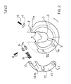
- the plate-holder skirt is substantially constituted, as in the types known from the prior art, by a cylindrical body 1 provided, at its opposite ends, with two inner and coaxial seats 2 suitable for being positioned on the revolving shaft of a lithographic printing press of the removable-skirt type, with the relevant fastening taking place by means of keys, or the like, inserted inside the radial seats 3 (see Figure 2).
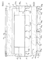
- a plate 4 (see Figure 1) is wound and laid round the outer surface of the skirt 1, with such positioning and centering on the same skirt that during the overlapping of the various plates to the rubber-coated, image transfer roller, a perfect matching is obtained in the position of the different colour patterns of all of the concerned plates.
- the same plates 4 ( Figure 1) are preliminarily provided with reference elements able to make it possible the same plates to be automatically positioned and centered on their related skirt, with no need for any subsequent adjustments.
- the holes provided on the plates 4 are then preferably given a non-circular shape; e.g., by giving the external holes 5 and 6 an elongated configuration, with the long axis parallel to the generatrices of the cylinder 1, and giving the central hole 7 an elongated configuration, with the long axis perpendicular to the generatrices of the cylinder 1.
- the pins provided on the skirt are realized radially protruding from the skirt and are positioned along a generatrix of the cylindrical body 1 which is close to the usual slot 9 longitudinally provided on the skirt, to make it possible the same skirt to be inserted on, and removed from, the printing press shaft.
- the three pins 8 are positioned on a surface portion 1a which is lowered relatively to the cylindrical surface of the skirt, so to prevent the pins from interfering with the image transfer rubber-coated roller.
- the skirt 1 is then equipped, at its opposite ends, with an arch-shaped, crescent-shaped element 10, and, respectively 10a; the arch-shaped elements 10, 10a are hinged in 11 on the two front heads of the skirt 1, so that they can be opened wide, on the plane of the same heads, towards the outside of the cylindrical surface of the skirt and then turned until they come to mate the same heads, and are fastened onto said heads by means of screws passing through bores 12, 12a.
- the hinging of the arch-shaped elements is carried out by means of a single shaft passing through the skirt and rotatable on it, at whose ends the arch-shaped elements are integral in 11; in such a way, when one acts on one of the two arch-shaped elements, the turning of the opposite arch-shaped element is also obtained.
- a fork-shaped recess 13, and, respectively, 13a is provided; its function will be clarified in the following.
- a hollow 14a is provided, which is destined to house a cylindrical or helical spring 14, whose function is also clarified in the following.
- the centered positioning of a plate 4 on the skirt 1 is therefore carried out by sliding the holes 5, 6, 7 on the pins 8 of the skirt, and clamping the plate on the same skirt by means of a bar 15, which is also provided with holes 15a in positions corresponding to the positions of the pins 8 and which, in its turn, is fastened to the skirt by means of screws 16, passing through the bar in 16a, and the underlying plate 4, and engaged inside the screw-threaded bores 16b provided on the skirt.
- the plate 4 is laid on the skirt, and the spring 14, inserted inside the hollow 14a, and into contact with the free end of the bar 17-17a inserted inside the fork 13, contributes to control the tension of the plate during the printing process. Therefore, in practice, the presence, as reference points, of holes equally positioned on all of the plates forming the many-colours image, and their sliding on the retainer pins provided on the skirt, causes an automatic and corresponding positioning of all of the plates on their respective skirts, the control of the tensioning of the plates being guaranteed by the spring tensioning system provided at the end of the arch-shaped elements 10, 10a.
- the skirt according to the invention is so realized as not to have sharp edges in the plate bending areas, in order to prevent sharp-edge bends - which would cause difficulties in the bringing into register and in the adjustment - from occurring in the same plates.
- skirt as above disclosed is then installed on the printing press, as in case of the skirts of type known from the prior art, i.e., making protrusions, provided for that purpose, enter corresponding hollows provided on skirt supports, and by means of the above mentioned radial keys 3 ( Figure 2).
- the subject skirt of the present invention results interchangeable with the skirts known from the prior art and is hence directly installable on the already existing printing presses, with no modifications.
Landscapes
- Printing Plates And Materials Therefor (AREA)
- Manufacture Or Reproduction Of Printing Formes (AREA)
- Supply, Installation And Extraction Of Printed Sheets Or Plates (AREA)
- Handcart (AREA)
- Exposure And Positioning Against Photoresist Photosensitive Materials (AREA)
- Discharging, Photosensitive Material Shape In Electrophotography (AREA)
- Photosensitive Polymer And Photoresist Processing (AREA)
- Coating Apparatus (AREA)
Applications Claiming Priority (2)
| Application Number | Priority Date | Filing Date | Title |
|---|---|---|---|
| IT2254786 | 1986-12-03 | ||
| IT22547/86A IT1199685B (it) | 1986-12-03 | 1986-12-03 | Mantello cilindrico porta-cliche'per macchine da stampa litografiche a mantelli estraibili,particolarmente per la stampa su corpi cilindrici e simili |
Publications (3)
| Publication Number | Publication Date |
|---|---|
| EP0269816A2 true EP0269816A2 (de) | 1988-06-08 |
| EP0269816A3 EP0269816A3 (en) | 1989-12-20 |
| EP0269816B1 EP0269816B1 (de) | 1994-06-01 |
Family
ID=11197697
Family Applications (1)
| Application Number | Title | Priority Date | Filing Date |
|---|---|---|---|
| EP87115048A Expired - Lifetime EP0269816B1 (de) | 1986-12-03 | 1987-10-15 | Zylindrische Plattenhalterhülse für lithographische Druckmaschinen mit abnehmbaren Hülsen, insbesondere zum Drucken auf zylindrische Körper und dergleichen |
Country Status (4)
| Country | Link |
|---|---|
| EP (1) | EP0269816B1 (de) |
| AT (1) | ATE106319T1 (de) |
| DE (1) | DE3789939T2 (de) |
| IT (1) | IT1199685B (de) |
Cited By (3)
| Publication number | Priority date | Publication date | Assignee | Title |
|---|---|---|---|---|
| US5345868A (en) * | 1993-06-04 | 1994-09-13 | Baker A Leroy | Printing plate mounting support and method |
| US5361698A (en) * | 1992-02-21 | 1994-11-08 | Man Roland Druckmaschinen Ag | Device for clamping a printing plate onto a plate cylinder |
| USRE35647E (en) * | 1992-04-02 | 1997-11-04 | Man Roland Druckmaschinen Ag | Plate cylinder holder with slide rail circular bearing assembly |
Family Cites Families (5)
| Publication number | Priority date | Publication date | Assignee | Title |
|---|---|---|---|---|
| US2970540A (en) * | 1958-09-16 | 1961-02-07 | Miehle Goss Dexter Inc | Saddle for supporting thin printing plates |
| BE733564A (de) * | 1968-06-24 | 1969-11-03 | ||
| IT1028331B (it) * | 1974-01-14 | 1979-01-30 | Houdaille Industries Inc | Dispositivo di bloccaggio per sel la e lastra da stampa per essa |
| US4259904A (en) * | 1979-07-23 | 1981-04-07 | Heinz Metje | Alignment system for offset printing presses |
| GB2167712B (en) * | 1984-11-30 | 1989-06-01 | Grapho Metronic Gmbh & Co | Plate cylinder of a printing machine including a device for clamping and adjusting a print plate thereon |
-
1986
- 1986-12-03 IT IT22547/86A patent/IT1199685B/it active
-
1987
- 1987-10-15 AT AT87115048T patent/ATE106319T1/de not_active IP Right Cessation
- 1987-10-15 DE DE3789939T patent/DE3789939T2/de not_active Expired - Fee Related
- 1987-10-15 EP EP87115048A patent/EP0269816B1/de not_active Expired - Lifetime
Cited By (3)
| Publication number | Priority date | Publication date | Assignee | Title |
|---|---|---|---|---|
| US5361698A (en) * | 1992-02-21 | 1994-11-08 | Man Roland Druckmaschinen Ag | Device for clamping a printing plate onto a plate cylinder |
| USRE35647E (en) * | 1992-04-02 | 1997-11-04 | Man Roland Druckmaschinen Ag | Plate cylinder holder with slide rail circular bearing assembly |
| US5345868A (en) * | 1993-06-04 | 1994-09-13 | Baker A Leroy | Printing plate mounting support and method |
Also Published As
| Publication number | Publication date |
|---|---|
| EP0269816B1 (de) | 1994-06-01 |
| IT8622547A1 (it) | 1988-06-03 |
| IT8622547A0 (it) | 1986-12-03 |
| ATE106319T1 (de) | 1994-06-15 |
| IT1199685B (it) | 1988-12-30 |
| DE3789939D1 (de) | 1994-07-07 |
| DE3789939T2 (de) | 1994-09-08 |
| EP0269816A3 (en) | 1989-12-20 |
Similar Documents
| Publication | Publication Date | Title |
|---|---|---|
| US4421027A (en) | Multiple printing mode printing machine system | |
| US3154012A (en) | Means for registering printing plates | |
| US4380956A (en) | Mounting of flexible printing plates | |
| AU738241B2 (en) | Rotary printing machine for security papers | |
| SU1431667A3 (ru) | Многокрасочна листова или ролева ротационна печатна машина | |
| US4441423A (en) | Collect-printing unit for security printing for use in a rotary printing press | |
| CA1200717A (en) | Apparatus for mounting flexible printing plates | |
| US4479431A (en) | Collect-printing unit for security printing for use in a rotary printing press | |
| DE58906399D1 (de) | Konvertierbare Mehrfarben-Druckmaschine zum Schön- und Widerdruck, insbesondere von Banknoten. | |
| US2118238A (en) | Multicolor rotary proof press | |
| US4860650A (en) | Method for attaining longitudinal registry of rolls in printing presses | |
| EP0269816A2 (de) | Zylindrische Plattenhalterhülse für lithographische Druckmaschinen mit abnehmbaren Hülsen, insbesondere zum Drucken auf zylindrische Körper und dergleichen | |
| US2236000A (en) | Method for registering printing plates | |
| US3160094A (en) | Method of rough registration for reprinting on a flexographic printing press | |
| US3108538A (en) | Flexible-printing-plate securing arrangement | |
| US4641577A (en) | Apparatus for adjusting the plate segment of an off-set lithographic printer | |
| US4707902A (en) | Mechanism for accurate register alignment of a blanket on a blanket or plate cylinder | |
| US3347161A (en) | Method and apparatus for registering and making-ready printing plates off a press | |
| DE59400808D1 (de) | Vorrichtung zum passgenauen Spannen von Druckplatten auf dem Plattenzylinder von Druckmaschinen | |
| US4932322A (en) | Swing away color head for offset duplicator | |
| JPH06206301A (ja) | 画像転写装置 | |
| US3366046A (en) | Printing cylinder with ink belts for multicolor single impression printing | |
| US2927528A (en) | Code printing machine | |
| US4896599A (en) | Swing-away colorhead for offset duplicator | |
| SU859203A1 (ru) | Способ приладки гибких печатных форм в многокрасочной рулонной ротационной машине |
Legal Events
| Date | Code | Title | Description |
|---|---|---|---|
| PUAI | Public reference made under article 153(3) epc to a published international application that has entered the european phase |
Free format text: ORIGINAL CODE: 0009012 |
|
| AK | Designated contracting states |
Kind code of ref document: A2 Designated state(s): AT BE CH DE ES FR GB GR LI LU NL SE |
|
| PUAL | Search report despatched |
Free format text: ORIGINAL CODE: 0009013 |
|
| AK | Designated contracting states |
Kind code of ref document: A3 Designated state(s): AT BE CH DE ES FR GB GR LI LU NL SE |
|
| 17P | Request for examination filed |
Effective date: 19900511 |
|
| 17Q | First examination report despatched |
Effective date: 19920116 |
|
| 18D | Application deemed to be withdrawn |
Effective date: 19930119 |
|
| 18RA | Request filed for re-establishment of rights before grant |
Effective date: 19931026 |
|
| D18D | Application deemed to be withdrawn (deleted) | ||
| GRAA | (expected) grant |
Free format text: ORIGINAL CODE: 0009210 |
|
| AK | Designated contracting states |
Kind code of ref document: B1 Designated state(s): AT BE CH DE ES FR GB GR LI LU NL SE |
|
| PG25 | Lapsed in a contracting state [announced via postgrant information from national office to epo] |
Ref country code: CH Effective date: 19940601 Ref country code: NL Effective date: 19940601 Ref country code: LI Effective date: 19940601 Ref country code: GR Free format text: LAPSE BECAUSE OF FAILURE TO SUBMIT A TRANSLATION OF THE DESCRIPTION OR TO PAY THE FEE WITHIN THE PRESCRIBED TIME-LIMIT Effective date: 19940601 |
|
| REF | Corresponds to: |
Ref document number: 106319 Country of ref document: AT Date of ref document: 19940615 Kind code of ref document: T |
|
| REF | Corresponds to: |
Ref document number: 3789939 Country of ref document: DE Date of ref document: 19940707 |
|
| ET | Fr: translation filed | ||
| PG25 | Lapsed in a contracting state [announced via postgrant information from national office to epo] |
Ref country code: SE Effective date: 19940901 |
|
| PG25 | Lapsed in a contracting state [announced via postgrant information from national office to epo] |
Ref country code: ES Free format text: LAPSE BECAUSE OF FAILURE TO SUBMIT A TRANSLATION OF THE DESCRIPTION OR TO PAY THE FEE WITHIN THE PRESCRIBED TIME-LIMIT Effective date: 19940912 |
|
| REG | Reference to a national code |
Ref country code: CH Ref legal event code: PL |
|
| PG25 | Lapsed in a contracting state [announced via postgrant information from national office to epo] |
Ref country code: GB Effective date: 19941015 |
|
| PG25 | Lapsed in a contracting state [announced via postgrant information from national office to epo] |
Ref country code: LU Free format text: LAPSE BECAUSE OF NON-PAYMENT OF DUE FEES Effective date: 19941031 |
|
| NLV1 | Nl: lapsed or annulled due to failure to fulfill the requirements of art. 29p and 29m of the patents act | ||
| PLBE | No opposition filed within time limit |
Free format text: ORIGINAL CODE: 0009261 |
|
| STAA | Information on the status of an ep patent application or granted ep patent |
Free format text: STATUS: NO OPPOSITION FILED WITHIN TIME LIMIT |
|
| 26N | No opposition filed | ||
| GBPC | Gb: european patent ceased through non-payment of renewal fee |
Effective date: 19941015 |
|
| PGFP | Annual fee paid to national office [announced via postgrant information from national office to epo] |
Ref country code: BE Payment date: 19950807 Year of fee payment: 9 |
|
| PGFP | Annual fee paid to national office [announced via postgrant information from national office to epo] |
Ref country code: FR Payment date: 19960917 Year of fee payment: 10 |
|
| PGFP | Annual fee paid to national office [announced via postgrant information from national office to epo] |
Ref country code: DE Payment date: 19961028 Year of fee payment: 10 Ref country code: AT Payment date: 19961028 Year of fee payment: 10 |
|
| PG25 | Lapsed in a contracting state [announced via postgrant information from national office to epo] |
Ref country code: BE Effective date: 19961031 |
|
| BERE | Be: lapsed |
Owner name: TUBETTIFICIO EUROPEO S.P.A. Effective date: 19961031 |
|
| PG25 | Lapsed in a contracting state [announced via postgrant information from national office to epo] |
Ref country code: AT Free format text: LAPSE BECAUSE OF NON-PAYMENT OF DUE FEES Effective date: 19971015 |
|
| PG25 | Lapsed in a contracting state [announced via postgrant information from national office to epo] |
Ref country code: FR Free format text: THE PATENT HAS BEEN ANNULLED BY A DECISION OF A NATIONAL AUTHORITY Effective date: 19971031 |
|
| PG25 | Lapsed in a contracting state [announced via postgrant information from national office to epo] |
Ref country code: DE Free format text: LAPSE BECAUSE OF NON-PAYMENT OF DUE FEES Effective date: 19980701 |
|
| REG | Reference to a national code |
Ref country code: FR Ref legal event code: ST |