EP0269895A2 - Filtre pour liquide, en particulier pour carburants - Google Patents
Filtre pour liquide, en particulier pour carburants Download PDFInfo
- Publication number
- EP0269895A2 EP0269895A2 EP87116220A EP87116220A EP0269895A2 EP 0269895 A2 EP0269895 A2 EP 0269895A2 EP 87116220 A EP87116220 A EP 87116220A EP 87116220 A EP87116220 A EP 87116220A EP 0269895 A2 EP0269895 A2 EP 0269895A2
- Authority
- EP
- European Patent Office
- Prior art keywords
- housing
- liquid filter
- collar
- sealing
- annular space
- Prior art date
- Legal status (The legal status is an assumption and is not a legal conclusion. Google has not performed a legal analysis and makes no representation as to the accuracy of the status listed.)
- Granted
Links
Images


Classifications
-
- B—PERFORMING OPERATIONS; TRANSPORTING
- B01—PHYSICAL OR CHEMICAL PROCESSES OR APPARATUS IN GENERAL
- B01D—SEPARATION
- B01D27/00—Cartridge filters of the throw-away type
- B01D27/04—Cartridge filters of the throw-away type with cartridges made of a piece of unitary material, e.g. filter paper
- B01D27/06—Cartridge filters of the throw-away type with cartridges made of a piece of unitary material, e.g. filter paper with corrugated, folded or wound material
- B01D27/07—Cartridge filters of the throw-away type with cartridges made of a piece of unitary material, e.g. filter paper with corrugated, folded or wound material having a coaxial stream through the filtering element
-
- B—PERFORMING OPERATIONS; TRANSPORTING
- B01—PHYSICAL OR CHEMICAL PROCESSES OR APPARATUS IN GENERAL
- B01D—SEPARATION
- B01D27/00—Cartridge filters of the throw-away type
- B01D27/08—Construction of the casing
-
- B—PERFORMING OPERATIONS; TRANSPORTING
- B01—PHYSICAL OR CHEMICAL PROCESSES OR APPARATUS IN GENERAL
- B01D—SEPARATION
- B01D2201/00—Details relating to filtering apparatus
- B01D2201/34—Seals or gaskets for filtering elements
Definitions
- the invention relates to a liquid filter according to the preamble of the main claim.
- a liquid filter for cleaning fuels is already known from DE-PS 25 47 904, in which an axially flow wound filter insert is arranged in a two-part housing consisting of a cup-shaped housing part and an associated cover part and both parts of the housing are flanged together at their edges are.
- This type of filter has a first sealing point between the inner wall of the housing and the outer surface of the wound filter insert, which separates a dirt side from a clean side, while the seal from the inside of the housing to the outside assumes a second sealing point in the flanged edges.
- the disadvantage of this design is that it has two separate sealing points, which must also consist of a fuel-resistant adhesive. This leads to a relatively complex construction, which is due in particular to the handling of the adhesive in production. Furthermore, there is a risk of leakage problems if hair cracks occur in the adhesive bond between the wound filter insert and the metal housing in extreme conditions.
- a liquid filter is known, the housing of which consists of a cup-shaped housing part and a cover part accommodates a filter insert in the form of a star filter.
- Adhesive-free seals using O-rings are already provided here in order to separate the inside of the housing from the outside or a dirt side from a clean side.
- a disadvantage of this type of construction is that two sealing points that are spatially separated from one another are required for these sealing functions. Furthermore, this type of O-ring seal cannot be transferred to a filter with a wound filter insert.
- the liquid filter according to the invention with the characterizing features of the main claim has the advantage that it enables a seal that is as adhesive-free as possible in a simple and inexpensive manner.
- Two sealing functions are performed by a single sealing ring, which seals both in the radial and in the axial direction, in order to separate the inside of the housing from the outside and, on the other hand, a dirt side from a clean side.
- the adhesive-free seal leads to a more cost-effective solution and to a more environmentally friendly manufacturing process, since there is no need for gluing between the wound filter insert and the metallic housing wall. This also eliminates the need for degreasing.
- the ring-shaped collar also molded onto the wound filter insert leads to greater dimensional stability and thus facilitates handling of the wound filter insert.
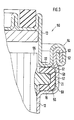
- FIG. 1 shows a partial longitudinal section through a first embodiment of the liquid filter and FIGS. 2 and 3 each show longitudinal sections through part of a second and third embodiment of the liquid filter.
- FIG. 1 shows a liquid filter 10 in line filter type, with an essentially two-part housing 11, which consists of a cup-shaped housing part 12 and an associated cover part 13.
- a connector 14 for the inlet and a connector 15 for the outlet are arranged on the cover part 13 and on the housing part 12.
- Housing part 12 and cover part 13 are firmly connected to one another at their edges by a crimping point 16.
- the cup-shaped housing part 12 has in the vicinity of the crimping point 16 a shoulder 19 which extends radially outwards with respect to the longitudinal axis of the liquid filter 10 and which is followed by a widened wall section 21 which runs coaxially to the longitudinal axis and which in turn then in the flanged edge 17 of the Housing part 12 merges.
- the cantilevered edge 18 of the cover part 13 forms in the diameter region of the shoulder 19 a flat, radially extending wall region 22 which, together with the wall section 21 and the shoulder 19, delimits an annular space 23 which is open towards the interior of the housing 11.
- the housing 11 accommodates a winding filter insert 24, known per se, which is flowed through axially.
- a winding filter insert 24 known per se, which is flowed through axially.
- a filter paper strip with a V-shaped cross-section is spirally wound around a central tube 25 with the addition of a sealing strip in such a way that it forms two spiral-shaped spaces which are open towards opposite end faces.
- the wound filter insert 24 is supported, on the one hand, by ribs (not shown) in the cup-shaped housing part 12 and, on the other hand, by a cap 26 closing the central tube 25 on the cover part 13.
- a dimensionally stable, annular collar 28 is formed on an outer lateral surface 27 of the wound filter insert 24 at the level of the annular space 23.
- This collar 28 consists of a pure polyamide and is injection molded onto the outer circumference of the wound filter element 24 and is also shaped in a circular shape in such a way that it forms a smooth, cylindrical sealing surface 29 on the outside, which essentially delimits the annular space 23 on its side which is open towards the interior of the housing.
- the annular collar 28 gives the wound filter insert 24 greater dimensional stability, which is additionally reinforced as required by a metal ring 31 injected into the collar 28.
- the sealing surface 29 can fulfill its tasks if the radial thickness of the collar 28 is kept relatively small, which in turn allows a compact design and good use of the interior.
- the circumferential annular space 23 formed in this way in the vicinity of the crimping point 16 in this way has an essentially square cross section and receives an O-ring 32 which takes over the various sealing functions.
- This O-ring 32 abuts the sealing surface 29 and thus separates the dirt side assigned to the connecting piece 14 from the ring side assigned to the connecting piece 15.
- the O-ring 32 bears in the wall area 22 on the cover part 13 and at least in the wall section 21 on the housing part 12, so that the interior of the housing 11 is also sealed off from the outside and no liquid can escape via the flanging point 16.
- the O-ring 32 embodied here as a soft rubber sealing ring thus seals in the radial and in the axial direction, so that two sealing functions in the liquid filter 10 are achieved with a single sealing ring 32.
- the mode of operation of the liquid filter 10, in which the fuel to be cleaned is supplied to the connecting piece 14, flows axially through the wound filter element 24 and emerges cleanly at the connecting piece 15, is known per se, so that there is no need to go into this in detail.
- the liquid filter 10 is used particularly for cleaning fuels such as gasoline or diesel oil.
- FIG. 2 shows a longitudinal section through part of a second liquid filter 40, which differs from the first liquid filter 10 according to FIG. 1 as follows, the same reference numerals being used for the same components.
- the second liquid filter 40 has a wound filter insert 41, which in principle has the same structure, on which a dimensionally stable, annular collar 42 is formed on the lateral surface 27 near an end, the width of which extends in the radial direction is now larger.
- This collar 42 now lies with its one side 43 on the shoulder 19 of the housing part 12 and forms with its opposite side a radially extending, flat sealing surface 44 which borders on the annular space 23. While the axially extending wall section 21 and the radially extending wall area 22 border on the annular space 23 as before, it is delimited on its fourth side by a peripheral surface 45 of a perforated end plate 46, which is inside the housing 11 between the cover part 13 and the end face of the Coil filter insert 41 is arranged.
- the annular space 23 delimited in this way has a square cross section and receives an O-ring 47 as a sealing ring.
- the molded on the wound filter insert 41 collar 42 has a radial width which is greater than the diameter of the O-ring 47. In addition, its outer diameter is smaller than the inner diameter of the wall portion 21 so that the wound filter insert 41 easily in the cup-shaped housing part 12 can be used.
- the collar 42 can, as in FIG. 1, consist of plastic and be molded onto the wound filter insert 41, whereby the latter (41) achieves greater dimensional stability.
- the mode of operation of the second liquid filter 40 corresponds to that of the first filter 10.
- the O-ring 47 which in this case seals in the radial and in the axial direction, in turn takes on two sealing functions in that, by its contact with the sealing surface 44 of the collar 42, the dirty and clean side in the filter 40 separates from one another and at the same time seals the inside of the housing 11 from the outside by its abutment on the wall section 21 and the radially extending wall area 22.
- the assembly of the individual parts of the second liquid filter 40 is relatively simple.
- the winding filter insert 41 is inserted into the still open housing part 12, whereby its collar 42 essentially centers it in the housing part 12.
- the O-ring 47 can be placed on the sealing surface 44, wherein it is additionally held in its position by the inserted end plate 46.
- the edge 17 is flanged, the dimensional accuracy of the annular space 23 being maintained to such an extent that the O-ring 47 can perform its sealing functions perfectly.
- FIG. 3 shows a longitudinal section through part of a third liquid filter 50, which differs from the first liquid filter 10 according to FIG. 1 as follows, the same components being provided with the same reference numerals.
- annular space 51 is formed as before by a shoulder 19 and a wall section 21 of the cup-shaped housing 12 and by a radially extending region 22 of the cover part 13.
- the edges 52, 53 of both components 12, 13 are now connected to one another by a double flange 54, which - seen in the longitudinal axis of the liquid filter 50 - extends next to the annular space 51 towards the cover part 13.
- the wound filter insert 55 installed in the filter 50 now has an externally molded, dimensionally stable, annular collar 56 which projects centrally into the annular space 51 in such a way that a free, U-shaped cross section remains.
- This cross section is now filled by a rubber sleeve 57, which is formed in a U-shaped manner.
- the rubber sleeve 57 made of soft rubber encloses with its inner surface 58 the collar 56, which has a substantially rectangular cross-section and thereby forms one secure seal between the dirty and clean side in the filter 50.
- With its outer surface 59, the rubber sleeve 57 lies against the two housing parts 12, 13 and at the same time takes over the sealing of the interior of the housing from the outside.
- the third liquid filter 50 thus achieves an adhesive-free seal of the wound filter insert 55 in the housing 11, a single sealing element 57 taking over two sealing functions.
- the sealing of a wound filter insert with a soft rubber sealing ring shown is not limited to the line filter type shown in FIG. 1, where the inlet and outlet are arranged in opposite end faces of the housing, but can also be used in a box construction where the inlet and outlet are arranged in the same cover part are.
- the use of an O-ring with a circular cross-section according to FIGS. 1 and 2 permits a particularly space-saving and inexpensive solution, sealing rings with other cross-sectional shapes can also be used.
- the U-shape of the free cross-section in the annular space 51 and thus the shape of the rubber sleeve can be varied within certain limits, in particular approaching a V-shape, without deviating from the concept of the invention.
Landscapes
- Chemical & Material Sciences (AREA)
- Chemical Kinetics & Catalysis (AREA)
- Filtration Of Liquid (AREA)
- Lubrication Details And Ventilation Of Internal Combustion Engines (AREA)
Applications Claiming Priority (2)
| Application Number | Priority Date | Filing Date | Title |
|---|---|---|---|
| DE3641348 | 1986-12-03 | ||
| DE19863641348 DE3641348A1 (de) | 1986-12-03 | 1986-12-03 | Fluessigkeitsfilter, insbesondere fuer kraftstoffe |
Publications (3)
| Publication Number | Publication Date |
|---|---|
| EP0269895A2 true EP0269895A2 (fr) | 1988-06-08 |
| EP0269895A3 EP0269895A3 (en) | 1988-08-10 |
| EP0269895B1 EP0269895B1 (fr) | 1991-06-26 |
Family
ID=6315404
Family Applications (1)
| Application Number | Title | Priority Date | Filing Date |
|---|---|---|---|
| EP19870116220 Expired - Lifetime EP0269895B1 (fr) | 1986-12-03 | 1987-11-04 | Filtre pour liquide, en particulier pour carburants |
Country Status (4)
| Country | Link |
|---|---|
| EP (1) | EP0269895B1 (fr) |
| JP (1) | JPH07114895B2 (fr) |
| DE (2) | DE3641348A1 (fr) |
| ES (1) | ES2022861B3 (fr) |
Cited By (4)
| Publication number | Priority date | Publication date | Assignee | Title |
|---|---|---|---|---|
| EP0844012A3 (fr) * | 1996-11-20 | 1999-05-06 | Denso Corporation | Assemblage d'éléments de filtre et filtre avec un tel élément remplaçable |
| WO2004020075A3 (fr) * | 2002-08-08 | 2004-04-22 | Mann & Hummel Gmbh | Systeme de filtrage |
| WO2008068182A1 (fr) * | 2006-12-04 | 2008-06-12 | Mann+Hummel Gmbh | Garniture de filtre remplaçable |
| CN105370463A (zh) * | 2014-08-26 | 2016-03-02 | 刘平 | 一种汽车汽油滤清器 |
Families Citing this family (5)
| Publication number | Priority date | Publication date | Assignee | Title |
|---|---|---|---|---|
| DE4325997C1 (de) * | 1993-08-03 | 1994-09-01 | Hengst Walter Gmbh & Co Kg | Flüssigkeitsfilter mit einem Filtereinsatz |
| DE19740268A1 (de) * | 1996-09-25 | 1998-03-26 | Mann & Hummel Filter | Filter für Flüssigkeiten |
| DE202007012691U1 (de) * | 2007-09-11 | 2009-02-12 | Mann+Hummel Gmbh | Wechselfilter |
| CN103291509B (zh) * | 2012-03-05 | 2015-07-15 | 王宝瑞 | 空气清洁过滤器及其总成 |
| DE202013011841U1 (de) | 2013-12-11 | 2015-03-18 | Mann + Hummel Gmbh | Filtersystem und Filterelement mit Kupplungsvorrichtung und Dichtungsvorrichtung |
Family Cites Families (7)
| Publication number | Priority date | Publication date | Assignee | Title |
|---|---|---|---|---|
| NL240723A (fr) * | 1958-06-30 | |||
| US4017400A (en) * | 1974-01-17 | 1977-04-12 | Schade Harvey R | Oil filter |
| DE2524450A1 (de) * | 1975-06-03 | 1976-12-16 | Boelch Alfons | Oelfilter mit wegwerfbarer filterpapierrolle |
| DE2547857A1 (de) * | 1975-10-25 | 1977-05-05 | Bosch Gmbh Robert | Verfahren zum herstellen eines filters |
| ZA784468B (en) * | 1978-08-07 | 1979-02-28 | E Painter | Liquid filter |
| DE8533631U1 (de) * | 1985-11-29 | 1987-04-02 | Robert Bosch Gmbh, 7000 Stuttgart | Flüssigkeitsfilter für Kraftstoffe |
| DE3617420C2 (de) * | 1986-05-23 | 1994-09-22 | Bosch Gmbh Robert | Filter zum Reinigen von Flüssigkeiten |
-
1986
- 1986-12-03 DE DE19863641348 patent/DE3641348A1/de not_active Withdrawn
-
1987
- 1987-11-04 ES ES87116220T patent/ES2022861B3/es not_active Expired - Lifetime
- 1987-11-04 EP EP19870116220 patent/EP0269895B1/fr not_active Expired - Lifetime
- 1987-11-04 DE DE8787116220T patent/DE3771041D1/de not_active Expired - Lifetime
- 1987-11-30 JP JP62300315A patent/JPH07114895B2/ja not_active Expired - Lifetime
Cited By (6)
| Publication number | Priority date | Publication date | Assignee | Title |
|---|---|---|---|---|
| EP0844012A3 (fr) * | 1996-11-20 | 1999-05-06 | Denso Corporation | Assemblage d'éléments de filtre et filtre avec un tel élément remplaçable |
| WO2004020075A3 (fr) * | 2002-08-08 | 2004-04-22 | Mann & Hummel Gmbh | Systeme de filtrage |
| WO2008068182A1 (fr) * | 2006-12-04 | 2008-06-12 | Mann+Hummel Gmbh | Garniture de filtre remplaçable |
| JP4865867B2 (ja) * | 2006-12-04 | 2012-02-01 | マン ウント フンメル ゲゼルシャフト ミット ベシュレンクテル ハフツング | 交換可能なフィルタインサート部材 |
| US8501002B2 (en) | 2006-12-04 | 2013-08-06 | Mann + Hummel Gmbh | Exchangeable filter insert |
| CN105370463A (zh) * | 2014-08-26 | 2016-03-02 | 刘平 | 一种汽车汽油滤清器 |
Also Published As
| Publication number | Publication date |
|---|---|
| DE3771041D1 (de) | 1991-08-01 |
| DE3641348A1 (de) | 1988-06-16 |
| JPS63143912A (ja) | 1988-06-16 |
| EP0269895B1 (fr) | 1991-06-26 |
| JPH07114895B2 (ja) | 1995-12-13 |
| ES2022861B3 (es) | 1991-12-16 |
| EP0269895A3 (en) | 1988-08-10 |
Similar Documents
| Publication | Publication Date | Title |
|---|---|---|
| DE69413151T2 (de) | Ölfilterpatrone | |
| EP0770416B1 (fr) | Filtre d'agent refroidisseur | |
| DE69513478T2 (de) | Filter und Verfahren zu dessen Herstellung | |
| DE60204885T2 (de) | Anschraubbarer filter und entsprechender filterkopf | |
| DE19781179B4 (de) | Nichtmetallisches, austauschbares Filter | |
| EP0167819B1 (fr) | Filtre pour la purification de liquides | |
| EP0441789B1 (fr) | Filtre a liquides | |
| DE19752376A1 (de) | Filter | |
| DE4432529A1 (de) | Wechselfilterelement zum Reinigen von Kraftstoff und Filtergehäuse zum Einbau des Wechselfilterelementes | |
| EP0848978B1 (fr) | Tube support destiné à recevoir un élément filtrant annulaire | |
| DE60200360T2 (de) | Fluidfilter für einen Kraftfahrzeugmotor | |
| DE69614887T2 (de) | Filter | |
| EP0269895B1 (fr) | Filtre pour liquide, en particulier pour carburants | |
| DE3617420C2 (de) | Filter zum Reinigen von Flüssigkeiten | |
| DE2824280A1 (de) | Hochleistungs-stroemungsmittelfilter | |
| DE4330839A1 (de) | Filter für die Reinigung von Flüssigkeiten | |
| DE1060843B (de) | Fluessigkeitsfilter mit in einem gemeinsamen Gehaeuse uebereinander angeordneten Filtereinsaetzen | |
| EP0537520B1 (fr) | Filtre pour un liquide | |
| EP0589377A1 (fr) | Filtre à carburant | |
| EP0655269A2 (fr) | Filtre pour carburants liquides | |
| EP0180768B1 (fr) | Filtre pour liquides, en particulier pour carburants | |
| EP0528179B1 (fr) | Filtre à liquides | |
| DE9113019U1 (de) | Flüssigkeitsfilter | |
| DE3625764C1 (en) | Liquid filter, in particular lubricating oil filter for internal combustion engines | |
| DE69413825T2 (de) | Filtriervorrichtung fuer eine kühlanordnung und herstellverfahren einer solchen vorrichtung |
Legal Events
| Date | Code | Title | Description |
|---|---|---|---|
| PUAI | Public reference made under article 153(3) epc to a published international application that has entered the european phase |
Free format text: ORIGINAL CODE: 0009012 |
|
| AK | Designated contracting states |
Kind code of ref document: A2 Designated state(s): DE ES FR GB IT |
|
| PUAL | Search report despatched |
Free format text: ORIGINAL CODE: 0009013 |
|
| AK | Designated contracting states |
Kind code of ref document: A3 Designated state(s): DE ES FR GB IT |
|
| 17P | Request for examination filed |
Effective date: 19890105 |
|
| 17Q | First examination report despatched |
Effective date: 19901008 |
|
| GRAA | (expected) grant |
Free format text: ORIGINAL CODE: 0009210 |
|
| AK | Designated contracting states |
Kind code of ref document: B1 Designated state(s): DE ES FR GB IT |
|
| ET | Fr: translation filed | ||
| GBT | Gb: translation of ep patent filed (gb section 77(6)(a)/1977) | ||
| REF | Corresponds to: |
Ref document number: 3771041 Country of ref document: DE Date of ref document: 19910801 |
|
| ITF | It: translation for a ep patent filed | ||
| RAP4 | Party data changed (patent owner data changed or rights of a patent transferred) |
Owner name: ROBERT BOSCH GMBH |
|
| PLBE | No opposition filed within time limit |
Free format text: ORIGINAL CODE: 0009261 |
|
| STAA | Information on the status of an ep patent application or granted ep patent |
Free format text: STATUS: NO OPPOSITION FILED WITHIN TIME LIMIT |
|
| 26N | No opposition filed | ||
| PGFP | Annual fee paid to national office [announced via postgrant information from national office to epo] |
Ref country code: GB Payment date: 19931124 Year of fee payment: 7 |
|
| PGFP | Annual fee paid to national office [announced via postgrant information from national office to epo] |
Ref country code: FR Payment date: 19931130 Year of fee payment: 7 |
|
| PG25 | Lapsed in a contracting state [announced via postgrant information from national office to epo] |
Ref country code: GB Effective date: 19941104 |
|
| GBPC | Gb: european patent ceased through non-payment of renewal fee |
Effective date: 19941104 |
|
| PG25 | Lapsed in a contracting state [announced via postgrant information from national office to epo] |
Ref country code: FR Effective date: 19950731 |
|
| REG | Reference to a national code |
Ref country code: FR Ref legal event code: ST |
|
| PGFP | Annual fee paid to national office [announced via postgrant information from national office to epo] |
Ref country code: DE Payment date: 19980129 Year of fee payment: 11 |
|
| PGFP | Annual fee paid to national office [announced via postgrant information from national office to epo] |
Ref country code: ES Payment date: 19981111 Year of fee payment: 12 |
|
| PG25 | Lapsed in a contracting state [announced via postgrant information from national office to epo] |
Ref country code: DE Free format text: LAPSE BECAUSE OF NON-PAYMENT OF DUE FEES Effective date: 19990901 |
|
| PG25 | Lapsed in a contracting state [announced via postgrant information from national office to epo] |
Ref country code: ES Free format text: LAPSE BECAUSE OF NON-PAYMENT OF DUE FEES Effective date: 19991105 |
|
| REG | Reference to a national code |
Ref country code: ES Ref legal event code: FD2A Effective date: 20001214 |
|
| PG25 | Lapsed in a contracting state [announced via postgrant information from national office to epo] |
Ref country code: IT Free format text: LAPSE BECAUSE OF NON-PAYMENT OF DUE FEES Effective date: 20051104 |