EP0269901B1 - Gerät sowie Anschlussteil dafür - Google Patents
Gerät sowie Anschlussteil dafür Download PDFInfo
- Publication number
- EP0269901B1 EP0269901B1 EP87116265A EP87116265A EP0269901B1 EP 0269901 B1 EP0269901 B1 EP 0269901B1 EP 87116265 A EP87116265 A EP 87116265A EP 87116265 A EP87116265 A EP 87116265A EP 0269901 B1 EP0269901 B1 EP 0269901B1
- Authority
- EP
- European Patent Office
- Prior art keywords
- hitch
- tractor
- implement
- gear box
- implement according
- Prior art date
- Legal status (The legal status is an assumption and is not a legal conclusion. Google has not performed a legal analysis and makes no representation as to the accuracy of the status listed.)
- Expired - Lifetime
Links
- 230000005540 biological transmission Effects 0.000 claims description 28
- 230000033001 locomotion Effects 0.000 claims description 7
- 238000006243 chemical reaction Methods 0.000 description 3
- 238000010276 construction Methods 0.000 description 2
- 230000008878 coupling Effects 0.000 description 1
- 238000010168 coupling process Methods 0.000 description 1
- 238000005859 coupling reaction Methods 0.000 description 1
- 239000011295 pitch Substances 0.000 description 1
- 230000005570 vertical transmission Effects 0.000 description 1
Images


Classifications
-
- B—PERFORMING OPERATIONS; TRANSPORTING
- B62—LAND VEHICLES FOR TRAVELLING OTHERWISE THAN ON RAILS
- B62D—MOTOR VEHICLES; TRAILERS
- B62D13/00—Steering specially adapted for trailers
-
- A—HUMAN NECESSITIES
- A01—AGRICULTURE; FORESTRY; ANIMAL HUSBANDRY; HUNTING; TRAPPING; FISHING
- A01B—SOIL WORKING IN AGRICULTURE OR FORESTRY; PARTS, DETAILS, OR ACCESSORIES OF AGRICULTURAL MACHINES OR IMPLEMENTS, IN GENERAL
- A01B71/00—Construction or arrangement of setting or adjusting mechanisms, of implement or tool drive or of power take-off; Means for protecting parts against dust, or the like; Adapting machine elements to or for agricultural purposes
- A01B71/06—Special adaptations of coupling means between power take-off and transmission shaft to the implement or machine
- A01B71/066—Special adaptations of coupling means between power take-off and transmission shaft to the implement or machine for enabling pitch, roll or yaw movements of trailed implements or machines
Definitions
- This invention relates to an implement with a towing tongue for being drawn by a tractor, having apparatus for transmitting power from the tractor to the implement and for attaching the implement to the tractor, comprising an upright transmission connectable between the forward end portion of the tongue and the tractor, and a coupler which couples the tongue to the tractor.
- the present invention enables the forces on the transmission to be reduced and therefore the transmission to be simpler and to be made more cheaply.
- the transmission is supported only by the tongue, and the coupler is connectable to the tractor and implement exclusively of the transmission so that drawing forces are transmitted substantially through the coupler rather than the transmission.
- the coupler comprises a hitch frame secured to the tongue, a hitch adapter connected to the tractor and a joint connecting the hitch adapter and hitch frame.
- the hitch adapter can comprise a horinzontal U-shaped frame, outwardly projecting lower hitch pins on the legs of the U-shaped frame, a mast rigid with the U-shaped frame and extending upwardly therefrom, and an upper hitch pin on the upper end of the mast.
- the invention includes such a hitch adapter per se.
- a tractor 10 coupled for towing and supplying power to an agricultural implement 12.
- the tractor 10 includes a three-point hitch 14 having its upper and two lower links pivotally connected to a quick coupler 16.
- the tractor 10 also includes a rearwardly extending drawbar 18 and a power take-off shaft 20 located within a shield 22.
- the implement 12 is here shown in the form of a mower conditioner comprising a body 23 supported on transversely spaced ground wheels 24 (only one shown) and having a tongue 25 projecting forwardly from the left side thereof.
- the tongue 25 comprises a box beam 26 and an L-shaped hitch frame or bracket 28 (Fig. 2) joined integrally with and depending from the beam 26 and including upper and lower, horizontally projecting support and hitch plates 30 and 32, respectively (see Fig. 2), having purposes described below.
- a support stand 34 is vertically pivotally connected, as by a pin 36, to a lower forward location of the bracket 28 for movement between a raised position, as shown in solid lines in Fig.
- bracket 28 is partially received between opposite, transversely spaced stand sidewalls 38 (only one sidewall shown) and a lowered position, as shown in dashed line in Fig. 1, wherein a foot 40 joining the sidewalls 38 engages the ground.
- a latch pin 42 extends through aligned holes in the stand 34 and bracket 28 for selectively maintaining the stand in its raised position.
- the implement 12 includes a power transmission assembly 43, for driving apparatus (not shown) of the implement, comprising a power shaft 44 rotatably supported in the beam 26, a first right angle gear box 46 having an output shaft 48 connected to the shaft 44 by a sprocket and chain type shaft coupler 50 and a second right angle gear box 52 having an output shaft 54 connected to an input shaft 56 of the first gear box by a sprocket and chain type shaft cou- pier 58.
- the first gear box 46 includes a housing 60 rigidly mounted on the forward end of the beam 26 and containing a pair of meshed bevel gears (not shown) respectively mounted on the shafts 48 and 56 in a manner well known in the art (e. g.
- the second gear box 52 includes a housing 62 containing another pair of meshed bevel gears (not shown) respectively mounted on the output shaft 54 and on an input shaft 64 projecting forwardly and connected to the tractor power take-off shaft 20 by a telescopic drive shaft 66 (see Fig. 1).
- the gear box housing 62 has a lower portion thereof received within and bolted to a channel bracket 68.
- the horizontal support plate 30 of the hitch bracket 28 extends beneath and parallel to a bottom of the bracket 68.
- the plate 30 is pivotally received on a bushing 72 which is located in alignment with the gear box shafts 54 and 56 and held in place by a bolt 74 extending through the bushing 72 and bracket 68 and carrying a washer which acts, upon tightening a nut 78 on the bolt, to urge the bushing tightly against the bracket 68.
- the shaft coupler 58 and bushing 72 cooperate to support the second gear box 52 for swivelling about a vertical axis Y, during turning of the tractor 10, in a manner more fully described below.
- a hitch adapter 80 connects the implement hitch bracket 28 to the quick coupler 16.
- the hitch bracket 28 and hitch adapter 80 together constitute a coupler for transmitting drawing forces from the tractor 10 to the implement 12.
- the hitch adapter 80 includes a horizontal, U-shaped member 81 forming transversely spaced, forwardly extending legs 82 (only one shown), each supporting an outwardly projecting hitch pin 83 received in an upturned hook 84 of the quick coupler 16.
- Joined to and extending upwardly and forwardly from a central location of the member 81 is a mast member 85 defined by parallel spaced plates 86 supporting a cross pin 88 at the forward end thereof, the pin 88 being engaged by a central hook member 90 of the quick coupler.
- a hitch bar 92 Joined to and extending horizontally and rearwardly from a central location of the U-shaped member 81 is a hitch bar 92.
- a ball coupler 94 is carried by the horizontal hitch plate 32 of the implement hitch bracket 28 and is centred on the axis Y.
- a hitch pin 96 extends through the hitch bar 92 and ball coupler 94 and is held in place by a pin 98 received in a hole provided in the pin 96.
- a steering or torque arm 100 comprising a pair of spaced straps 102 having their rear ends coupled to a rear portion of the channel bracket 68 by a horizontal pivot pin 104 and having their forward ends projecting forwardly beyond the bracket 68 and interconnected by a ball support member 106 having a downwardly projecting ball 108 fixed thereto.
- a fore-and-aft extending, upwardly opening guide track 110 which in vertical transverse cross-section (Fig. 3) is shaped complimentarily to the ball 108, with the latter being received in the track.
- the horizontal alignment of the power take-off shaft 20 and gear box input shaft 64 is maintained during operation by a downstop 112 in the form of a bar fixed to one of the legs of the hitch adapter 80 and having a downwardly projecting forward end 114 engaged with the tractor drawbar 18.
- the downstop operates to prevent the three-point hitch 14 from lowering to the extent that there is a significant difference between the heights of the power take-off shaft 20 and input shaft 64 which would result in significant additional drive loads being imposed on the telescopic drive shaft 66.
- the shaft 66 will telescope to accommodate small differences in heights as might result from using different towing tractors.
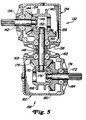
- FIGs 4 and 5 there is shown a second embodiment of the invention which in principle is quite similar to the embodiment of Figs 1 - 3. Specifically, shown is a forward end portion of an implement tongue 120 including a box beam 122 having an L-shaped hitch bracket 124 fixed to and depending from an undersurface thereof. The bottom of the bracket 124 is defined by a horizontal hitch plate 126 in which is incorporated a ball coupler 128.
- a power transmission assembly 130 is provided for driving apparatus (not shown) of the implement and includes a power shaft 131 mounted below and in parallel relationship to the box beam 122 by shaft support hangers (not shown).
- a first right angle gear box 132 including a housing 134 defined in part by removable rear and bottom shaft support walls 136 and 138, respectively, and an interior shaft support core 140.
- An output shaft 142 is rotatably supported in the rear wall 136 and core 140 by bearings 144 and 146, respectively, and is coupled to the power shaft 131 by a sprocket and chain type shaft coupler 147.
- a shaft 148 is rotatably supported in the bottom wall 138 and core 140 by bearings 150 and 152 respectively.
- a first set of meshed right angle bevel gears 154 and 156 are respectively mounted to the shafts 142 and 148.
- an identical second gear box 158 including a housing 160 defined in part by removable upper and front shaft support walls 162 and 164, respectively, and an interior shaft support core 166.
- the shaft 148 serves both as the input to the gear box 132 and as the output shaft of and as the sole support for the gear box 158 and is rotatably supported in the upper wall 162 and core 166 by bearings 168 and 170, respectively.
- An input shaft 172 is rotatably supported in the front wall 164 and core 166 by bearings 174 and 176, respectively, and is adapted for connection to the power take-off shaft of a towing tractor.
- a second set of meshed right angle bevel gears 178 and 180 are respectively mounted on the shaft 148 and the input shaft 172. It is noted that the shaft 148 is vertical and lies on an axis W which passes through the ball coupler 128.
- a hitch adapter 182 is provided for mounting the hitch bracket 124 of the tongue 120 to the three-point hitch of a towing tractor.
- the adapter 182 includes a horizontal U-shaped frame member 184 having opposite transversely spaced legs 186 joined to and projecting forwardly from a transverse portion 18 Hitch pins (only one shown) project outwardly from the forward end portions of the legs 186.
- a vertical, U-shaped support mast 190 has opposite transversely spaced legs 192 having lower ends fixed to the legs 186 of the frame member 184 and having upper ends joined by a cross member 194 carrying a bracket 196 supporting a cross pin 198.
- the two hitch pins 189 and cross pin 198 either cooperate for connection to three points of a quick coupler, like that described above, or may serve for direct coupling to the lower and upper links of the tractor three-point hitch.
- Fixed to a central bottom surface of the transverse portion 188 of the U-shaped frame member 184 is a horizontal hitch bar 200 carrying a vertical pin 202 received in the ball coupler 128 and held in place by a key or clip (not shown) inserted in a hole 204 provided in the pin.
- a steering or torque arm 206 is fixed to the bottom of and projects forwardly from the housing.
- the arm 206 has a downwardly projecting forward end 208 having a roller 210 mounted thereto for rotation about a horizontal axis and received for restrained up and down movement within a vertical guide track 212 fixed to a central vertical inner face of the transverse adapter portion 188.
- a downstop 214 like the previously described downstop 112, is fixed to and projects forwardly beyond one of the adapter legs 186 and has a downturned end 216 adapted for engaging a towing tractor drawbar for positioning the hitch adapter 182 for holding the implement tongue at a desired level for disposing the input shaft 172 of the gear box 158 at substantially the same height as the power take-off shaft of a towing tractor.
- gear boxes 132 and 158 share the shaft 148 which serves also as the sole support for the lower gear box 158.
- the steering arm 206 is fixed rather than pivoted to the lower gear box, carries a roller 210 rather than a ball with the roller 210 being received in a vertical guide track 212 rather than a horizontal track.
- the gear box 158 is mounted for pivoting about a vertical axis and that the arm 206 operates to transfer to the hitch adapter torque reaction forces tending to rotate the gear box about the axis W and operates in response to the pivotal movement of the hitch adapter 182 about the axis W, to pivot the gear box 158 about the axis W.
- the hitch adapter and transmission assembly of either embodiment are of relatively simple and inexpensive construction and cooperate to permit a towing tractor to turn sharply.
Landscapes
- Engineering & Computer Science (AREA)
- Mechanical Engineering (AREA)
- Life Sciences & Earth Sciences (AREA)
- Chemical & Material Sciences (AREA)
- Combustion & Propulsion (AREA)
- Transportation (AREA)
- Soil Sciences (AREA)
- Environmental Sciences (AREA)
- Agricultural Machines (AREA)
Claims (15)
Applications Claiming Priority (2)
| Application Number | Priority Date | Filing Date | Title |
|---|---|---|---|
| US92746786A | 1986-11-06 | 1986-11-06 | |
| US927467 | 1986-11-06 |
Publications (3)
| Publication Number | Publication Date |
|---|---|
| EP0269901A1 EP0269901A1 (de) | 1988-06-08 |
| EP0269901B1 true EP0269901B1 (de) | 1991-10-09 |
| EP0269901B2 EP0269901B2 (de) | 1995-06-07 |
Family
ID=25454775
Family Applications (1)
| Application Number | Title | Priority Date | Filing Date |
|---|---|---|---|
| EP87116265A Expired - Lifetime EP0269901B2 (de) | 1986-11-06 | 1987-11-05 | Gerät sowie Anschlussteil dafür |
Country Status (5)
| Country | Link |
|---|---|
| US (1) | US4738461A (de) |
| EP (1) | EP0269901B2 (de) |
| CA (1) | CA1279500C (de) |
| DE (1) | DE3773624D1 (de) |
| ES (1) | ES2025125T5 (de) |
Families Citing this family (68)
| Publication number | Priority date | Publication date | Assignee | Title |
|---|---|---|---|---|
| US4805927A (en) * | 1987-11-20 | 1989-02-21 | Deere & Company | Hitch adapter for use in connecting semi-integral, PTO-driven implements to tractor three-point hitch |
| US4776606A (en) * | 1987-11-20 | 1988-10-11 | Deere & Company | Hitch and drive structure for pto-driven, semi-integral implement |
| US4793430A (en) * | 1987-11-20 | 1988-12-27 | Deere & Company | Hitch and drive structure for PTO-driven, semi-integral implement |
| DE4000187A1 (de) * | 1990-01-05 | 1990-08-09 | Jakobi Wilhelm | Drehgetriebe fuer beliebige drehmomente |
| FR2667520A1 (fr) * | 1990-10-05 | 1992-04-10 | Guillaume Bernard | Presse plieuse a tablier articule par une charniere. |
| US5158500A (en) * | 1991-03-18 | 1992-10-27 | Ford New Holland, Inc. | Primary drive line and coupling for agricultural implements |
| DE4114280A1 (de) * | 1991-05-02 | 1992-11-05 | Deere & Co | Deichsel |
| US5152357A (en) * | 1991-05-31 | 1992-10-06 | Ford New Holland, Inc. | Swivel hitch for connecting an implement to a tractor |
| US5099937A (en) * | 1991-05-31 | 1992-03-31 | Ford New Holland, Inc. | Swivel hitch with reorientable lower gearbox |
| US5186271A (en) * | 1991-05-31 | 1993-02-16 | Ford New Holland, Inc. | Swivel hitch with improved mounting of lower gearbox |
| US5427192A (en) * | 1992-11-16 | 1995-06-27 | Deere & Company | Sliding pedestal shaft for PTO driven implements |
| US5355971A (en) * | 1993-07-28 | 1994-10-18 | Bush Hog Corporation | Drivetrain and load bearing swivel hitch assembly and combine incorporating same |
| FR2712764B1 (fr) * | 1993-11-23 | 1996-02-09 | Kuhn Sa | Machine agricole à timon perfectionné. |
| US5620054A (en) * | 1995-05-17 | 1997-04-15 | Dannar; Charles L. | Three point hitch for agriculture equipment |
| US5706901A (en) * | 1996-08-09 | 1998-01-13 | Deere & Company | Swivel hitch adaptable for use with either a tractor drawbar or two-point hitch |
| US6082085A (en) * | 1998-05-13 | 2000-07-04 | Agco Corporation | Foliage mowing implement having mechanical drive with main gearbox rotation |
| US6193259B1 (en) | 1999-01-28 | 2001-02-27 | Clarence B. Rupard | Mounting frame for use with three point hitch |
| US6412570B1 (en) | 2001-02-16 | 2002-07-02 | Agco Corporation | Draw bar swivel hitch |
| US7334645B2 (en) * | 2003-05-07 | 2008-02-26 | Degelman Industries Ltd. | Articulated power transfer apparatus |
| US20050167533A1 (en) * | 2004-01-05 | 2005-08-04 | Christy Jody M. | Apparatus for spreading particulate material from a work vehicle |
| US7213488B2 (en) * | 2004-01-14 | 2007-05-08 | Daniel Jeffrey K | Three way swivel divider gearbox for agricultural drive systems |
| US7055618B2 (en) | 2004-06-17 | 2006-06-06 | Cnh America Llc | Hydraulic pump drive |
| US7784812B1 (en) * | 2006-05-23 | 2010-08-31 | Francisco Javier Lares | Central multi directional transmission system |
| US7938206B2 (en) * | 2007-01-17 | 2011-05-10 | Deere & Company | Modular transmission assembly for an agricultural or industrial utility vehicle |
| US7654551B2 (en) * | 2007-02-02 | 2010-02-02 | Page James H | Skid steer attachment system |
| US7673570B1 (en) | 2008-12-01 | 2010-03-09 | Dawn Equipment Company | Row-clearing unit for agricultural implement |
| US8763713B2 (en) | 2012-01-27 | 2014-07-01 | Dawn Equipment Company | Agricultural implement with automatic down pressure control |
| US8985232B2 (en) | 2012-08-20 | 2015-03-24 | Dawn Equipment Company | Agricultural apparatus for sensing and providing feedback of soil property changes in real time |
| US9055712B2 (en) | 2010-09-15 | 2015-06-16 | Dawn Equipment Company | Agricultural apparatus with integrated controller for a row unit |
| US12389816B2 (en) | 2013-02-04 | 2025-08-19 | Deere & Company | Agricultural systems |
| US9226440B2 (en) | 2010-09-15 | 2016-01-05 | Dawn Equipment Company | Agricultural apparatus with hydraulic cylinder and manifold for a row unit |
| US9107337B2 (en) | 2012-08-20 | 2015-08-18 | Dawn Equipment Company | Agricultural apparatus for sensing and providing feedback of soil property changes in real time |
| US12171152B2 (en) | 2010-09-15 | 2024-12-24 | Deere & Company | System and method for adaptively controlling depth of ground-engaging planting row unit using forward sensor that measures residue ahead of row unit |
| US8544398B2 (en) | 2010-09-15 | 2013-10-01 | Dawn Equipment Company | Hydraulic down pressure control system for closing wheels of an agricultural implement |
| US9232687B2 (en) | 2010-09-15 | 2016-01-12 | Dawn Equipment Company | Agricultural systems |
| US8776702B2 (en) | 2010-09-15 | 2014-07-15 | Dawn Equipment Company | Hydraulic down pressure control system for an agricultural implement |
| US8544397B2 (en) | 2010-09-15 | 2013-10-01 | Dawn Equipment Company | Row unit for agricultural implement |
| US9107338B2 (en) | 2010-09-15 | 2015-08-18 | Dawn Equipment Company | Agricultural systems |
| US8863857B2 (en) | 2011-02-23 | 2014-10-21 | Dawn Equipment Company | Row unit for agricultural implement |
| US9271437B2 (en) | 2011-07-01 | 2016-03-01 | Charles H. Martin | Agricultural field preparation device |
| UA110988C2 (uk) | 2011-08-05 | 2016-03-10 | Пресіжн Плентінг Елелсі | Пристрій, системи і способи регулювання притискної сили рядного висівного апарата |
| US8636077B2 (en) | 2012-05-22 | 2014-01-28 | Dawn Equipment Company | Agricultural tool with structural housing for hydraulic actuator |
| CA3183433A1 (en) | 2012-07-25 | 2014-01-30 | Precision Planting Llc | Integrated implement downforce control systems, methods, and apparatus |
| US8910581B2 (en) | 2012-07-25 | 2014-12-16 | Dawn Equipment Company | Side dressing fertilizer coulter |
| US10104825B2 (en) * | 2012-09-06 | 2018-10-23 | Cnh Industrial America Llc | Pull frame for an agricultural implement |
| US9192091B2 (en) | 2013-02-01 | 2015-11-24 | Dawn Equipment Company | Agricultural apparatus with hybrid single-disk, double-disk coulter arrangement |
| US9215839B2 (en) | 2013-02-01 | 2015-12-22 | Dawn Equipment Company | Agricultural apparatus with hybrid single-disk, double-disk coulter arrangement |
| FR3013557B1 (fr) * | 2013-11-22 | 2016-01-01 | Kuhn Sa | Machine agricole, notamment machine pour la recolte de vegetaux, comportant deux unites de travail animees articulees a un meme bras lateral |
| US9668398B2 (en) | 2014-02-05 | 2017-06-06 | Dawn Equipment Company | Agricultural system for field preparation |
| US9241438B2 (en) | 2014-02-05 | 2016-01-26 | Dawn Equipment Company | Agricultural system for field preparation |
| US10721855B2 (en) | 2014-02-05 | 2020-07-28 | Dawn Equipment Company | Agricultural system for field preparation |
| US9615497B2 (en) | 2014-02-21 | 2017-04-11 | Dawn Equipment Company | Modular autonomous farm vehicle |
| CA2887974C (en) * | 2014-05-22 | 2016-12-06 | Agco Corporation | Swivel drawbar hitch mechanism for pull-type implement |
| US10582653B2 (en) | 2014-11-07 | 2020-03-10 | Dawn Equipment Company | Agricultural planting system with automatic depth control |
| US9848522B2 (en) | 2014-11-07 | 2017-12-26 | Dawn Equipment Company | Agricultural system |
| US11197411B2 (en) | 2014-11-07 | 2021-12-14 | Dawn Equipment Company | Agricultural planting system with automatic depth control |
| US9723778B2 (en) | 2014-11-07 | 2017-08-08 | Dawn Equipment Company | Agricultural system |
| US10444774B2 (en) | 2014-11-07 | 2019-10-15 | Dawn Equipment Company | Agricultural system |
| US10477760B2 (en) | 2015-12-28 | 2019-11-19 | Underground Agriculture, LLC | Agricultural organic device for weed control |
| US11083134B2 (en) | 2015-12-28 | 2021-08-10 | Underground Agriculture, LLC | Agricultural inter-row mowing device |
| US10980174B2 (en) | 2015-12-28 | 2021-04-20 | Underground Agriculture, LLC | Agricultural mowing device |
| US10645865B2 (en) | 2017-05-04 | 2020-05-12 | Dawn Equipment Company | Agricultural row unit with automatic control system for furrow closing device |
| US11006563B2 (en) | 2017-05-04 | 2021-05-18 | Dawn Equipment Company | Seed firming device for improving seed to soil contact in a planter furrow with feature designed to prevent the buildup of soil on the outer surfaces by discharging pressurized fluid |
| US10548260B2 (en) | 2017-05-04 | 2020-02-04 | Dawn Equipment Company | System for automatically setting the set point of a planter automatic down pressure control system with a seed furrow sidewall compaction measurement device |
| JP7102294B2 (ja) * | 2018-08-31 | 2022-07-19 | 株式会社クボタ | 作業機連結装置及び作業機連結方法 |
| US12207576B2 (en) * | 2020-03-02 | 2025-01-28 | Michael Fredrick Malone | Attachment for a towbar of a towable apparatus |
| KR102520899B1 (ko) * | 2020-12-30 | 2023-04-11 | 남기성 | 수평으로 길이가 조절되는 트랙터용 3점식 퀵히치 어댑터 |
| WO2025141908A1 (ja) * | 2023-12-27 | 2025-07-03 | 株式会社クボタ | 作業車両 |
Family Cites Families (13)
| Publication number | Priority date | Publication date | Assignee | Title |
|---|---|---|---|---|
| US3336996A (en) * | 1965-01-21 | 1967-08-22 | Massey Ferguson Inc | Combined draft and power transmission coupling |
| US3450220A (en) * | 1967-04-04 | 1969-06-17 | Jack W Frandsen | Automatic drawbar hitch |
| US3961677A (en) * | 1972-09-29 | 1976-06-08 | Jean Walterscheid Gmbh | Device for connecting a power transmission shaft of an agricultural implement, machine or the like to a tractor power take-off shaft |
| US3889977A (en) * | 1973-12-07 | 1975-06-17 | Suehiro Sharyo Seisakusho Kk | Trailers |
| US3862769A (en) * | 1973-12-26 | 1975-01-28 | Eaton Corp | Pivot construction |
| US3908398A (en) * | 1974-03-29 | 1975-09-30 | Gehl Co | Articulated vehicle assembly |
| US4027913A (en) * | 1975-12-08 | 1977-06-07 | J. I. Case Company | Frame structure for articulated vehicle |
| US4184558A (en) * | 1978-05-15 | 1980-01-22 | Deere & Company | Support for a PTO hookup assembly |
| NL7907546A (nl) * | 1979-10-11 | 1981-04-14 | Multinorm Bv | Vermogen-overbrengende koppelinrichting bij een trekker en daaraan gekoppeld werktuig. |
| FR2545315B1 (fr) * | 1983-05-03 | 1986-05-02 | Kuhn Sa | Machine agricole a dispositif de transmission de mouvement perfectionne |
| DE3411672A1 (de) * | 1984-03-29 | 1985-10-03 | Klöckner-Humboldt-Deutz AG Zweigniederlassung Fahr, 7702 Gottmadingen | Getriebe |
| FR2579405B1 (fr) * | 1985-03-28 | 1987-06-19 | Kuhn Sa | Machine agricole a dispositif de transmission perfectionne |
| US4640378A (en) * | 1985-08-22 | 1987-02-03 | Deere & Company | Power take-off system and isolation mounting therefor |
-
1987
- 1987-08-11 CA CA000544209A patent/CA1279500C/en not_active Expired - Lifetime
- 1987-08-19 US US07/088,501 patent/US4738461A/en not_active Expired - Lifetime
- 1987-11-05 ES ES87116265T patent/ES2025125T5/es not_active Expired - Lifetime
- 1987-11-05 DE DE8787116265T patent/DE3773624D1/de not_active Expired - Lifetime
- 1987-11-05 EP EP87116265A patent/EP0269901B2/de not_active Expired - Lifetime
Also Published As
| Publication number | Publication date |
|---|---|
| CA1279500C (en) | 1991-01-29 |
| EP0269901B2 (de) | 1995-06-07 |
| ES2025125B3 (es) | 1992-03-16 |
| ES2025125T5 (es) | 1995-09-16 |
| EP0269901A1 (de) | 1988-06-08 |
| DE3773624D1 (de) | 1991-11-14 |
| US4738461A (en) | 1988-04-19 |
Similar Documents
| Publication | Publication Date | Title |
|---|---|---|
| EP0269901B2 (de) | Gerät sowie Anschlussteil dafür | |
| US5706901A (en) | Swivel hitch adaptable for use with either a tractor drawbar or two-point hitch | |
| US4805927A (en) | Hitch adapter for use in connecting semi-integral, PTO-driven implements to tractor three-point hitch | |
| US3720047A (en) | Universal tractors | |
| CA1295869C (en) | Implement structure for facilitating easy mounting to and disconnection from a lawn and garden tractor | |
| US6860335B2 (en) | Front folding agricultural implement | |
| AU2008203430B2 (en) | Pin constructed for connecting a jack implement draft tongue and for supporting a PTO drive shaft assembly | |
| US5076042A (en) | Mowing machine | |
| US4662646A (en) | Trailing mower and drawbar articulation | |
| CA2225661C (en) | Implement swivel hitch for use with a quick-coupler | |
| US4102404A (en) | Articulated cultivator | |
| US4127283A (en) | Multiple drill hitch assembly | |
| EP0316899B1 (de) | Schlepper und durch den Schlepper gezogenes Gerät | |
| US3266817A (en) | Tractor coupling means | |
| US2259892A (en) | Tractor mounted corn picker and husker | |
| US5265403A (en) | Draft tongue for connecting PTO-driven implement to draft links of a towing vehicle | |
| US4398617A (en) | Rear axle-drawbar oscillation support system | |
| US3974880A (en) | Drawbar assembly | |
| KR20230068781A (ko) | 미드 모어 자동 연결 장치 | |
| EP4147550A1 (de) | Integrierte pto-welle und geräteträgeranordnung | |
| GB2213109A (en) | Improved trailer | |
| EP0507408B2 (de) | Landwirtschaftliche Maschine | |
| EP0551404B1 (de) | Fahrzeug mit rädern | |
| GB2128147A (en) | Agricultural tractor | |
| US12010936B2 (en) | Work vehicle |
Legal Events
| Date | Code | Title | Description |
|---|---|---|---|
| PUAI | Public reference made under article 153(3) epc to a published international application that has entered the european phase |
Free format text: ORIGINAL CODE: 0009012 |
|
| AK | Designated contracting states |
Kind code of ref document: A1 Designated state(s): DE ES FR GB IT NL |
|
| 17P | Request for examination filed |
Effective date: 19881019 |
|
| 17Q | First examination report despatched |
Effective date: 19900130 |
|
| ITF | It: translation for a ep patent filed | ||
| GRAA | (expected) grant |
Free format text: ORIGINAL CODE: 0009210 |
|
| AK | Designated contracting states |
Kind code of ref document: B1 Designated state(s): DE ES FR GB IT NL |
|
| REF | Corresponds to: |
Ref document number: 3773624 Country of ref document: DE Date of ref document: 19911114 |
|
| ET | Fr: translation filed | ||
| PLBI | Opposition filed |
Free format text: ORIGINAL CODE: 0009260 |
|
| 26 | Opposition filed |
Opponent name: CLAAS SAULGAU GMBH Effective date: 19920704 |
|
| NLR1 | Nl: opposition has been filed with the epo |
Opponent name: CLAAS SAULGAU GMBH |
|
| PLAB | Opposition data, opponent's data or that of the opponent's representative modified |
Free format text: ORIGINAL CODE: 0009299OPPO |
|
| R26 | Opposition filed (corrected) |
Opponent name: CLAAS SAULGAU GMBH Effective date: 19920704 |
|
| PUAH | Patent maintained in amended form |
Free format text: ORIGINAL CODE: 0009272 |
|
| STAA | Information on the status of an ep patent application or granted ep patent |
Free format text: STATUS: PATENT MAINTAINED AS AMENDED |
|
| 27A | Patent maintained in amended form |
Effective date: 19950607 |
|
| AK | Designated contracting states |
Kind code of ref document: B2 Designated state(s): DE ES FR GB IT NL |
|
| ITF | It: translation for a ep patent filed | ||
| ET3 | Fr: translation filed ** decision concerning opposition | ||
| NLR2 | Nl: decision of opposition | ||
| REG | Reference to a national code |
Ref country code: ES Ref legal event code: DC2A Kind code of ref document: T5 Effective date: 19950916 |
|
| NLR3 | Nl: receipt of modified translations in the netherlands language after an opposition procedure | ||
| REG | Reference to a national code |
Ref country code: GB Ref legal event code: IF02 |
|
| PGFP | Annual fee paid to national office [announced via postgrant information from national office to epo] |
Ref country code: GB Payment date: 20041027 Year of fee payment: 18 |
|
| PGFP | Annual fee paid to national office [announced via postgrant information from national office to epo] |
Ref country code: FR Payment date: 20041119 Year of fee payment: 18 |
|
| PGFP | Annual fee paid to national office [announced via postgrant information from national office to epo] |
Ref country code: DE Payment date: 20041130 Year of fee payment: 18 |
|
| PGFP | Annual fee paid to national office [announced via postgrant information from national office to epo] |
Ref country code: ES Payment date: 20041209 Year of fee payment: 18 |
|
| PGFP | Annual fee paid to national office [announced via postgrant information from national office to epo] |
Ref country code: NL Payment date: 20051016 Year of fee payment: 19 |
|
| PG25 | Lapsed in a contracting state [announced via postgrant information from national office to epo] |
Ref country code: IT Free format text: LAPSE BECAUSE OF NON-PAYMENT OF DUE FEES Effective date: 20051105 Ref country code: GB Free format text: LAPSE BECAUSE OF NON-PAYMENT OF DUE FEES Effective date: 20051105 |
|
| PG25 | Lapsed in a contracting state [announced via postgrant information from national office to epo] |
Ref country code: ES Free format text: LAPSE BECAUSE OF NON-PAYMENT OF DUE FEES Effective date: 20051107 |
|
| PG25 | Lapsed in a contracting state [announced via postgrant information from national office to epo] |
Ref country code: DE Free format text: LAPSE BECAUSE OF NON-PAYMENT OF DUE FEES Effective date: 20060601 |
|
| GBPC | Gb: european patent ceased through non-payment of renewal fee |
Effective date: 20051105 |
|
| PG25 | Lapsed in a contracting state [announced via postgrant information from national office to epo] |
Ref country code: FR Free format text: LAPSE BECAUSE OF NON-PAYMENT OF DUE FEES Effective date: 20060731 |
|
| REG | Reference to a national code |
Ref country code: FR Ref legal event code: ST Effective date: 20060731 |
|
| REG | Reference to a national code |
Ref country code: ES Ref legal event code: FD2A Effective date: 20051107 |
|
| PG25 | Lapsed in a contracting state [announced via postgrant information from national office to epo] |
Ref country code: NL Free format text: LAPSE BECAUSE OF NON-PAYMENT OF DUE FEES Effective date: 20070601 |
|
| NLV4 | Nl: lapsed or anulled due to non-payment of the annual fee |
Effective date: 20070601 |
|
| PLAB | Opposition data, opponent's data or that of the opponent's representative modified |
Free format text: ORIGINAL CODE: 0009299OPPO |