EP0270013A2 - Verfahren zum pneumatischen Einbringen dosierter Mengen pulverförmiger Stoffe in einen unter veränderlichem Druck stehenden Behälter - Google Patents
Verfahren zum pneumatischen Einbringen dosierter Mengen pulverförmiger Stoffe in einen unter veränderlichem Druck stehenden Behälter Download PDFInfo
- Publication number
- EP0270013A2 EP0270013A2 EP87117523A EP87117523A EP0270013A2 EP 0270013 A2 EP0270013 A2 EP 0270013A2 EP 87117523 A EP87117523 A EP 87117523A EP 87117523 A EP87117523 A EP 87117523A EP 0270013 A2 EP0270013 A2 EP 0270013A2
- Authority
- EP
- European Patent Office
- Prior art keywords
- pneumatic
- mixture
- injection
- adjustment
- pipes
- Prior art date
- Legal status (The legal status is an assumption and is not a legal conclusion. Google has not performed a legal analysis and makes no representation as to the accuracy of the status listed.)
- Withdrawn
Links
Images
Classifications
-
- C—CHEMISTRY; METALLURGY
- C21—METALLURGY OF IRON
- C21B—MANUFACTURE OF IRON OR STEEL
- C21B5/00—Making pig-iron in the blast furnace
- C21B5/001—Injecting additional fuel or reducing agents
- C21B5/003—Injection of pulverulent coal
-
- F—MECHANICAL ENGINEERING; LIGHTING; HEATING; WEAPONS; BLASTING
- F23—COMBUSTION APPARATUS; COMBUSTION PROCESSES
- F23K—FEEDING FUEL TO COMBUSTION APPARATUS
- F23K3/00—Feeding or distributing of lump or pulverulent fuel to combustion apparatus
- F23K3/02—Pneumatic feeding arrangements, i.e. by air blast
-
- F—MECHANICAL ENGINEERING; LIGHTING; HEATING; WEAPONS; BLASTING
- F23—COMBUSTION APPARATUS; COMBUSTION PROCESSES
- F23K—FEEDING FUEL TO COMBUSTION APPARATUS
- F23K3/00—Feeding or distributing of lump or pulverulent fuel to combustion apparatus
- F23K3/06—Feeding or distributing of lump or pulverulent fuel to combustion apparatus for shaft-type furnaces
Definitions
- the present invention relates to a pneumatic injection method, of metered quantities of pulverulent materials, at different places in an enclosure under variable pressure, according to which a pneumatic mixture is formed in a single metering device. comprising a relatively high content of pulverulent matter in propellant gas, this mixture is propelled through a common primary pipe to a dispensing head in which the mixture is split into secondary streams which are sent respectively to each of the points of injection through secondary lines.
- the powdered coal is released under pressure from a distribution hopper in a series of metering units in which the mixture of powdered coal and propellant gas is formed and from which the mixture thus formed is conveyed to the injection points in the shaft furnace.
- a metering device is generally used for each nozzle or for each pair of nozzles, so that the quantities injected through the nozzles can be metered individually.
- the metering devices used are of a type known per se, for example metering units with cellular rotors or metering units with slots as proposed in European patent application No. 0 126 917.
- These installations have the drawback that they require numerous relatively small pipes. long between the distribution hopper and the shaft furnace.
- dosing can be made difficult by the various variable parameters, in particular the pressure fluctuations inside the oven.
- a throttling section is also provided either in the secondary conduits or in the distribution head, where a pressure drop is created which is necessary for acceleration to the sonic speed of the pneumatic current.
- the acceleration of the pneumatic current to a sonic speed has the advantage that the flow conditions upstream from the place where the supercritical speed occurs are no longer influenced by flow conditions downstream from this place. This has, of course, the great advantage that one no longer has to take into account pressure fluctuations and other variable parameters existing in the enclosure into which the pulverulent materials are injected.
- they installed tions operating with concentrated current of the kind described above have the drawback that there is no longer any possibility of individual adjustment of the flow rate for each nozzle.
- the object of the present invention is to provide a new method of the type described in the preamble which combines the advantages of the two known methods.
- the invention proposes an injection process of the kind described in the preamble which is essentially characterized in that the flow rate of the pneumatic current is adjusted in each of the secondary pipes.
- This adjustment is preferably made at a section with variable throttling, in which the current is also accelerated to supercritical speed.
- the adjustment can be carried out manually or automatically under the control of flow detectors provided in each of the secondary pipes.
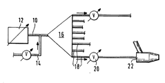
- a preferred embodiment will be described below, by way of example, with reference to the single figure which represents, very schematically, a pneumatic injection circuit of combustible materials in a shaft furnace.
- a metering device 12 which can be a metering device of the movable slot type, or a hopper with pneumatic or other metering, the pneumatic mixture consisting of powdered coal and propulsion and whose flow rate meets the demand for the quantity of coal per unit time from the shaft furnace.
- a pneumatic mixture with a high carbon concentration is formed which can, if necessary, be diluted by the addition of a variable quantity of inert gas injected through a line 14 upstream of the distributor.
- This pneumatic mixture is sent to a distribution head 16 of the type recommended by Luxembourg patent No 86.034.
- the primary pneumatic current is divided into secondary currents which are sent respectively through secondary conduits to each of the nozzles 22 of a blast furnace not shown.
- the number of secondary pipes 18 can for example correspond to the number of nozzles or half the number of nozzles.
- each of the secondary conduits 18 there is provided in each of the secondary conduits 18 a constriction 20 of variable section.
- This constriction is preferably carried out with a valve of the type recommended by the Luxembourg patent application No. 86.311, that is to say a valve whose passage is defined by the rotation of a movable sleeve inside a fixed socket, the two sockets being provided with openings and slots which can more or less overlap to define a more or less large passage.
- the acceleration of the secondary pneumatic currents is preferably carried out at the throttles 20.
- the method according to the present invention therefore has all the advantages of the sonic speed injection system, that is to say that the secondary pipes can be as short as possible, so as to reduce the space requirement around the oven.
- the metering conditions at the level of the metering device 12 are no longer affected by pressure fluctuations downstream of the throttles 20, in particular pressure fluctuations in the shaft furnace.
- the valves 20 can be adjusted manually, to take account of the operation of the oven.
- the flows passing through the various secondary conduits 18 are therefore established as a function of the openings at the throttles 20, while the total quantity of coal injected per unit of time is determined by the metering device 12.
- the function of the distributor 16 is therefore different from that of the distributor proposed by the Luxembourg patent application No 86.034. While in this one the distributor obviously had a distribution function, but also a uniform distribution, that is to say a distribution such that in each of the secondary conduits circulates the same flow of coal. On the other hand, in the method according to the present invention, the distributor 16 simply serves to divide the primary current into secondary currents whose flow rates are variable as a function of the variable sections of the throttles 20.
Landscapes
- Engineering & Computer Science (AREA)
- Chemical & Material Sciences (AREA)
- Combustion & Propulsion (AREA)
- Mechanical Engineering (AREA)
- General Engineering & Computer Science (AREA)
- Materials Engineering (AREA)
- Manufacturing & Machinery (AREA)
- Metallurgy (AREA)
- Organic Chemistry (AREA)
- Furnace Charging Or Discharging (AREA)
- Air Transport Of Granular Materials (AREA)
- Manufacture Of Iron (AREA)
- Blast Furnaces (AREA)
- Nozzles (AREA)
Applications Claiming Priority (2)
| Application Number | Priority Date | Filing Date | Title |
|---|---|---|---|
| LU86701A LU86701A1 (fr) | 1986-12-04 | 1986-12-04 | Procede d'injection par voie pneumatique,de quantites dosees de matieres pulverulentes,dans une enceinte se trouvant sous pression variable |
| LU86701 | 1986-12-04 |
Publications (2)
| Publication Number | Publication Date |
|---|---|
| EP0270013A2 true EP0270013A2 (de) | 1988-06-08 |
| EP0270013A3 EP0270013A3 (de) | 1989-04-26 |
Family
ID=19730834
Family Applications (1)
| Application Number | Title | Priority Date | Filing Date |
|---|---|---|---|
| EP87117523A Withdrawn EP0270013A3 (de) | 1986-12-04 | 1987-11-27 | Verfahren zum pneumatischen Einbringen dosierter Mengen pulverförmiger Stoffe in einen unter veränderlichem Druck stehenden Behälter |
Country Status (7)
| Country | Link |
|---|---|
| EP (1) | EP0270013A3 (de) |
| JP (1) | JP2900033B2 (de) |
| AU (1) | AU603162B2 (de) |
| BR (1) | BR8706640A (de) |
| CA (1) | CA1315991C (de) |
| LU (1) | LU86701A1 (de) |
| ZA (1) | ZA878817B (de) |
Cited By (4)
| Publication number | Priority date | Publication date | Assignee | Title |
|---|---|---|---|---|
| EP0340419A1 (de) * | 1988-04-21 | 1989-11-08 | Krupp Koppers GmbH | Vorrichtung für die Vergasung von feinkörnigen bis staubförmigen Brennstoffen |
| EP0383093A3 (de) * | 1989-02-14 | 1991-01-23 | Paul Wurth S.A. | Verfahren zum pneumatischen und dosierten Einblasen feinkörniger Feststoffe in einen unter veränderlichem Druck stehenden Behälter |
| WO2010081703A3 (de) * | 2009-01-15 | 2011-07-07 | Kurt Himmelfreundpointner | Verfahren und vorrichtung für das fördern von förderfähigen materialien |
| US8951315B2 (en) | 2008-11-12 | 2015-02-10 | Exxonmobil Research And Engineering Company | Method of injecting fuel into a gasifier via pressurization |
Families Citing this family (1)
| Publication number | Priority date | Publication date | Assignee | Title |
|---|---|---|---|---|
| LU90150B1 (de) * | 1997-10-15 | 1999-04-16 | Kuettner Gmbh & Co Kg Dr | Verfahren un Vorrichtung zum Einblasen von Reduktionsmittel in einen Schachtofen |
Family Cites Families (8)
| Publication number | Priority date | Publication date | Assignee | Title |
|---|---|---|---|---|
| DE3109111A1 (de) * | 1981-03-11 | 1982-09-23 | Fried. Krupp Gmbh, 4300 Essen | "anlage zum eingeben von kohle in metallurgische prozessgefaesse mit einer vielzahl von einblasstellen und verfahren zum betreiben der anlage" |
| JPS5869620A (ja) * | 1981-09-14 | 1983-04-25 | Nippon Steel Corp | 気送微粉炭分配装置 |
| LU84780A1 (fr) * | 1983-04-28 | 1984-11-28 | Wurth Paul Sa | Dispositif d'introduction de quantites dosees de matieres pulverulentes dans un fluide de propulsion pneumatique et application a un reservoir de distribution de matieres pulverulentes |
| FR2549580A1 (fr) * | 1983-07-19 | 1985-01-25 | Wurth Paul Sa | Procede et dispositif pour l'injection de charbon pulverise dans un four industriel |
| JPS6097121A (ja) * | 1983-11-02 | 1985-05-30 | Sumitomo Metal Ind Ltd | 粉粒体の流量分配制御方法 |
| LU86034A1 (fr) * | 1985-08-05 | 1987-03-06 | Wurth Paul Sa | Procede et dispositif d'injection,par voie pneumatique,de quantites dosees de matieres pulverulentes dans une enceinte se trouvant sous pression variable |
| DE3603078C1 (de) * | 1986-02-01 | 1987-10-22 | Kuettner Gmbh & Co Kg Dr | Verfahren und Vorrichtung zum dosierten Einfuehren feinkoerniger Feststoffe in einen Industrieofen,insbesondere Hochofen oder Kupolofen |
| LU86311A1 (de) * | 1986-02-19 |
-
1986
- 1986-12-04 LU LU86701A patent/LU86701A1/fr unknown
-
1987
- 1987-11-24 ZA ZA878817A patent/ZA878817B/xx unknown
- 1987-11-27 EP EP87117523A patent/EP0270013A3/de not_active Withdrawn
- 1987-11-27 CA CA000553028A patent/CA1315991C/en not_active Expired - Fee Related
- 1987-12-01 JP JP62304405A patent/JP2900033B2/ja not_active Expired - Lifetime
- 1987-12-03 BR BR8706640A patent/BR8706640A/pt not_active IP Right Cessation
- 1987-12-04 AU AU82088/87A patent/AU603162B2/en not_active Ceased
Cited By (6)
| Publication number | Priority date | Publication date | Assignee | Title |
|---|---|---|---|---|
| EP0340419A1 (de) * | 1988-04-21 | 1989-11-08 | Krupp Koppers GmbH | Vorrichtung für die Vergasung von feinkörnigen bis staubförmigen Brennstoffen |
| EP0383093A3 (de) * | 1989-02-14 | 1991-01-23 | Paul Wurth S.A. | Verfahren zum pneumatischen und dosierten Einblasen feinkörniger Feststoffe in einen unter veränderlichem Druck stehenden Behälter |
| US8951315B2 (en) | 2008-11-12 | 2015-02-10 | Exxonmobil Research And Engineering Company | Method of injecting fuel into a gasifier via pressurization |
| WO2010081703A3 (de) * | 2009-01-15 | 2011-07-07 | Kurt Himmelfreundpointner | Verfahren und vorrichtung für das fördern von förderfähigen materialien |
| EA021426B1 (ru) * | 2009-01-15 | 2015-06-30 | Курт Химмельфройндпойнтнер | Способ и устройство для транспортировки материалов, пригодных для транспортировки |
| US9074768B2 (en) | 2009-01-15 | 2015-07-07 | Kurt Himmelfreundpointner | Method and device for delivering deliverable materials |
Also Published As
| Publication number | Publication date |
|---|---|
| BR8706640A (pt) | 1988-07-19 |
| JP2900033B2 (ja) | 1999-06-02 |
| AU603162B2 (en) | 1990-11-08 |
| EP0270013A3 (de) | 1989-04-26 |
| JPS63147723A (ja) | 1988-06-20 |
| LU86701A1 (fr) | 1988-07-14 |
| ZA878817B (en) | 1988-08-31 |
| AU8208887A (en) | 1988-06-09 |
| CA1315991C (en) | 1993-04-13 |
Similar Documents
| Publication | Publication Date | Title |
|---|---|---|
| EP0383093B1 (de) | Verfahren zum pneumatischen und dosierten Einblasen feinkörniger Feststoffe in einen unter veränderlichem Druck stehenden Behälter | |
| BE1017673A3 (fr) | Procede et dispositif de projection de matiere pulverulente dans un gaz porteur. | |
| US6256975B1 (en) | Method for reliably removing liquid fuel from the fuel system of a gas turbine, and a device for carrying out the method | |
| FR2612606A1 (fr) | Procede et dispositif de destruction d'effluents gazeux toxiques | |
| EP0270013A2 (de) | Verfahren zum pneumatischen Einbringen dosierter Mengen pulverförmiger Stoffe in einen unter veränderlichem Druck stehenden Behälter | |
| FR2543675A1 (fr) | Distributeur de poudre, notamment pour pistolet de projection a chaud | |
| CA2204466A1 (en) | Apparatus and method for exposing product to a controlled environment | |
| FR2493963A1 (fr) | Procede et dispositif pour l'alimentation de plusieurs bruleurs d'une installation de chauffe en combustible granulaire ou pulverulent | |
| FR2724853A1 (fr) | Dispositif de distribution de solides pulverulents a la surface d'un substrat en vue d'y deposer un revetement | |
| EP0211295A1 (de) | Verfahren und Vorrichtung für ein dosiertes Einblasen auf pneumatischem Weg von feinkörnigen Feststoffen in einem unter wechselndem Druck stehenden Gehäuse | |
| FR2479709A1 (fr) | Procede et installation destines a engendrer un courant de vapeur | |
| CA2522932C (fr) | Procede de revetement par flamme et dispositif correspondant | |
| EP0168298A1 (de) | Zuführvorichtung mit gewichtsgeregelter Dosierung für staubförmiges Gut das einer pneumatischen Förderleitung zugeführt wird | |
| EP0022549B1 (de) | Verfahren und Anlage zum Einblasen fester Brennstoffe in einen Schachtofen | |
| FR2803022A1 (fr) | Procede d'installation d'alimentation en air d'un bruleur a combustible solide et pulverise | |
| GB2100145A (en) | Apparatus for detonation coating | |
| US2975002A (en) | Blow torch feeder control | |
| JPH0694564B2 (ja) | 高炉への粉体燃料吹込方法 | |
| EP0190592A1 (de) | Verfahren und Vorrichtung zum pneumatischen Einbringen dosierter Mengen pulverförmiger Stoffe in einem unter Druck stehenden Behälter und die Anwendung dieses Verfahrens auf Schachtöfen | |
| LU85920A1 (fr) | Dispositif de reglage du debit d'un liquide dans une conduite,notamment d'un liquide de refroidissement | |
| WO1993015362A1 (fr) | Procede et dispositif de substitution d'un premier flux de gaz accompagnant un flux de particules par un second flux de gaz | |
| US8623270B2 (en) | Dual outlet injection system | |
| EP0047026A2 (de) | Verfahren und Vorrichtung zum pneumatischen Spülen einer Drehachse, die pulverisierten Partikeln ausgesetzt ist | |
| DE3438950A1 (de) | Verfahren und vorrichtung zum aufteilen eines kohlestromes | |
| EP0044095A1 (de) | Verfahren und Vorrichtung zur uniformen pneumatischen Förderung feinkörniger Feststoffe und Anwendung zum Eintragen fester Brennstoffe in einen Schachtofen |
Legal Events
| Date | Code | Title | Description |
|---|---|---|---|
| PUAI | Public reference made under article 153(3) epc to a published international application that has entered the european phase |
Free format text: ORIGINAL CODE: 0009012 |
|
| AK | Designated contracting states |
Kind code of ref document: A2 Designated state(s): BE DE ES FR GB IT |
|
| 17P | Request for examination filed |
Effective date: 19881019 |
|
| PUAL | Search report despatched |
Free format text: ORIGINAL CODE: 0009013 |
|
| AK | Designated contracting states |
Kind code of ref document: A3 Designated state(s): BE DE ES FR GB IT |
|
| 17Q | First examination report despatched |
Effective date: 19900824 |
|
| STAA | Information on the status of an ep patent application or granted ep patent |
Free format text: STATUS: THE APPLICATION HAS BEEN WITHDRAWN |
|
| 18W | Application withdrawn |
Withdrawal date: 19911214 |