EP0270060A2 - Système de commande numérique pour des procédés à grande dynamique - Google Patents
Système de commande numérique pour des procédés à grande dynamique Download PDFInfo
- Publication number
- EP0270060A2 EP0270060A2 EP87117697A EP87117697A EP0270060A2 EP 0270060 A2 EP0270060 A2 EP 0270060A2 EP 87117697 A EP87117697 A EP 87117697A EP 87117697 A EP87117697 A EP 87117697A EP 0270060 A2 EP0270060 A2 EP 0270060A2
- Authority
- EP
- European Patent Office
- Prior art keywords
- path
- coarse
- interpolator
- elements
- control system
- Prior art date
- Legal status (The legal status is an assumption and is not a legal conclusion. Google has not performed a legal analysis and makes no representation as to the accuracy of the status listed.)
- Granted
Links
Images

Classifications
-
- G—PHYSICS
- G05—CONTROLLING; REGULATING
- G05B—CONTROL OR REGULATING SYSTEMS IN GENERAL; FUNCTIONAL ELEMENTS OF SUCH SYSTEMS; MONITORING OR TESTING ARRANGEMENTS FOR SUCH SYSTEMS OR ELEMENTS
- G05B19/00—Program-control systems
- G05B19/02—Program-control systems electric
- G05B19/18—Numerical control [NC], i.e. automatically operating machines, in particular machine tools, e.g. in a manufacturing environment, so as to execute positioning, movement or co-ordinated operations by means of program data in numerical form
- G05B19/41—Numerical control [NC], i.e. automatically operating machines, in particular machine tools, e.g. in a manufacturing environment, so as to execute positioning, movement or co-ordinated operations by means of program data in numerical form characterised by interpolation, e.g. the computation of intermediate points between programmed end points to define the path to be followed and the rate of travel along that path
- G05B19/4103—Digital interpolation
-
- G—PHYSICS
- G05—CONTROLLING; REGULATING
- G05B—CONTROL OR REGULATING SYSTEMS IN GENERAL; FUNCTIONAL ELEMENTS OF SUCH SYSTEMS; MONITORING OR TESTING ARRANGEMENTS FOR SUCH SYSTEMS OR ELEMENTS
- G05B2219/00—Program-control systems
- G05B2219/30—Nc systems
- G05B2219/34—Director, elements to supervisory
- G05B2219/34047—Dsp digital signal processor
-
- G—PHYSICS
- G05—CONTROLLING; REGULATING
- G05B—CONTROL OR REGULATING SYSTEMS IN GENERAL; FUNCTIONAL ELEMENTS OF SUCH SYSTEMS; MONITORING OR TESTING ARRANGEMENTS FOR SUCH SYSTEMS OR ELEMENTS
- G05B2219/00—Program-control systems
- G05B2219/30—Nc systems
- G05B2219/34—Director, elements to supervisory
- G05B2219/34101—Data compression, look ahead segment calculation, max segment lenght
-
- G—PHYSICS
- G05—CONTROLLING; REGULATING
- G05B—CONTROL OR REGULATING SYSTEMS IN GENERAL; FUNCTIONAL ELEMENTS OF SUCH SYSTEMS; MONITORING OR TESTING ARRANGEMENTS FOR SUCH SYSTEMS OR ELEMENTS
- G05B2219/00—Program-control systems
- G05B2219/30—Nc systems
- G05B2219/34—Director, elements to supervisory
- G05B2219/34167—Coarse fine, macro microinterpolation, preprocessor
-
- G—PHYSICS
- G05—CONTROLLING; REGULATING
- G05B—CONTROL OR REGULATING SYSTEMS IN GENERAL; FUNCTIONAL ELEMENTS OF SUCH SYSTEMS; MONITORING OR TESTING ARRANGEMENTS FOR SUCH SYSTEMS OR ELEMENTS
- G05B2219/00—Program-control systems
- G05B2219/30—Nc systems
- G05B2219/45—Nc applications
- G05B2219/45221—Edm, electrical discharge machining, electroerosion, ecm, chemical
Definitions
- the present invention relates to a numerical control system for highly dynamic processes according to the preamble of patent claim 1.
- a generic control system for highly dynamic processes is, for example, from the specialist book "R. Nann, computer control of production facilities", ISW 4 Springer- Verlag, Berlin, Heidelberg, New York, 1972, S 113-123, known.
- the coarse interpolator which is followed by a fine interpolator, operates in a predetermined time pattern.
- the use of this fixed time grid for the coarse interpolation has the disadvantage that a too small interpolation point distance is selected for weakly curved contours, as a result of which the coarse interpolator generates an unnecessary flood of data and is unnecessarily burdened with calculations of these interpolation points.
- the object of the present invention is to develop a numerical control system of the type mentioned at the outset in such a way that, despite the high accuracy of the path elements obtained by the coarse interpolator by coarse interpolation, a reduction in the amount of data to be handled by the coarse interpolator is achieved.
- the coarse interpolator according to the invention completely dispenses with the time grid basis generally regarded as necessary in the prior art and instead generates the path elements or interpolation points depending on the Contour of the web.
- the geometry-dependent data calculation considerably reduces the load on the coarse interpolator.
- Rounding errors and residual calculation errors are eliminated by checking the dimensional difference between the current base point and the end coordinate of the path or the end base of the path.
- Preferred predetermined vector lengths are the subject of claim 3.
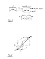
- the coarse interpolator 1 shows the two main components of the system: the coarse interpolator 1, which reduces the geometry to straight line sections and passes this reduced geometry together with further control information to the fine interpolator 2, and the fine interpolator 2, which in turn provides information about the system state, process state or geometry points reached to the coarse interpolator 1 can report back.
- the fine interpolator 2 contains a buffer 3, in which the information from the coarse interpolator 1 is stored in an orderly manner. This buffer 3 is normally populated with RAM (read and write memory with free access). The capacity of the memory can easily be up to one Mbyte, ie one million 8-bit data words.
- a smallest execution would have about 2 Kbytes and would be reloaded asynchronously by the coarse interpolator 1 in the case of long programs while the process was running - after confirmation. This process can of course also be carried out in blocks forwards and backwards, so that you can always interpolate back to the starting point.
- the fine interpolator 2 further contains an autonomous control system 4, which essentially consists of a sequence control.
- This sequence control is activated by various control signals and, depending on the status signals, executes one of several preprogrammed control sequences. These control sequences have the effect, for example, that the fine interpolator accepts a byte from the coarse interpolator 1, stores it at the address of the buffer 3 incremented by 1 and acknowledges the acceptance of the coarse interpolator 1. If the servowegraster clock signal T requests a new path increment, a control sequence for forward - depending on the servo direction signal R -. Backward interpolation activated.
- the running speed can be so high that the microseconds after the servo path clock signal T or even earlier the axis outputs RX, TX, RY, TY, RZ, TZ, RC, TC have the correct path increments. It is also possible to output process parameters S, K between two path increments; these can be stored in the buffer 3 at this point in the geometry, or can be output by the coarse interpolator 1 as a direct, manual command, which in turn triggers a corresponding control sequence.
- the process parameters S, K consist of an address S, which tells which parameter of the system or the process is to be changed, and a value K, which corresponds to the new setting of this parameter. In this way, all parameters can be controlled via a bus and an address decoder, which in the case of coincidence assumes the value K in a register, without great wiring effort.
- a vector of length L connects the point P1 with the point P2 in a straight line and, as will be explained below, does not deviate from the desired path anywhere more than an admissible path error E.
- This vector length L is subsequently the reference for the summation of the servowegraster clock signals, with which a vectorial speed fidelity of the system is guaranteed.
- the Cartesian axis components X, Y, Z and the component for the rotation C about the Z axis are also transferred to the fine interpolator and subsequently determine the division ratio in a programmable frequency divider 5.
- the number and type of axes can vary greatly from process to process.
- spark erosive wire cutting machines also have the conical axes U, V. Modern laser cutting machines also have at least five axes in order to always optimally align the laser beam with preformed sheet metal parts.
- a floating point processor with double precision accomplishes all basic operations and square roots in less than 8 ⁇ s, while e.g. a tangent function already requires 30 ⁇ s.
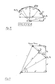
- 3 and 4 illustrate the principle of coarse interpolation without angular functions: a circular piece should be moved counterclockwise.
- the information is available, for example, according to DIN 66025 in ISO code, where GO3 means circular interpolation in the counterclockwise direction
- X ⁇ , Y ⁇ are the difference in mass between the start coordinates X S , Y S and the end coordinates X E , Y E.
- I ⁇ and Jiesslich are the difference in mass between the starting coordinates X S , Y S and the center of the circle M.
- the angle ⁇ is enclosed by the X axis and the connecting line circle center M - start coordinates X s , Y s .
- the angle ⁇ is enclosed by this connecting line and the perpendicular from the center M of the circle to the vector L 1.
- the vector L4 can be at most the same length as L1. If the table of permissible vector lengths L does not allow a direct jump, the vector L4 can be composed of two or more path elements L, X, Y. This final vector L4 can be used to compensate for various errors, such as the last rounding error, the finite calculation accuracy of the processor used and the often disruptive over-determination of the final coordinates X E , Y E by the ISO code.
- X ⁇ and Y ⁇ are in turn the difference in mass between the start coordinates X S , Y S and the end coordinates X E , Y E.
- Linear interpolation is a special case in that there are often geometry sets that only affect one axis. Due to the limited number of digits of the fine interpolator 2 (see also D. Binder, page 114), it makes sense to add a multiplication factor N to the path elements L, X, Y, Z, C, which determines how often a path element L, X, Y, Z, C to be executed in the fine interpolator 2. This leads to a further drastic reduction in the amount of data. It is assumed that in the X direction one has to interpolate 127,000 mm with a speed of only 10 mm / min and path increments of 1 ⁇ m.
- a traditional coarse interpolator would have a data flood of 38-100 path elements L, X, Y, Z, C generate, with the proposed principle, however, this can be done with a single path element set N * L, X, Y, Z, C, provided that the fine interpolator has 7 digits.
- the theoretically required linear path is designated by mit. It includes the pitch angle ⁇ with X ⁇ . So tangent ⁇ is Y ⁇ / X ⁇ , cosine ⁇ is X ⁇ / l, and sine ⁇ is Y ⁇ / l.
- Fig. 6 it is shown how the theoretical path l can be carried out with, for example, two sets of path elements L1, X1, Y1 and L2, X2, Y2, wherein the path error E is perpendicular to the theoretical path l.
- this value is equal to the vector length L divided by 128, 127.97 to 128.01 giving equally good results.
- This constant 128 can be determined experimentally or by computer simulation.
- the optimal value is that which gives the greatest number of permissible vector lengths L, which do not produce a final error due to rounding for any axis component combination X, Y, Z, C. If, for example, 80 path increments from coarse interpolator 1 have been calculated for the X axis, exactly 80 of them must be output later from fine interpolator 2 to axis output TX.
- each vector length L between 1 and 127 can be combined from a maximum of 2 sub-vectors.
Landscapes
- Engineering & Computer Science (AREA)
- Computing Systems (AREA)
- Theoretical Computer Science (AREA)
- Human Computer Interaction (AREA)
- Manufacturing & Machinery (AREA)
- Physics & Mathematics (AREA)
- General Physics & Mathematics (AREA)
- Automation & Control Theory (AREA)
- Complex Calculations (AREA)
- Numerical Control (AREA)
Applications Claiming Priority (4)
| Application Number | Priority Date | Filing Date | Title |
|---|---|---|---|
| DE3640987 | 1986-12-01 | ||
| DE3640987A DE3640987C1 (de) | 1986-12-01 | 1986-12-01 | Numerisches Steuersystem fuer hochdynamische Prozesse |
| DE3644952 | 1987-11-02 | ||
| DE3744952 | 1987-11-02 |
Publications (3)
| Publication Number | Publication Date |
|---|---|
| EP0270060A2 true EP0270060A2 (fr) | 1988-06-08 |
| EP0270060A3 EP0270060A3 (en) | 1990-01-31 |
| EP0270060B1 EP0270060B1 (fr) | 1994-03-30 |
Family
ID=25849905
Family Applications (1)
| Application Number | Title | Priority Date | Filing Date |
|---|---|---|---|
| EP87117697A Expired - Lifetime EP0270060B1 (fr) | 1986-12-01 | 1987-11-30 | Système de commande numérique pour des procédés à grande dynamique |
Country Status (2)
| Country | Link |
|---|---|
| EP (1) | EP0270060B1 (fr) |
| DE (1) | DE3789493D1 (fr) |
Cited By (2)
| Publication number | Priority date | Publication date | Assignee | Title |
|---|---|---|---|---|
| EP0567195B1 (fr) * | 1992-04-23 | 1997-10-22 | Dr. Johannes Heidenhain GmbH | Dispositif de commande numérique et procédé de commande du mouvement d'un outil |
| WO2003014848A1 (fr) * | 2001-08-11 | 2003-02-20 | Dr. Johannes Heidenhain Gmbh | Dispositif de production de grandeurs de reference pour des circuits de regulation d'une machine a commande numerique |
Families Citing this family (1)
| Publication number | Priority date | Publication date | Assignee | Title |
|---|---|---|---|---|
| CN105607577B (zh) * | 2014-11-20 | 2018-07-13 | 沈阳高精数控智能技术股份有限公司 | 一种基于轴向精度的小线段过渡方法 |
Family Cites Families (4)
| Publication number | Priority date | Publication date | Assignee | Title |
|---|---|---|---|---|
| GB1319286A (en) * | 1969-06-21 | 1973-06-06 | Olivetti & Co Spa | Numerical control device |
| DE2049898A1 (de) * | 1969-10-13 | 1971-04-22 | Gen Electric | Numerische Regeleinrichtung fur eine Werkzeugmaschine |
| DE2323684A1 (de) * | 1972-05-16 | 1973-11-29 | Hughes Aircraft Co | Vorrichtung zur erzeugung von steuersignalen fuer bewegungen in zueinander senkrechten richtungen |
| DE2845953A1 (de) * | 1977-11-10 | 1979-05-17 | Numerik Karl Marx Veb | Steuereinrichtung zum numerischen steuern eines werkzeuges |
-
1987
- 1987-11-30 DE DE87117697T patent/DE3789493D1/de not_active Expired - Lifetime
- 1987-11-30 EP EP87117697A patent/EP0270060B1/fr not_active Expired - Lifetime
Cited By (3)
| Publication number | Priority date | Publication date | Assignee | Title |
|---|---|---|---|---|
| EP0567195B1 (fr) * | 1992-04-23 | 1997-10-22 | Dr. Johannes Heidenhain GmbH | Dispositif de commande numérique et procédé de commande du mouvement d'un outil |
| WO2003014848A1 (fr) * | 2001-08-11 | 2003-02-20 | Dr. Johannes Heidenhain Gmbh | Dispositif de production de grandeurs de reference pour des circuits de regulation d'une machine a commande numerique |
| US6772020B2 (en) | 2001-08-11 | 2004-08-03 | Johannes Heidenhain Gmbh | Arrangement for generating command variables for control loops of a numerically controlled machine |
Also Published As
| Publication number | Publication date |
|---|---|
| DE3789493D1 (de) | 1994-05-05 |
| EP0270060B1 (fr) | 1994-03-30 |
| EP0270060A3 (en) | 1990-01-31 |
Similar Documents
| Publication | Publication Date | Title |
|---|---|---|
| EP0270059B1 (fr) | Système de commande numérique pour des procédés à grande dynamique | |
| DE69711812T2 (de) | Drei-dimensionales Bearbeitungsverfahren und Aufzeichnungsmedium mit gespeichertem Programm für drei-dimensionale Berabeitungssteuerung | |
| DE2636148C2 (de) | Verfahren zur Bahnsteuerung eines Elementes mittels linearer oder zirkularer Interpolation | |
| DE3587732T2 (de) | Verfahren zum Vorbereiten von numerischen Steuerungsdaten für das Einsetzen von Bauelementen. | |
| DE3786014T2 (de) | Verfahren zur entwicklung von ns-part-programmen fuer maschinelle laserbearbeitung. | |
| DE2422102A1 (de) | Numerische steuerung zur erzeugung einer parabolischen auskehlung | |
| DE4107707A1 (de) | Verfahren und vorrichtung zum kompensieren von lagefehlern | |
| DE3238360C2 (fr) | ||
| DE3234946A1 (de) | Verfahren und vorrichtung zur bearbeitung eines dreidimensionalen profils in einem werkstueck | |
| DE112012006403T5 (de) | Numerik-Steuervorrichtung | |
| DE3545795A1 (de) | Verfahren und vorrichtung fuer die numerische steuerung mit geschwindigkeitsdifferenz-verminderung | |
| EP0477397B2 (fr) | Procédé pour déterminer le contour de trajectoire de l'outil pour machines à commande numérique | |
| DE102022101000B4 (de) | Verfahren und Vorrichtung zum Erzeugen einer CAM-orientierten Zeit-Spline-Kurve und -Oberfläche | |
| DE3688187T2 (de) | Verfahren zur bearbeitung eines gebietes. | |
| DE2338880A1 (de) | Verfahren und vorrichtungen zur steuerung der beweglichen teile einer werkzeugmaschine durch ein numerisches umriss- oder punkt-fuer-punkt-steuerungssystem, wobei zwei teile der maschine unabhaengig voneinander entlang einer gemeinsamen achse bewegt werden koennen | |
| DE2632278C2 (de) | Verfahren zur Interpolation der Bahn eines bewegbaren Teils einer numerisch gesteuerten Maschine | |
| DE2103049C3 (de) | Vorrichtung eines numerisch gesteuerten Folgesystems | |
| EP0270060B1 (fr) | Système de commande numérique pour des procédés à grande dynamique | |
| EP0561813B1 (fr) | Procede pour la determination de parametres de commande pilote pour une regulation de position | |
| DE3644952A1 (de) | Numerisches steuersystem fuer hochdynamische prozesse | |
| DE69323795T2 (de) | Numerische Steuerungsvorrichtung zur Werkzeugführung entlang nicht-orthogonaler mechanischer Achsen | |
| DE112021002766T5 (de) | Bearbeitungspfaderstellungsvorrichtung | |
| DE112021001856T5 (de) | Steuerung, Steuersystem und Steuerverfahren für eine Werkzeugmaschine | |
| DE68928749T2 (de) | Verfahren zur evolventen-interpolation | |
| DE3883521T2 (de) | Regelverfahren der laserenergie. |
Legal Events
| Date | Code | Title | Description |
|---|---|---|---|
| PUAI | Public reference made under article 153(3) epc to a published international application that has entered the european phase |
Free format text: ORIGINAL CODE: 0009012 |
|
| AK | Designated contracting states |
Kind code of ref document: A2 Designated state(s): CH DE FR GB IT LI LU SE |
|
| PUAL | Search report despatched |
Free format text: ORIGINAL CODE: 0009013 |
|
| AK | Designated contracting states |
Kind code of ref document: A3 Designated state(s): CH DE FR GB IT LI LU SE |
|
| 17P | Request for examination filed |
Effective date: 19900116 |
|
| 17Q | First examination report despatched |
Effective date: 19911224 |
|
| GRAA | (expected) grant |
Free format text: ORIGINAL CODE: 0009210 |
|
| AK | Designated contracting states |
Kind code of ref document: B1 Designated state(s): CH DE FR GB IT LI LU SE |
|
| PG25 | Lapsed in a contracting state [announced via postgrant information from national office to epo] |
Ref country code: SE Free format text: THE PATENT HAS BEEN ANNULLED BY A DECISION OF A NATIONAL AUTHORITY Effective date: 19940330 |
|
| REF | Corresponds to: |
Ref document number: 3789493 Country of ref document: DE Date of ref document: 19940505 |
|
| ITF | It: translation for a ep patent filed | ||
| ET | Fr: translation filed | ||
| GBT | Gb: translation of ep patent filed (gb section 77(6)(a)/1977) |
Effective date: 19940706 |
|
| PG25 | Lapsed in a contracting state [announced via postgrant information from national office to epo] |
Ref country code: LU Free format text: LAPSE BECAUSE OF NON-PAYMENT OF DUE FEES Effective date: 19941130 |
|
| PLBE | No opposition filed within time limit |
Free format text: ORIGINAL CODE: 0009261 |
|
| STAA | Information on the status of an ep patent application or granted ep patent |
Free format text: STATUS: NO OPPOSITION FILED WITHIN TIME LIMIT |
|
| 26N | No opposition filed | ||
| REG | Reference to a national code |
Ref country code: GB Ref legal event code: IF02 |
|
| PGFP | Annual fee paid to national office [announced via postgrant information from national office to epo] |
Ref country code: CH Payment date: 20061114 Year of fee payment: 20 |
|
| PGFP | Annual fee paid to national office [announced via postgrant information from national office to epo] |
Ref country code: DE Payment date: 20061124 Year of fee payment: 20 Ref country code: FR Payment date: 20061124 Year of fee payment: 20 |
|
| PGFP | Annual fee paid to national office [announced via postgrant information from national office to epo] |
Ref country code: GB Payment date: 20061127 Year of fee payment: 20 |
|
| PGFP | Annual fee paid to national office [announced via postgrant information from national office to epo] |
Ref country code: IT Payment date: 20061130 Year of fee payment: 20 |
|
| REG | Reference to a national code |
Ref country code: GB Ref legal event code: PE20 |
|
| REG | Reference to a national code |
Ref country code: CH Ref legal event code: PL |
|
| PG25 | Lapsed in a contracting state [announced via postgrant information from national office to epo] |
Ref country code: GB Free format text: LAPSE BECAUSE OF EXPIRATION OF PROTECTION Effective date: 20071129 |