EP0270112A2 - Funksenderempfängersystem zur Erhöhung oder zur Verringerung der Übertragungskanäle - Google Patents
Funksenderempfängersystem zur Erhöhung oder zur Verringerung der Übertragungskanäle Download PDFInfo
- Publication number
- EP0270112A2 EP0270112A2 EP87117896A EP87117896A EP0270112A2 EP 0270112 A2 EP0270112 A2 EP 0270112A2 EP 87117896 A EP87117896 A EP 87117896A EP 87117896 A EP87117896 A EP 87117896A EP 0270112 A2 EP0270112 A2 EP 0270112A2
- Authority
- EP
- European Patent Office
- Prior art keywords
- portions
- output
- frequency
- transmitter
- receiver
- Prior art date
- Legal status (The legal status is an assumption and is not a legal conclusion. Google has not performed a legal analysis and makes no representation as to the accuracy of the status listed.)
- Granted
Links
Images


Classifications
-
- H—ELECTRICITY
- H04—ELECTRIC COMMUNICATION TECHNIQUE
- H04B—TRANSMISSION
- H04B1/00—Details of transmission systems, not covered by a single one of groups H04B3/00 - H04B13/00; Details of transmission systems not characterised by the medium used for transmission
- H04B1/74—Details of transmission systems, not covered by a single one of groups H04B3/00 - H04B13/00; Details of transmission systems not characterised by the medium used for transmission for increasing reliability, e.g. using redundant or spare channels or apparatus
Definitions
- the present invention relates to a radio transmitter-receiver system for increasing or decreasing communication channels, more particularly to a radio transmitter-receiver system for increasing or decreasing communication channels by varying a frequency of an IF local oscillator in a heterodyne type radio transmitter-receiver instead of using a duplexer for an RF signal.
- the communication network is constituted of lines provided among many node stations, and back-up lines are provided between each station, for example, when lines are provided between stations A, B, C, and D, if there is a breakdown in the line between stations A and D, communication between the stations A and D is established through a line between stations A and C and a line between stations C and D.
- a different frequency is usually applied to each line, and each line has a transmission capacity of, for example, 1200 channels per one frequency.
- a standby radio transmitter-receiver is usually provided, to continue communications in the event of a malfunction of the working radio transmitter-receiver, and thus a station generally comprises both a working and a standby radio transmitter-receiver.
- a line failure occurs, such as a deterioration in transmission characteristics caused by heavy rain, an obstruction by microwave shielding matter, damage to an antenna, or the like, communication by even a normal radio transmitter-receiver becomes difficult or impossible.
- the channel capacity of the back-up line is provided with a sufficient margin, the failed line can be by-passed and eventually replaced.
- the margin is insufficient, a back-up can be provided for only a short time, but the replacement of the failed line may take a long time, and thus there is a drop in capacity in the intervening period.
- the present invention is intended to solve these problems by changing the constitution of the radio transmitter-receiver, and thus make it possible to increase or decrease the number of channels in the line.
- An object of the present invention is to provide a radio transmitter-receiver system for increasing or decreasing communication channels, wherein the communication channels are increased or decreased at a low cost by changing the constitution of the conventional radio transmitter-receiver, thus avoiding the necessity for providing a plurality of high cost branching circuits.
- Another object of the present invention is to provide a radio transmitter-receiver system for increasing or decreasing communication channels wherein, by providing a multiplexer and a divider at an entrance and an exit of the radio frequency portions, respectively, instead of using branching circuits, an increase of a loss of transmission power and a deterioration of the noise figure upon reception are prevented, and a reduction of space occupied becomes possible because the number of branching circuits used is reduced.
- a further object of the present invention is to provide a radio transmitter-receiver system for increasing or decreasing communication channels, wherein the frequency applied at the lines can be changed comparatively easily by changing a quartz oscillator or changing the parts rating in a synthesizer type radio transmitter-receiver.
- a radio transmitter-receiver system for increasing or decreasing communication channels, comprising a plurality of antennas, a plurality of transmitter-receivers, a plurality of IF (intermediate frequency) multiplexers, a plurality of IF dividers, and a plurality of communication lines between the antennas.
- the antennas receive input RF signals and transmit output RF signals.
- Each of the plurality of transmitter-receivers has an RF portion and an IF portion. The RF portion receives an RF signal from the antenna and supplies an RF output to the antenna.
- An intermediate frequency from the IF portions and a radio frequency from the antennas at the RF portions are converted to a radio frequency to the antennas and to an intermediate frequency to the IF portions, respectively.
- a baseband input and an intermediate frequency from the RF portions at the IF portions are converted to an intermediate frequency to the RF portions and to a baseband output, respectively.
- the IF portion is provided with local oscillators generating a variable frequency.
- An IF multiplexer and an IF divider are located between the RF portion and the IF portion.
- the IF multiplexer receives outputs from a plurality of IF portions and supplies an output to the RF portion.
- the IF divider receives an output from the RF portion and supplies outputs to a plurality of IF portions. Each communication line between the antennas is allotted a different frequency, to form a communication network.
- a radio transmitter-receiver system comprises, for example, node stations A, B, C, and D, and communication lines provided therebetween.
- the lines are provided with a frequency division system and are allotted different frequencies.
- the line between the node stations A and D is allotted the frequency f1
- the line between the node stations A and C is allotted the frequency f2
- the line between the node stations A and B is allotted the frequency f3
- the transmission capacity for one frequency is, for example, 1200 channels.
- each frequency band comprises three frequencies, f 1-1 to f 1-3 , f 2-1 to f 2-3 , or the like, and thus the capacity for one frequency band becomes 1200 ⁇ 3 channels.
- each station comprises at least two radio transmitter-receivers.
- the pairs of reference numerals 11 and 11A, 12 and 12A, and 13 and 13A each represent one radio transmitter-receiver apparatus, respectively.
- the radio transmitter-receiver 11 and 11A is allotted the frequency f 1-1
- the radio transmitter-receiver 12 and 12A is allotted the frequency f 1-2
- the radio transmitter-receiver 13 and 13A is allotted the frequency f 1-3 .
- the node station A is provided with three radio transmitter-receivers for each of the frequency f1 , the frequency f2 , and the frequency f3.
- the above arrangement is also provided in the node stations B, C, or the like.
- both transmitting and receiving signals pass through a duplexer 201 connected to an antenna (ANT).
- the receiving signals are branched by branching circuits 203 to pairs of working and standby transmitter-receivers (11, 11A; 12, 12A; 13, 13A) through RF dividers (H) 15, 17, 19, respectively.
- the transmitting signals from the transmitter-receivers 11 and 11A, 12 and 12A, and 13 and 13A are selected by RF switches (SW) 14, 16, 18, respectively.
- the selected signals from the transmitter-receivers 11, 11A; 12, 12A; and 13, 13A are multiplexed by branching circuits 202 and transmitted to the antenna through the duplexer 201.
- an upper part shows a transmitter portion which receives a baseband input.
- the baseband input passes through a low-pass filter 21, an amplifier 22, a modulator (MOD) 23, a mixer 24, which mixes an output from an intermediate frequency oscillator 25 and the output of the modulator 23, a band-pass filter 26, an amplifier 27, a mixer 28, which mixes an output from a radio frequency oscillator 29 and the output of the amplifier 27, a band-pass filter 30, and an amplifier 31.
- the RF output is output from the amplifier 31.
- a lower part shows a receiver which receives an RF input.
- the RF input passes through a mixer 41, which mixes the RF input and an output of an RF oscillator 42, a band-pass filter 43, an amplifier 44, a mixer 45, which mixes an output of an intermediate frequency oscillator 46 and the output of the amplifier 44, a band-pass filter 47, an amplifier 48, a demodulator (DEM) 49, a low-pass filter 50, and an amplifier 51.
- the baseband output is output from the amplifier 51.
- Fig. 5 The constitution of a group of radio transmitter-receivers in a radio transmitter-receiver system for increasing or decreasing communication channels according to an embodiment of the present invention is shown in Fig. 5.
- the node station comprises a plurality of groups of radio transmitter-receivers; and, the radio transmitter-receiver system comprises a plurality of the node stations and communication lines provided therebetween.
- Each group comprises an antenna 61, a duplexer 62, an RF switch 63, an RF divider 64, two radio transmitter-receivers, and an IF portion (#n) 69 of another transmitter-receiver.
- the two radio transmitter- receivers are a working apparatus (#1) and a standby apparatus (#2).
- Each transmitter-receiver comprises an RF portion and an IF portion, and further, is divided into a transmitter portion and a receiver portion.
- the antenna 61 is connected to a duplexer 62, for example, a circulator, and the duplexer 62 is connected to the RF switch (SW) 63 and the RF divider (H) 64.
- the RF portion (RF1) 65 of the working transmitter-receiver supplies an output to the switch 63 and receives a signal from the divider 64.
- the RF portion (RF2) 66 of the standby transmitter-receiver supplies an output to the switch 63 and receives a signal from the divider 64.
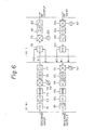
- the transmitter portion and the receiver portion are shown at the upper and lower parts of Fig. 6, respectively.
- the transmitter portion comprises a low-pass filter 71, an amplifier 72, a modulator (MOD) 73, an IF mixer 74, which mixes the outputs of the modulator 73 and an IF variable frequency oscillator 75, a band-pass filter 76, an amplifier 77, an IF multiplexer (H1) 78, an RF mixer 79, which mixes the output of the divider 78 and an output of an RF local oscillator 80, a band-pass filter 81, and an amplifier 82.
- a baseband input is applied to the low-pass filter 71 and passes through the above-mentioned elements in the above sequence, and an RF output is output from the amplifier 82.
- the receiver portion comprises an RF mixer 86, which mixes the RF input and an output from an RF local oscillator 87, a band-pass filter 88, an amplifier 89, an IF divider (H2) 90, an IF mixer 91, which mixes the output of the divider 90 and an output from an IF variable frequency oscillator 92, a band-pass filter 93, an amplifier 94, a demodulator (DEM) 95, a low-pass filter 96, and an amplifier 97.
- the RF input is applied to the mixer 86 and passes through the above-mentioned elements in the above sequence, and a baseband output is output from the amplifier 97.
- a multiplexer (H1) and a divider (H2) are inserted at point c and point d of Fig. 4, respectively, and the intermediate frequency oscillators 25 and 46 of Fig. 4 are replaced by the IF variable frequency oscillators 75 and 92, respectively.
- the RF1 (65) and IF #1 (67) correspond to the transmitter-receiver 11
- the RF2 (66) and IF #2 (68) correspond to the transmitter-receiver 11A, of Fig. 3.
- the transmitter-receivers 12, 12A and 13, 13A can be replaced with corresponding groups as shown in Fig. 5.
- the above-mentioned transmitter-receivers are provided for each of the frequencies f1 , f2 , f3 , and the like.
- Each RF portion can be connected to three IF portions (#1, #2, #n), as shown in Fig. 6, since the operating frequency at the RF portion (GHz) is much higher than that of the IF portion (MHz) and a bandwidth of the RF portion is wider than that of the IF portion. Therefore, the RF portion has a plurality of channels, and thus more than three IF portions can be connected to one RF portion.
- IF #n may be included in any group.
- the multiplexer 78 is supplied with outputs from the IF portions #1, #2, and #n, and the divider 90 supplies an output to the IF portions #1, #2, and #n.
- RF1 (65) is connected to the IF #1 (67) and the RF2 (66) is connected to the IF #2 (68). There is no RF portion corresponding to the IF #n (69).
- the band limitation of each channel is usually carried out in the IF band or the baseband.
- the following countermeasures can be taken. For example, if there is a failure of the communication line between stations A and D, the transmission frequency f1 in the A station (f 1-1 to f 1-3 hereinafter) is changed to the frequencies f2 and f3. This change is made by changing the frequency of the IF variable frequency oscillator in the IF portion. The frequency-changed signal is then applied to the communication lines between the stations A and C and between the stations A and B, by connecting the IF #n (69) to the RF1 (65).
- the IF #n (69) is a working IF portion in a group using the frequency f1 before the failure, and the RF1 (65) belongs to a group using the frequency f2 or f3.
- the IF #n (69) may be connected to the RF2 (66).
- the IF #1 (67) is the working apparatus and the IF #2 (68) is the standby apparatus, i.e., the RF1 (65) is in an operational state and the RF2 (66) is in a non-operational state, and thus the IF #n (69) is connected to the RF1 (65).
- the IF #n (69) is utilized only for the operational apparatus, and not used for the standby apparatus.
- the frequency f1 of the radio transmitter-receivers is changed to the frequencies f4 and f5 , and the frequency-changed signals are then applied to the communication lines between the stations D and B and between the stations D and C.
- the standby IF portions are brought to the operational state to deal with the increased amount of communication data from the stations A and D.
- communication between the stations A and D can be continued over a long period via the routes A ⁇ C ⁇ D and A ⁇ B ⁇ D.
- the frequency f1 on a failed line may be used on a by-passed line.
- the frequencies of the RF local oscillators in each group are the same, the IF local oscillator of the IF #n does not need to change the frequency in the stations A and D, but this frequency change is necessary in the stations B and C. If, in each group, the frequency of the RF local oscillator is different, the frequency of the IF local oscillator of the IF #n must be changed to obtain the frequency f1 , even in the stations A and D.
- the frequency f1 of the standby radio transmitter-receiver at a station is changed to the frequency f2 for operational use, and thus any sudden failure in communications can be overcome.
Landscapes
- Engineering & Computer Science (AREA)
- Computer Networks & Wireless Communication (AREA)
- Signal Processing (AREA)
- Transceivers (AREA)
- Transmitters (AREA)
- Mobile Radio Communication Systems (AREA)
Applications Claiming Priority (2)
| Application Number | Priority Date | Filing Date | Title |
|---|---|---|---|
| JP288532/86 | 1986-12-03 | ||
| JP61288532A JPS63141417A (ja) | 1986-12-03 | 1986-12-03 | 無線送受信装置のチャンネル増減方式 |
Publications (3)
| Publication Number | Publication Date |
|---|---|
| EP0270112A2 true EP0270112A2 (de) | 1988-06-08 |
| EP0270112A3 EP0270112A3 (en) | 1989-07-05 |
| EP0270112B1 EP0270112B1 (de) | 1993-03-10 |
Family
ID=17731457
Family Applications (1)
| Application Number | Title | Priority Date | Filing Date |
|---|---|---|---|
| EP87117896A Expired - Lifetime EP0270112B1 (de) | 1986-12-03 | 1987-12-03 | Funksenderempfängersystem zur Erhöhung oder zur Verringerung der Übertragungskanäle |
Country Status (5)
| Country | Link |
|---|---|
| US (1) | US4965852A (de) |
| EP (1) | EP0270112B1 (de) |
| JP (1) | JPS63141417A (de) |
| CA (1) | CA1263148A (de) |
| DE (1) | DE3784643T2 (de) |
Cited By (1)
| Publication number | Priority date | Publication date | Assignee | Title |
|---|---|---|---|---|
| WO1996010871A1 (en) * | 1994-09-30 | 1996-04-11 | Qualcomm Incorporated | Multiple band radio |
Families Citing this family (8)
| Publication number | Priority date | Publication date | Assignee | Title |
|---|---|---|---|---|
| DE19612108A1 (de) * | 1996-03-27 | 1997-10-02 | Bosch Gmbh Robert | Punkt-zu-Mehrpunkt Funkübertragungssystem |
| FI100286B (fi) * | 1996-04-01 | 1997-10-31 | Nokia Mobile Phones Ltd | Lähetin/vastaanotin RF-signaalin lähettämiseksi ja vastaanottamiseksi kahdella taajuusalueella |
| FI104134B1 (fi) * | 1997-07-31 | 1999-11-15 | Nokia Networks Oy | Datan- ja virransyötön toteuttava kaapeliliitäntä |
| GB9804708D0 (en) * | 1998-03-05 | 1998-04-29 | Nec Technologies Uk Ltd | Radio transmitter/reciever channel selection |
| JP3608936B2 (ja) * | 1998-03-20 | 2005-01-12 | 富士通株式会社 | 多重無線送信装置,多重無線受信装置,多重無線送受信装置及び多重無線送受信システム |
| JP3796372B2 (ja) * | 1999-06-07 | 2006-07-12 | シャープ株式会社 | ミリ波帯通信装置 |
| US6766482B1 (en) | 2001-10-31 | 2004-07-20 | Extreme Networks | Ethernet automatic protection switching |
| US20050152316A1 (en) * | 2004-01-08 | 2005-07-14 | Chien-Hsing Liao | CDMA transmitting and receiving apparatus with multiple applied interface functions and a method thereof |
Family Cites Families (7)
| Publication number | Priority date | Publication date | Assignee | Title |
|---|---|---|---|---|
| NL235664A (de) * | 1958-01-31 | |||
| US3549811A (en) * | 1969-10-07 | 1970-12-22 | Einar Borresen | Radio transmission system |
| US4039947A (en) * | 1976-06-29 | 1977-08-02 | Bell Telephone Laboratories, Incorporated | Protection switching system for microwave radio |
| FR2363244A1 (fr) * | 1976-08-26 | 1978-03-24 | Thomson Csf | Systeme de transmission bilaterale entre une station principale et des stations secondaires |
| US4287598A (en) * | 1979-12-17 | 1981-09-01 | Bell Telephone Laboratories, Incorporated | Cooperating arrangement for diversity stations |
| US4417348A (en) * | 1981-04-30 | 1983-11-22 | Bell Telephone Laboratories, Incorporated | Errorless line protection switcher |
| FR2537806B1 (fr) * | 1982-12-10 | 1985-06-14 | Thomson Csf | Dispositif de commutation pour choisir un modulateur, parmi deux, et le brancher dans un emetteur, et emetteur de television comportant un tel dispositif |
-
1986
- 1986-12-03 JP JP61288532A patent/JPS63141417A/ja active Granted
-
1987
- 1987-11-20 CA CA000552398A patent/CA1263148A/en not_active Expired
- 1987-11-25 US US07/125,233 patent/US4965852A/en not_active Expired - Fee Related
- 1987-12-03 DE DE8787117896T patent/DE3784643T2/de not_active Expired - Fee Related
- 1987-12-03 EP EP87117896A patent/EP0270112B1/de not_active Expired - Lifetime
Cited By (5)
| Publication number | Priority date | Publication date | Assignee | Title |
|---|---|---|---|---|
| WO1996010871A1 (en) * | 1994-09-30 | 1996-04-11 | Qualcomm Incorporated | Multiple band radio |
| US5722053A (en) * | 1994-09-30 | 1998-02-24 | Qualcomm Incorporated | Multiple frequency communication device |
| US5758266A (en) * | 1994-09-30 | 1998-05-26 | Qualcomm Incorporated | Multiple frequency communication device |
| RU2180769C2 (ru) * | 1994-09-30 | 2002-03-20 | Квэлкомм Инкорпорейтед | Многополосная радиостанция |
| KR100384189B1 (ko) * | 1994-09-30 | 2003-08-21 | 퀄컴 인코포레이티드 | 다중주파수통신장치 |
Also Published As
| Publication number | Publication date |
|---|---|
| DE3784643D1 (de) | 1993-04-15 |
| JPH0442855B2 (de) | 1992-07-14 |
| JPS63141417A (ja) | 1988-06-13 |
| EP0270112A3 (en) | 1989-07-05 |
| CA1263148C (en) | 1989-11-21 |
| CA1263148A (en) | 1989-11-21 |
| US4965852A (en) | 1990-10-23 |
| DE3784643T2 (de) | 1993-09-02 |
| EP0270112B1 (de) | 1993-03-10 |
Similar Documents
| Publication | Publication Date | Title |
|---|---|---|
| US5966666A (en) | Multiple-band mobile transceiver having a smaller number of local oscillators | |
| EP0492851B1 (de) | Mikrozellen-Übertragungssystem unter Verwendung von Raumdiversityempfang | |
| EP1484843B1 (de) | Funkkommunikationsverfahren und system zur durchführung der kommunikation zwischen mehreren funkkommunikationsendgeräten | |
| EP0481825B1 (de) | Antennenumschaltanordnung für einen Sende-Empfänger mit zwei Betriebsarten | |
| DE69837698T2 (de) | Multimodusfunkkommunikationssystem | |
| US6513163B1 (en) | Embedded forward reference and control | |
| EP0651522B1 (de) | Frequenzumsetzer mit Beseitigung der Spiegelfrequenz als mehrbandiger Empfänger | |
| EP0680156B1 (de) | Funkgerät und entsprechendes Übertragungsverfahren | |
| KR20030044830A (ko) | 튜너 장치 및 셋톱 박스 | |
| EP0270112B1 (de) | Funksenderempfängersystem zur Erhöhung oder zur Verringerung der Übertragungskanäle | |
| US6115363A (en) | Transceiver bandwidth extension using double mixing | |
| EP0209182B1 (de) | Funkübertragungssystem | |
| FI67281C (fi) | Duplexmikrovaogsradiosystem | |
| KR20000011146A (ko) | 신호 송신 방법, 신호 송신 시스템 및 송신기 | |
| US6871053B2 (en) | Wireless communication apparatus | |
| US4155039A (en) | Two-way transmission system between a main station and secondary stations | |
| US4134069A (en) | Single side band multiplex signal radio relay | |
| JP2002101032A (ja) | 地上波デジタル放送用ギャップフィラー | |
| WO2001020791A1 (en) | A method and a device for producing a signal | |
| EP0792052A1 (de) | Lokalsignalgenerator | |
| CA2180910C (en) | Receiving circuit for a portable telephone set | |
| CN219372427U (zh) | 收发机及通信设备 | |
| JP3480760B2 (ja) | 移動通信システム | |
| FI112997B (fi) | Tiedonsiirtolaite tietokoneiden tietoverkkoja varten, erityisesti langaton tiedonsiirtolaite | |
| JP3084545B2 (ja) | 中間周波数発生方式 |
Legal Events
| Date | Code | Title | Description |
|---|---|---|---|
| PUAI | Public reference made under article 153(3) epc to a published international application that has entered the european phase |
Free format text: ORIGINAL CODE: 0009012 |
|
| AK | Designated contracting states |
Kind code of ref document: A2 Designated state(s): DE FR GB |
|
| PUAL | Search report despatched |
Free format text: ORIGINAL CODE: 0009013 |
|
| AK | Designated contracting states |
Kind code of ref document: A3 Designated state(s): DE FR GB |
|
| 17P | Request for examination filed |
Effective date: 19890823 |
|
| 17Q | First examination report despatched |
Effective date: 19910902 |
|
| GRAA | (expected) grant |
Free format text: ORIGINAL CODE: 0009210 |
|
| AK | Designated contracting states |
Kind code of ref document: B1 Designated state(s): DE FR GB |
|
| REF | Corresponds to: |
Ref document number: 3784643 Country of ref document: DE Date of ref document: 19930415 |
|
| ET | Fr: translation filed | ||
| PLBE | No opposition filed within time limit |
Free format text: ORIGINAL CODE: 0009261 |
|
| STAA | Information on the status of an ep patent application or granted ep patent |
Free format text: STATUS: NO OPPOSITION FILED WITHIN TIME LIMIT |
|
| 26N | No opposition filed | ||
| PGFP | Annual fee paid to national office [announced via postgrant information from national office to epo] |
Ref country code: GB Payment date: 19951124 Year of fee payment: 9 |
|
| PGFP | Annual fee paid to national office [announced via postgrant information from national office to epo] |
Ref country code: FR Payment date: 19951212 Year of fee payment: 9 |
|
| PGFP | Annual fee paid to national office [announced via postgrant information from national office to epo] |
Ref country code: DE Payment date: 19951214 Year of fee payment: 9 |
|
| PG25 | Lapsed in a contracting state [announced via postgrant information from national office to epo] |
Ref country code: GB Effective date: 19961203 |
|
| GBPC | Gb: european patent ceased through non-payment of renewal fee |
Effective date: 19961203 |
|
| PG25 | Lapsed in a contracting state [announced via postgrant information from national office to epo] |
Ref country code: FR Effective date: 19970829 |
|
| PG25 | Lapsed in a contracting state [announced via postgrant information from national office to epo] |
Ref country code: DE Effective date: 19970902 |
|
| REG | Reference to a national code |
Ref country code: FR Ref legal event code: ST |