EP0270130A2 - Pompe de dosage précis pour fluides - Google Patents
Pompe de dosage précis pour fluides Download PDFInfo
- Publication number
- EP0270130A2 EP0270130A2 EP87117988A EP87117988A EP0270130A2 EP 0270130 A2 EP0270130 A2 EP 0270130A2 EP 87117988 A EP87117988 A EP 87117988A EP 87117988 A EP87117988 A EP 87117988A EP 0270130 A2 EP0270130 A2 EP 0270130A2
- Authority
- EP
- European Patent Office
- Prior art keywords
- pump head
- valve
- sleeve
- recesses
- special
- Prior art date
- Legal status (The legal status is an assumption and is not a legal conclusion. Google has not performed a legal analysis and makes no representation as to the accuracy of the status listed.)
- Withdrawn
Links
Images
Classifications
-
- F—MECHANICAL ENGINEERING; LIGHTING; HEATING; WEAPONS; BLASTING
- F04—POSITIVE - DISPLACEMENT MACHINES FOR LIQUIDS; PUMPS FOR LIQUIDS OR ELASTIC FLUIDS
- F04B—POSITIVE-DISPLACEMENT MACHINES FOR LIQUIDS; PUMPS
- F04B13/00—Pumps specially modified to deliver fixed or variable measured quantities
-
- F—MECHANICAL ENGINEERING; LIGHTING; HEATING; WEAPONS; BLASTING
- F04—POSITIVE - DISPLACEMENT MACHINES FOR LIQUIDS; PUMPS FOR LIQUIDS OR ELASTIC FLUIDS
- F04B—POSITIVE-DISPLACEMENT MACHINES FOR LIQUIDS; PUMPS
- F04B53/00—Component parts, details or accessories not provided for in, or of interest apart from, groups F04B1/00 - F04B23/00 or F04B39/00 - F04B47/00
- F04B53/007—Cylinder heads
-
- F—MECHANICAL ENGINEERING; LIGHTING; HEATING; WEAPONS; BLASTING
- F04—POSITIVE - DISPLACEMENT MACHINES FOR LIQUIDS; PUMPS FOR LIQUIDS OR ELASTIC FLUIDS
- F04B—POSITIVE-DISPLACEMENT MACHINES FOR LIQUIDS; PUMPS
- F04B53/00—Component parts, details or accessories not provided for in, or of interest apart from, groups F04B1/00 - F04B23/00 or F04B39/00 - F04B47/00
- F04B53/16—Casings; Cylinders; Cylinder liners or heads; Fluid connections
- F04B53/162—Adaptations of cylinders
- F04B53/166—Cylinder liners
-
- F—MECHANICAL ENGINEERING; LIGHTING; HEATING; WEAPONS; BLASTING
- F05—INDEXING SCHEMES RELATING TO ENGINES OR PUMPS IN VARIOUS SUBCLASSES OF CLASSES F01-F04
- F05C—INDEXING SCHEME RELATING TO MATERIALS, MATERIAL PROPERTIES OR MATERIAL CHARACTERISTICS FOR MACHINES, ENGINES OR PUMPS OTHER THAN NON-POSITIVE-DISPLACEMENT MACHINES OR ENGINES
- F05C2203/00—Non-metallic inorganic materials
- F05C2203/08—Ceramics; Oxides
- F05C2203/0865—Oxide ceramics
- F05C2203/0869—Aluminium oxide
- F05C2203/0873—Sapphire
-
- F—MECHANICAL ENGINEERING; LIGHTING; HEATING; WEAPONS; BLASTING
- F05—INDEXING SCHEMES RELATING TO ENGINES OR PUMPS IN VARIOUS SUBCLASSES OF CLASSES F01-F04
- F05C—INDEXING SCHEME RELATING TO MATERIALS, MATERIAL PROPERTIES OR MATERIAL CHARACTERISTICS FOR MACHINES, ENGINES OR PUMPS OTHER THAN NON-POSITIVE-DISPLACEMENT MACHINES OR ENGINES
- F05C2225/00—Synthetic polymers, e.g. plastics; Rubber
- F05C2225/04—PTFE [PolyTetraFluorEthylene]
-
- G—PHYSICS
- G01—MEASURING; TESTING
- G01N—INVESTIGATING OR ANALYSING MATERIALS BY DETERMINING THEIR CHEMICAL OR PHYSICAL PROPERTIES
- G01N30/00—Investigating or analysing materials by separation into components using adsorption, absorption or similar phenomena or using ion-exchange, e.g. chromatography or field flow fractionation
- G01N30/02—Column chromatography
- G01N30/26—Conditioning of the fluid carrier; Flow patterns
- G01N30/28—Control of physical parameters of the fluid carrier
- G01N30/32—Control of physical parameters of the fluid carrier of pressure or speed
- G01N2030/326—Control of physical parameters of the fluid carrier of pressure or speed pumps
-
- G—PHYSICS
- G01—MEASURING; TESTING
- G01N—INVESTIGATING OR ANALYSING MATERIALS BY DETERMINING THEIR CHEMICAL OR PHYSICAL PROPERTIES
- G01N30/00—Investigating or analysing materials by separation into components using adsorption, absorption or similar phenomena or using ion-exchange, e.g. chromatography or field flow fractionation
- G01N30/02—Column chromatography
- G01N30/26—Conditioning of the fluid carrier; Flow patterns
- G01N30/28—Control of physical parameters of the fluid carrier
- G01N30/32—Control of physical parameters of the fluid carrier of pressure or speed
- G01N2030/328—Control of physical parameters of the fluid carrier of pressure or speed valves, e.g. check valves of pumps
Definitions
- the invention relates to a fine metering pump for liquids, in particular for use in HPLC technology, with a pump head housing, with at least one pump head sleeve made of transparent material arranged therein and containing a displacement space and inlet and outlet channels, with a plunger for each displacement space and with in the Pump head housings arranged cartridge-like valve units made of transparent material, each of which rests at one end on the mouth region of the supply duct or discharge duct on the pump head bushing (s) and at the other end on a connecting pipe adapter which contains an angled conduit duct , which is connected at one end to the valve unit and at its other end to a connecting pipe for the liquid to be conveyed, a sealing pressure being exerted on the connecting pipe adapter, by means of which a tight connection of the valve unit to the pump head sleeve on the one hand and the connecting tube adapter on the other hand is guaranteed, and wherein the pump head housing is provided with recesses through which the pump head sleeve and the valve
- the invention has for its object to improve the above-described metering pump in that it consists of fewer parts and is easier to assemble.
- the object is achieved in that at least the part of the pump head housing containing the recesses is formed in one piece and the recesses for making the valve units visible are so designed and arranged that the valve units and the connection adapters can be mounted or exchanged via these recesses.
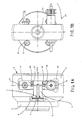
- FIGS. 1, 2, 3 An embodiment of the invention shown in FIGS. 1, 2, 3 is based on a combination of the yoke-shaped pump head with the associated mounting plate (3).
- the one-piece construction is chosen so that separate holding elements for the valve units, which form a kind of modules (11, 12), are not required.
- the fastening (assembly) flange (3) worked on the yoke body (2) is provided with countersunk bores (16) for the screws (17), which create the connection to the (not shown) drive unit of the pump.
- the actual pump head is formed by a narrow, very high yoke body (2), which is used to hold the (transparent) pump head sleeve (6) and the ceramic piston guide sleeve (4) Central, accessible from the front collar bore (18).
- the yoke body (2) is provided with corresponding lateral longitudinal slots (13). These slots run out at their rear ends in a T-shape so that the connection flushing tubes on the piston guide sleeve (4) can be aligned in a preferred inclined position.
- the longitudinal slots in the pump head yoke leave the wall of the receiving bore (18) in its mouth region untouched and lateral webs close the otherwise laterally open yoke body (2).
- a thread for an eyebolt (10) with a central hexagon hole is cut at the point described.
- the eyebolt is used to fix the ceramic piston guide sleeve (4) and the pump head sleeve (6).
- a flat sealing ring (5) made of PTFE film arranged between these two parts is a peripheral sealing element in the event of external flushing of the piston guide sleeve (4).
- Another identical flat sealing ring (9) between the pump head sleeve (6) and the fixing ring screw (10) is provided in order to act as a compensating element, which ensures an even distribution of the area of the load, which on the one hand is due to a certain very low tensioning of the pump head insert parts during assembly occurs in the receiving bore to each other, and on the other hand because of the contact forces that are to be absorbed by the pump head sleeve (6) on the front side as a result of the hydraulic loading during the conveying operation at high working pressures.
- the yoke body (2) of the pump head (1) is also penetrated by double T-shaped vertical recesses (14), which are also completely continuous and run from the side and cross the said longitudinal slots in the foremost area .
- the cutting area of the longitudinal and transverse slits is dimensioned such that the piston guide sleeve (4), which, owing to the flushing hose connection segments located thereon, because of the existing in the mouth area of the receiving bore, the yoke body (2) side bars that close here must not be installed from the front, can be inserted from the side at this point.
- the vertical openings (14) in the yoke body (2) of the pump head (1) serve both as viewing openings and as receiving slots for the modular valve units (11, 12) to be assembled from the side, whereby to achieve peripheral sealing their pre-tensioning the pump head sleeve (6) is made with the help of Allen screws (19), which are screwed into threaded holes in the cover webs above and below the vertical slide (14).
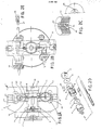
- the variant of this component does not assign the outer mouth of the inlet and outlet bores all-round, rim-shaped support profile on the valves.
- Such a support profile which has the task of counteracting deformation of the valve sealing rings made of filled PTFE (the special choice of material obeys the special operating conditions) as a result of cold flow, which occurs under the influence of the preload to which the parts involved are subject to achieve a peripheral seal, can be omitted here because only extremely thin flat seals (20) made of PTFE (FEP) film are used as corresponding sealing elements.
- the pump head sleeve (6) has been modified to accommodate this type of valve seal and has simple flat cuts (8) on the valve stub bores. Seen from above, these square cuts correspond in shape to the associated flat seals. A slight oversize in the edge length of the flat seals ensures sticking when inserted into the cuts (8) on the pump head sleeve (6).
- valve seals not only avoids the problem of deformation as a result of cold flow, but at the same time reduces the "harmful space" in the displacement system which has a negative effect on the pumping efficiency and which is defined as the dead volume in the area from the sealing edge of the inlet valve to the sealing edge of the outlet valve.
- valve units (11, 12) constructed according to the modular concept are characterized in that ...
- valve modules can also be inserted from the side into the corresponding receiving slots (14) in the pump head yoke with connected connecting lines.
- a peripheral seal is also achieved on the displacement system
- the pressure screws provided for this purpose do not transmit any torque to the valve modules (11, 12), because the modules and mounting slots have a congruent rectangular profile.
- exact alignment of the valve module (11, 12) and pump head sleeve (6) is ensured in that the pin of the pressure screw (19) engages in a corresponding cylindrical countersink on the rear of the valve module body (23, 24).
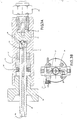
- the separable pipe or hose connections provided on the valve modules are based on a concept of multiple compatibility based on a special fitting screw (25).
- the bore of this screw is slightly tapered on the outlet side to achieve clamping of the ends of (PTFE) connecting hoses.
- PTFE PTFE
- With a varied bore diameter and in combination with suitably dimensioned plastic sleeves (26) of a T-shaped profile high or low pressure connections with different passage widths can be made using simple or coated PTFE capillary tubing.
- standard stainless steel capillary tubes can be connected.
- a special cutting ring (27) is used, which, contrary to the usual procedure, is aligned with its cone base towards the pipe end.
- a drain and ventilation device 15 is integrated in the valve module (11, 12), the central functional element of which forms a closing spindle (28) to be actuated by means of a knurled screw (29), which is guided through a plastic sleeve (31) and is biased by a plate spring arrangement (30).
- the closing spindle (28) is provided with a ruby ball (34) on its tip, which is touched by the flow, which presses in tangential contact on the associated tap hole in the plastic bushing (21) of the valve module body (23).
- the central drain hole (35) branches behind the closing ball crimped therein on the front (34) in a radial cross hole (33) to the outside.
- valve modules (15) modified in the manner described are used on the inlet side, the feed system can be filled with liquid from the storage container when the conveyor is started up by suction with the aid of a syringe.
- the configuration on the outlet side additionally allows the entire displacement area to be vented.
- the associated inner parts, seat (40), ball (41) and the ball guide (42 described elsewhere) with the ball stop fitted in a simple and for the purpose of achieving high pressure resistance, thick-walled sleeve as housing (43) arranged.
- This housing (43) can be made of sapphire, and in this case polished for transparency inside and outside, or if transparency is not required, made of zirconium oxide ceramic.
- valve seat (41) and ceramic ball guide / ball stop element (42) are freely displaceable in the associated housing sleeve (43), they each have a small bevel on the lateral surfaces, which in the installed state leads to a narrow gap towards the housing inner wall .
- the valve insert parts (40, 41, 42) can now be fixed in that a piece of microcapillary PTFE tube stretched for threading at one end is drawn into this gap (45) and subsequently cut flush. Alternatively, moistening the parts is sufficient to prevent them from slipping out of the housing sleeve.
Landscapes
- Engineering & Computer Science (AREA)
- Mechanical Engineering (AREA)
- General Engineering & Computer Science (AREA)
- Details Of Reciprocating Pumps (AREA)
Applications Claiming Priority (2)
| Application Number | Priority Date | Filing Date | Title |
|---|---|---|---|
| DE19863641652 DE3641652C2 (de) | 1986-12-05 | 1986-12-05 | Feindosierpumpe für Flüssigkeiten |
| DE3641652 | 1986-12-05 |
Publications (2)
| Publication Number | Publication Date |
|---|---|
| EP0270130A2 true EP0270130A2 (fr) | 1988-06-08 |
| EP0270130A3 EP0270130A3 (fr) | 1990-02-07 |
Family
ID=6315576
Family Applications (1)
| Application Number | Title | Priority Date | Filing Date |
|---|---|---|---|
| EP87117988A Withdrawn EP0270130A3 (fr) | 1986-12-05 | 1987-12-04 | Pompe de dosage précis pour fluides |
Country Status (2)
| Country | Link |
|---|---|
| EP (1) | EP0270130A3 (fr) |
| DE (1) | DE3641652C2 (fr) |
Cited By (5)
| Publication number | Priority date | Publication date | Assignee | Title |
|---|---|---|---|---|
| WO1994010445A1 (fr) * | 1992-10-28 | 1994-05-11 | Herbert Funke | Pompe haute pression pour le dosage precis de liquides |
| US5387334A (en) * | 1991-02-15 | 1995-02-07 | Toa Medical Electronics Co., Ltd. | Apparatus for regulating liquid temperature |
| WO1997031191A1 (fr) * | 1996-02-23 | 1997-08-28 | Waters Investments Limited | Configuration pour ensemble tete de pompe et piston a demontage facile |
| EP1384885A1 (fr) * | 2002-07-24 | 2004-01-28 | Dürr Systems GmbH | Dispositif pour le dosage ou le transport d'un fluide de transport |
| GB2540307B (en) * | 2014-03-31 | 2020-08-19 | Agilent Technologies Inc | Sealing moving with piston in a high-pressure pump |
Family Cites Families (5)
| Publication number | Priority date | Publication date | Assignee | Title |
|---|---|---|---|---|
| US4260342A (en) * | 1977-08-01 | 1981-04-07 | The Perkin-Elmer Corporation | Dual-piston reciprocating pump assembly |
| DK143719C (da) * | 1979-01-03 | 1982-03-08 | Radiometer As | Fremgangsmaade til udluftning af en vaeskedoserende stempelpumpe og stempelpumpe med et arrangement til brug ved udoevelse affremgangsmaaden |
| DE3122091C1 (de) * | 1981-06-03 | 1982-12-16 | Saphirwerk, Industrieprodukte AG Nidau, 2560 Nidau | Tauchkolbenpumpe |
| EP0228628A3 (fr) * | 1986-01-08 | 1989-07-26 | Saphirwerk Industrieprodukte AG | Pompe de dosage de précision pour des liquides, notamment pour l'usage dans la technologie HPLC |
| DE3600342A1 (de) * | 1986-01-08 | 1987-07-09 | Saphirwerk Ind Prod | Feindosierpumpe fuer fluessigkeiten, insbesondere zur anwendung in der hplc-technik |
-
1986
- 1986-12-05 DE DE19863641652 patent/DE3641652C2/de not_active Expired - Fee Related
-
1987
- 1987-12-04 EP EP87117988A patent/EP0270130A3/fr not_active Withdrawn
Cited By (6)
| Publication number | Priority date | Publication date | Assignee | Title |
|---|---|---|---|---|
| US5387334A (en) * | 1991-02-15 | 1995-02-07 | Toa Medical Electronics Co., Ltd. | Apparatus for regulating liquid temperature |
| WO1994010445A1 (fr) * | 1992-10-28 | 1994-05-11 | Herbert Funke | Pompe haute pression pour le dosage precis de liquides |
| WO1997031191A1 (fr) * | 1996-02-23 | 1997-08-28 | Waters Investments Limited | Configuration pour ensemble tete de pompe et piston a demontage facile |
| EP1225336A1 (fr) * | 1996-02-23 | 2002-07-24 | Waters Investments Limited | Pompe pour ensemble tête de pompe et piston à démontage facile |
| EP1384885A1 (fr) * | 2002-07-24 | 2004-01-28 | Dürr Systems GmbH | Dispositif pour le dosage ou le transport d'un fluide de transport |
| GB2540307B (en) * | 2014-03-31 | 2020-08-19 | Agilent Technologies Inc | Sealing moving with piston in a high-pressure pump |
Also Published As
| Publication number | Publication date |
|---|---|
| EP0270130A3 (fr) | 1990-02-07 |
| DE3641652C2 (de) | 1995-10-26 |
| DE3641652A1 (de) | 1988-06-16 |
Similar Documents
| Publication | Publication Date | Title |
|---|---|---|
| EP2488776B1 (fr) | Soupape de maintien de pression | |
| DE3151892A1 (de) | Handpumpe zur druckfoerderung von fluessigkeiten und/oder dickfluessigen substanzen aus einem behaelter | |
| DE2831642C2 (de) | Einstellbare Schmiermittelkolbenpumpe für sehr kleine Schmiermittelmengen | |
| DE102012108566A1 (de) | Fluidische Steckereinheit und Verbindungseinrichtung für Flüssigkeit führende Komponenten, insbesondere für die Hochleistungsflüssigkeitschromatographie | |
| DE69607945T2 (de) | Pumpe mit entlastungsventilsitz frei von direkter baulichen belastung | |
| DE69707237T2 (de) | Heizkörperventil | |
| DE102010035887B4 (de) | Dosiergerät für Flüssigkeiten | |
| DE3641652C2 (de) | Feindosierpumpe für Flüssigkeiten | |
| DE102004034231B4 (de) | Dosierpumpe | |
| DE8812456U1 (de) | Selbstdichtendes Ventil | |
| DE19614350A1 (de) | Pumpe, insbesondere Faßpumpe | |
| DE8525733U1 (de) | Membranpumpe | |
| DE3600341A1 (de) | Feindosierpumpe fuer fluessigkeiten, insbesondere zur anwendung in der hplc-technik | |
| DE19536258B4 (de) | Flaschendispenser | |
| DE102015103250B4 (de) | Dosiereinrichtung mit abnehmbarem Dosierkopf | |
| DE60202745T2 (de) | Flüssigkeitsinfusionsvorrichtung für Langzeitanwendung | |
| DE19716127C1 (de) | Extruderschnecke | |
| EP0547381A1 (fr) | Robinet à tournant sphérique | |
| DE9001274U1 (de) | Vorrichtung zur Kupplung eines unter Druck stehenden Vorratsbehälters mit einer Ausgabeeinrichtung | |
| EP0176528A1 (fr) | Organe d'etranglement pour la reduction de la pression dans des conduites de transport. | |
| DE3212089A1 (de) | Ventil | |
| EP0320700A1 (fr) | Dipositif pour éviter le reflux d'eau spécialement pour conduits d'eau potable | |
| DE202017003786U1 (de) | Ventilanordnung und Ventilbaugruppe | |
| DE2741749A1 (de) | Dosiergeraet fuer fluessigkeiten | |
| DE10310374A1 (de) | Dosiervorrichtung für insbesondere zähflüssige Flüssigkeiten |
Legal Events
| Date | Code | Title | Description |
|---|---|---|---|
| PUAI | Public reference made under article 153(3) epc to a published international application that has entered the european phase |
Free format text: ORIGINAL CODE: 0009012 |
|
| AK | Designated contracting states |
Kind code of ref document: A2 Designated state(s): CH DE FR GB LI NL SE |
|
| PUAL | Search report despatched |
Free format text: ORIGINAL CODE: 0009013 |
|
| AK | Designated contracting states |
Kind code of ref document: A3 Designated state(s): CH DE FR GB LI NL SE |
|
| 17P | Request for examination filed |
Effective date: 19900404 |
|
| 17Q | First examination report despatched |
Effective date: 19900905 |
|
| STAA | Information on the status of an ep patent application or granted ep patent |
Free format text: STATUS: THE APPLICATION IS DEEMED TO BE WITHDRAWN |
|
| 18D | Application deemed to be withdrawn |
Effective date: 19911015 |
|
| RIN1 | Information on inventor provided before grant (corrected) |
Inventor name: FUNKE, HERBERT, DR. |