EP0270136B1 - Windmühle mit verstellbaren Schaufeln - Google Patents
Windmühle mit verstellbaren Schaufeln Download PDFInfo
- Publication number
- EP0270136B1 EP0270136B1 EP87201656A EP87201656A EP0270136B1 EP 0270136 B1 EP0270136 B1 EP 0270136B1 EP 87201656 A EP87201656 A EP 87201656A EP 87201656 A EP87201656 A EP 87201656A EP 0270136 B1 EP0270136 B1 EP 0270136B1
- Authority
- EP
- European Patent Office
- Prior art keywords
- blades
- windmill according
- support
- vane
- windmill
- Prior art date
- Legal status (The legal status is an assumption and is not a legal conclusion. Google has not performed a legal analysis and makes no representation as to the accuracy of the status listed.)
- Expired - Lifetime
Links
- 230000007423 decrease Effects 0.000 claims description 3
- 239000003638 chemical reducing agent Substances 0.000 claims 1
- 238000010586 diagram Methods 0.000 description 3
- 238000004519 manufacturing process Methods 0.000 description 2
- 230000000712 assembly Effects 0.000 description 1
- 238000000429 assembly Methods 0.000 description 1
- 230000006378 damage Effects 0.000 description 1
- 238000013016 damping Methods 0.000 description 1
- 230000002349 favourable effect Effects 0.000 description 1
- XLYOFNOQVPJJNP-UHFFFAOYSA-N water Substances O XLYOFNOQVPJJNP-UHFFFAOYSA-N 0.000 description 1
Images



Classifications
-
- F—MECHANICAL ENGINEERING; LIGHTING; HEATING; WEAPONS; BLASTING
- F03—MACHINES OR ENGINES FOR LIQUIDS; WIND, SPRING, OR WEIGHT MOTORS; PRODUCING MECHANICAL POWER OR A REACTIVE PROPULSIVE THRUST, NOT OTHERWISE PROVIDED FOR
- F03D—WIND MOTORS
- F03D3/00—Wind motors with rotation axis substantially perpendicular to the air flow entering the rotor
- F03D3/06—Rotors
- F03D3/061—Rotors characterised by their aerodynamic shape, e.g. aerofoil profiles
-
- Y—GENERAL TAGGING OF NEW TECHNOLOGICAL DEVELOPMENTS; GENERAL TAGGING OF CROSS-SECTIONAL TECHNOLOGIES SPANNING OVER SEVERAL SECTIONS OF THE IPC; TECHNICAL SUBJECTS COVERED BY FORMER USPC CROSS-REFERENCE ART COLLECTIONS [XRACs] AND DIGESTS
- Y02—TECHNOLOGIES OR APPLICATIONS FOR MITIGATION OR ADAPTATION AGAINST CLIMATE CHANGE
- Y02E—REDUCTION OF GREENHOUSE GAS [GHG] EMISSIONS, RELATED TO ENERGY GENERATION, TRANSMISSION OR DISTRIBUTION
- Y02E10/00—Energy generation through renewable energy sources
- Y02E10/70—Wind energy
- Y02E10/74—Wind turbines with rotation axis perpendicular to the wind direction
Definitions
- the present invention relates to wind turbines, of the type consisting of a number of blades mounted on a support rotating about a vertical axis.
- the object of the invention is to produce a wind turbine, the design of which lends itself particularly well to mass production with economical equipment while obtaining good efficiency.
- the object of the invention is also to produce a wind turbine, which can respond instantly to all the vagaries of the horizontal wind, whether these are of speed or orientation.
- the invention is based on the phenomenon of the action of the wind on a blade made up of two blades with flat surface, whatever its shape, in a regular air flow, this action which is broken down into two forces namely the front thrust and rear drag. For small angles between the two blades the thrust increases rapidly, while the drag increases on the contrary slowly which is confirmed by the rotation of a wind turbine by a weak wind.
- a wind turbine according to the invention is of the type constituted by a number of blades mounted on a support rotating around a vertical axis, each blade being formed by a pair of blades joined together in the manner of a hinge, the l 'axis of rotation is connected to a horizontal arm of the rotating support and whose blades in the rest position are arranged substantially horizontally each blade being mounted on the same side on its support arm.
- V-shaped arrangement of the two blades forming the double blade has the advantage of breaking down the thrust and drag forces.
- a wind turbine with articulated blades is characterized according to the invention in that the free edge of the blades forming a blade has a curved profile such that the surface of the blade decreases towards the end opposite to the rotating support.
- this curved profile is calculated in such a way that the torque starting from the center of the rotating support is constant over the entire length of the blades.
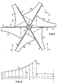
- the wind turbine consists of a vertical mast 1, on which is mounted so as to be able to rotate a support 2 provided with arms 3 extending radially relative to the mast. On each of these arms 3 is fixed a blade.
- Each blade is formed by a pair of 4.4 'blades joined together in the manner of a hinge and these blades are mounted on the arm 3 at the location of their axis of rotation 5.
- These blades 4.4' are arranged substantially horizontally, all on the same side of the arms 3.
- the light blades forming the blade are used to respond to the thrust of a light wind, given that for a stronger and continuous wind these light blades will stabilize in an ideal position.
- this set is called a stage, since several stages can be arranged in height on the same vertical axis.
- the blades 4, 4 ' can be initially maintained at a well-defined angle a and balanced by hinged springs, which will allow the blades to move in the direction (arrow x) imposed by the wind (arrow y), either opening or closing ( Figure 1).
- blades 4,4 ′ have a curved profile such that the surface of the blade decreases towards the end opposite to the rotating support 2.
- the profile of the blades as shown in the drawings can entail relatively high costs during manufacture and, consequently, it is understood that the blades could be in a less profiled form and be formed, for example, by a portion of blade a1-a8 instead of al-al 1 (figure 4).
- the profile view of the entire support is characterized by the opening of the blades facing the wind and the closing of the other blades, opening and closing controlled by the wind itself according to a horizontal level transmitting to the assembly of the desired power.
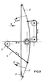
- FIG. 5 An example is given in FIG. 5 with a balancing by cable 6, pulleys 7 and damping spring 8 for low power apparatuses and in FIG. 6 with a balancing by gears 9 and hydraulic dampers for high power apparatus.
- a wind turbine according to the invention can be constituted by a single support 2 with arm 3 and blades 4,4 'called stage but it can also be made up of several stages on the same vertical axis 1.
- a wind vane is advantageously placed controlling, by a known system, the opening and closing of the blades in a portion of the most favorable circle to absorb the maximum of the energy of the wind.
- variable energy of the wind turbine is accumulated (figure 8) thanks to a reduction gear 10 in a spiral spring 11 releasing its accumulated energy to a flywheel 12 via an appropriate gearbox 13, the energy of the flywheel 12 being used intermittently.
Landscapes
- Engineering & Computer Science (AREA)
- Physics & Mathematics (AREA)
- Fluid Mechanics (AREA)
- Life Sciences & Earth Sciences (AREA)
- Sustainable Development (AREA)
- Sustainable Energy (AREA)
- Chemical & Material Sciences (AREA)
- Combustion & Propulsion (AREA)
- Mechanical Engineering (AREA)
- General Engineering & Computer Science (AREA)
- Wind Motors (AREA)
Claims (9)
Priority Applications (1)
| Application Number | Priority Date | Filing Date | Title |
|---|---|---|---|
| AT87201656T ATE57745T1 (de) | 1986-10-23 | 1987-09-01 | Windmuehle mit verstellbaren schaufeln. |
Applications Claiming Priority (2)
| Application Number | Priority Date | Filing Date | Title |
|---|---|---|---|
| BE6048264 | 1986-10-23 | ||
| BE6/48264A BE905646A (fr) | 1986-10-23 | 1986-10-23 | Eolienne. |
Publications (2)
| Publication Number | Publication Date |
|---|---|
| EP0270136A1 EP0270136A1 (de) | 1988-06-08 |
| EP0270136B1 true EP0270136B1 (de) | 1990-10-24 |
Family
ID=44615983
Family Applications (1)
| Application Number | Title | Priority Date | Filing Date |
|---|---|---|---|
| EP87201656A Expired - Lifetime EP0270136B1 (de) | 1986-10-23 | 1987-09-01 | Windmühle mit verstellbaren Schaufeln |
Country Status (4)
| Country | Link |
|---|---|
| EP (1) | EP0270136B1 (de) |
| AT (1) | ATE57745T1 (de) |
| BE (1) | BE905646A (de) |
| ES (1) | ES2018677B3 (de) |
Cited By (1)
| Publication number | Priority date | Publication date | Assignee | Title |
|---|---|---|---|---|
| RU2119093C1 (ru) * | 1996-12-03 | 1998-09-20 | Дальневосточный государственный технический университет | Ветродвигатель |
Family Cites Families (9)
| Publication number | Priority date | Publication date | Assignee | Title |
|---|---|---|---|---|
| DE203174C (de) * | ||||
| DE2571C (de) * | J. SANDER in Frankfurt a. M | Neuerungen an horizontalen Windrädern | ||
| FR23889E (fr) * | 1918-06-04 | 1922-01-13 | Severin Michel | Moulin à vent horizontal à volets tournants |
| GB188732A (en) * | 1921-08-09 | 1922-11-09 | James Robinson Scott | Horizontal windmill |
| FR812018A (fr) * | 1936-01-10 | 1937-04-28 | Procédé de fabrication de pales en tôle d'acier ou autre métal | |
| US2441635A (en) * | 1945-06-12 | 1948-05-18 | Henry V Iverson | Windmill |
| FR998721A (fr) * | 1949-10-06 | 1952-01-22 | Appareil à volets automatiquement mobiles sous la force et la direction du vent, captant cette dite force et la transformant en énergie motrice | |
| FR2292878A1 (fr) * | 1974-09-30 | 1976-06-25 | Sahores Jean | Moteur eolien |
| DE3117995A1 (de) * | 1981-05-07 | 1982-11-25 | Ficht GmbH, 8011 Kirchseeon | Rotor fuer eine windkraftanlage |
-
1986
- 1986-10-23 BE BE6/48264A patent/BE905646A/fr not_active IP Right Cessation
-
1987
- 1987-09-01 EP EP87201656A patent/EP0270136B1/de not_active Expired - Lifetime
- 1987-09-01 AT AT87201656T patent/ATE57745T1/de not_active IP Right Cessation
- 1987-09-01 ES ES87201656T patent/ES2018677B3/es not_active Expired - Lifetime
Cited By (1)
| Publication number | Priority date | Publication date | Assignee | Title |
|---|---|---|---|---|
| RU2119093C1 (ru) * | 1996-12-03 | 1998-09-20 | Дальневосточный государственный технический университет | Ветродвигатель |
Also Published As
| Publication number | Publication date |
|---|---|
| EP0270136A1 (de) | 1988-06-08 |
| ES2018677B3 (es) | 1991-05-01 |
| BE905646A (fr) | 1987-02-16 |
| ATE57745T1 (de) | 1990-11-15 |
Similar Documents
| Publication | Publication Date | Title |
|---|---|---|
| CA2018199C (fr) | Eolienne a stator | |
| EP0064440A2 (de) | Doppeltradwindkraftgenerator mit senkrechter Welle und kanalisiertem Windstrom | |
| EP2572100B1 (de) | Turbogenerator mit rotor und rotorblätter, die sich an den scheinbaren wind anpassen | |
| EP1961956A1 (de) | Windkraftanlage mit vertikaler Achse | |
| FR2472093A1 (fr) | Eolienne a rotor monte dans un entonnoir-avaloir | |
| EP2534430B1 (de) | Sonnenkollektor mit fresnel-spiegeln | |
| EP1907696B1 (de) | Windkraftmotor | |
| CA2719144C (fr) | Pale pour appareil de generation d'energie, a partir d'un fluide, et appareil comprenant un rotor faisant application de telles pales | |
| EP2307711B1 (de) | Einlassvorrichtung für eine umweltfreundliche hydraulische turbomaschine | |
| FR2908840A1 (fr) | Eolienne a axe vertical avec enceinte pour environnement urbain | |
| EP1618300A2 (de) | Verstellbare mantelwindturbine | |
| WO2015189155A1 (fr) | Rotor éolien de type savonius | |
| EP0270136A1 (de) | Windmühle mit verstellbaren Schaufeln | |
| FR2930974A1 (fr) | Eolienne verticale a profil variable et auto-regulation | |
| CA2755083A1 (fr) | Rotor pour generateur d'energie, en particulier pour eoliennes. | |
| FR2965592A1 (fr) | Eolienne | |
| FR2488337A1 (fr) | Eolienne a roues multiples d'axe horizontal, carenees et juxtaposees | |
| FR2859247A1 (fr) | Eolienne a axe vertical | |
| WO2004063565A1 (fr) | Dispositif concentrateur de vent pour eolienne a axe vertical | |
| FR2520057A1 (fr) | Perfectionnement aux aerogenerateurs | |
| FR2899651A1 (fr) | Eolienne a axe vertical avec enceinte pour environnement urbain | |
| EP0069208A1 (de) | Windrad mit divergierender Wirkung | |
| FR2902157A1 (fr) | Eolienne a axe vertical comprenant une turbine et une gaine co-axiale a ladite turbine et enveloppant cette derniere | |
| BE1029739B1 (fr) | Éolienne à axe perpendiculaire à la direction du vent | |
| FR3076581A1 (fr) | Aerogenerateur a axe vertical |
Legal Events
| Date | Code | Title | Description |
|---|---|---|---|
| PUAI | Public reference made under article 153(3) epc to a published international application that has entered the european phase |
Free format text: ORIGINAL CODE: 0009012 |
|
| AK | Designated contracting states |
Kind code of ref document: A1 Designated state(s): AT BE CH DE ES FR GB GR IT LI LU NL SE |
|
| 17P | Request for examination filed |
Effective date: 19880902 |
|
| 17Q | First examination report despatched |
Effective date: 19891214 |
|
| GRAA | (expected) grant |
Free format text: ORIGINAL CODE: 0009210 |
|
| AK | Designated contracting states |
Kind code of ref document: B1 Designated state(s): AT BE CH DE ES FR GB GR IT LI LU NL SE |
|
| PG25 | Lapsed in a contracting state [announced via postgrant information from national office to epo] |
Ref country code: SE Effective date: 19901024 Ref country code: GR Free format text: LAPSE BECAUSE OF FAILURE TO SUBMIT A TRANSLATION OF THE DESCRIPTION OR TO PAY THE FEE WITHIN THE PRESCRIBED TIME-LIMIT Effective date: 19901024 |
|
| REF | Corresponds to: |
Ref document number: 57745 Country of ref document: AT Date of ref document: 19901115 Kind code of ref document: T |
|
| REF | Corresponds to: |
Ref document number: 3765755 Country of ref document: DE Date of ref document: 19901129 |
|
| ITF | It: translation for a ep patent filed | ||
| GBT | Gb: translation of ep patent filed (gb section 77(6)(a)/1977) | ||
| PLBE | No opposition filed within time limit |
Free format text: ORIGINAL CODE: 0009261 |
|
| STAA | Information on the status of an ep patent application or granted ep patent |
Free format text: STATUS: NO OPPOSITION FILED WITHIN TIME LIMIT |
|
| ITTA | It: last paid annual fee | ||
| 26N | No opposition filed | ||
| PGFP | Annual fee paid to national office [announced via postgrant information from national office to epo] |
Ref country code: LU Payment date: 19920812 Year of fee payment: 6 |
|
| PGFP | Annual fee paid to national office [announced via postgrant information from national office to epo] |
Ref country code: GB Payment date: 19920828 Year of fee payment: 6 |
|
| PGFP | Annual fee paid to national office [announced via postgrant information from national office to epo] |
Ref country code: ES Payment date: 19920910 Year of fee payment: 6 |
|
| PGFP | Annual fee paid to national office [announced via postgrant information from national office to epo] |
Ref country code: AT Payment date: 19920916 Year of fee payment: 6 |
|
| PGFP | Annual fee paid to national office [announced via postgrant information from national office to epo] |
Ref country code: FR Payment date: 19920924 Year of fee payment: 6 |
|
| PGFP | Annual fee paid to national office [announced via postgrant information from national office to epo] |
Ref country code: BE Payment date: 19920925 Year of fee payment: 6 |
|
| PGFP | Annual fee paid to national office [announced via postgrant information from national office to epo] |
Ref country code: DE Payment date: 19920929 Year of fee payment: 6 |
|
| PGFP | Annual fee paid to national office [announced via postgrant information from national office to epo] |
Ref country code: NL Payment date: 19920930 Year of fee payment: 6 |
|
| PGFP | Annual fee paid to national office [announced via postgrant information from national office to epo] |
Ref country code: CH Payment date: 19921125 Year of fee payment: 6 |
|
| EPTA | Lu: last paid annual fee | ||
| PG25 | Lapsed in a contracting state [announced via postgrant information from national office to epo] |
Ref country code: LU Free format text: LAPSE BECAUSE OF NON-PAYMENT OF DUE FEES Effective date: 19930901 Ref country code: GB Effective date: 19930901 Ref country code: AT Effective date: 19930901 |
|
| PG25 | Lapsed in a contracting state [announced via postgrant information from national office to epo] |
Ref country code: ES Free format text: LAPSE BECAUSE OF THE APPLICANT RENOUNCES Effective date: 19930902 |
|
| PG25 | Lapsed in a contracting state [announced via postgrant information from national office to epo] |
Ref country code: LI Effective date: 19930930 Ref country code: CH Effective date: 19930930 Ref country code: BE Effective date: 19930930 |
|
| BERE | Be: lapsed |
Owner name: SCHUURWEGEN HORACE Effective date: 19930930 |
|
| PG25 | Lapsed in a contracting state [announced via postgrant information from national office to epo] |
Ref country code: NL Effective date: 19940401 |
|
| GBPC | Gb: european patent ceased through non-payment of renewal fee |
Effective date: 19930901 |
|
| NLV4 | Nl: lapsed or anulled due to non-payment of the annual fee | ||
| PG25 | Lapsed in a contracting state [announced via postgrant information from national office to epo] |
Ref country code: FR Free format text: LAPSE BECAUSE OF NON-PAYMENT OF DUE FEES Effective date: 19940531 |
|
| REG | Reference to a national code |
Ref country code: CH Ref legal event code: PL |
|
| PG25 | Lapsed in a contracting state [announced via postgrant information from national office to epo] |
Ref country code: DE Effective date: 19940601 |
|
| REG | Reference to a national code |
Ref country code: FR Ref legal event code: ST |
|
| REG | Reference to a national code |
Ref country code: ES Ref legal event code: FD2A Effective date: 19991007 |
|
| PG25 | Lapsed in a contracting state [announced via postgrant information from national office to epo] |
Ref country code: IT Free format text: LAPSE BECAUSE OF NON-PAYMENT OF DUE FEES;WARNING: LAPSES OF ITALIAN PATENTS WITH EFFECTIVE DATE BEFORE 2007 MAY HAVE OCCURRED AT ANY TIME BEFORE 2007. THE CORRECT EFFECTIVE DATE MAY BE DIFFERENT FROM THE ONE RECORDED. Effective date: 20050901 |