EP0270140A1 - Verfahren und Vorrichtung zum Entfernen eines Schussfehlers in Webmaschinen - Google Patents
Verfahren und Vorrichtung zum Entfernen eines Schussfehlers in Webmaschinen Download PDFInfo
- Publication number
- EP0270140A1 EP0270140A1 EP87201927A EP87201927A EP0270140A1 EP 0270140 A1 EP0270140 A1 EP 0270140A1 EP 87201927 A EP87201927 A EP 87201927A EP 87201927 A EP87201927 A EP 87201927A EP 0270140 A1 EP0270140 A1 EP 0270140A1
- Authority
- EP
- European Patent Office
- Prior art keywords
- releasing
- thread
- cloth line
- weft thread
- elements
- Prior art date
- Legal status (The legal status is an assumption and is not a legal conclusion. Google has not performed a legal analysis and makes no representation as to the accuracy of the status listed.)
- Granted
Links
- 238000000034 method Methods 0.000 title claims abstract description 24
- 238000009941 weaving Methods 0.000 title claims abstract description 14
- 239000004744 fabric Substances 0.000 claims abstract description 55
- 235000014676 Phragmites communis Nutrition 0.000 claims abstract description 10
- 239000004020 conductor Substances 0.000 claims description 2
- 238000001514 detection method Methods 0.000 description 3
- 238000003780 insertion Methods 0.000 description 2
- 230000037431 insertion Effects 0.000 description 2
- 230000002950 deficient Effects 0.000 description 1
- 230000003287 optical effect Effects 0.000 description 1
Images


Classifications
-
- D—TEXTILES; PAPER
- D03—WEAVING
- D03D—WOVEN FABRICS; METHODS OF WEAVING; LOOMS
- D03D51/00—Driving, starting, or stopping arrangements; Automatic stop motions
- D03D51/06—Driving, starting, or stopping arrangements; Automatic stop motions using particular methods of stopping
- D03D51/08—Driving, starting, or stopping arrangements; Automatic stop motions using particular methods of stopping stopping at definite point in weaving cycle, or moving to such point after stopping
- D03D51/085—Extraction of defective weft
Definitions
- This invention relates to a method for releasing faulty weft threads in weaving machines, in other words, a method for freeing a beaten-up faulty weft thread again in the shed in a manner such that it can readily be removed therefrom.
- the invention furthermore relates also to devices which use said method.
- a weaving machine is known from the Dutch Patent Application no. 82 04665 which contains means for removing defective weft threads from the shed.
- the means used in this case provide for an element which can be moved to and fro through the shed to be introduced from the insertion side of the weaving machine, which element is passed between the cloth line and the thread to be released.
- this device has the disadvantage that the element which can be moved to and fro moves along the weft direction over the warp threads and consequently can catch on the latter and damage them.
- Another disadvantage of said device is that it is only suitable for releasing sections of thread which are located at the insertion side of the machine. In the case of a broken weft thread, the other section of thread is not released.
- Yet another disadvantage of this device is that it requires a lot of space at the entrance of the shed and this entails difficulties in siting the other necessary components.
- a device is also known from the Dutch Patent Application no. 82 02215 for releasing faulty weft threads.
- the faulty weft thread is released at a number of points in the shed and then drawn through the uppermost warp threads.
- the actual release of the faulty weft thread is carried out by allowing a hook-shaped element to slide over the cloth until it reaches the vicinity of the cloth line, the beaten-up faulty weft thread, which has already been beaten-up but not yet fixed in position, being released and taken to the centre of the shed.
- This device does not, however, offer complete reliability in relation to releasing the faulty weft thread since, if the latter is securely clamped between the warp threads, the needle-shaped element will slide over the faulty weft thread and completely miss its object.
- a shuttleless weaving machine is known from the British Patent no. 1.430.520 in which a faulty weft thread, more particularly a broken weft thread, is removed from the shed from either side by means of devices installed next to the shed.
- the present invention relates to a method for releasing faulty weft threads and also to a device which uses said method, the above-mentioned disadvantages being systematically eliminated.
- the method for releasing faulty weft threads has the characteristic that it essentially consists in : - eliminating the binding between the faulty weft thread and the warp threads ; - initially releasing or holding the weft thread free near the fabric edge or edges by moving the associated thread end or both thread ends thereof away from the cloth line or holding it apart ; - positioning at least one releasing element or releasing elements between the cloth line and the released thread end or the released thread ends ; - releasing the thread end or the thread ends over a further distance by moving the releasing element or releasing elements away from the cloth line in the direction of the reed ; - repositioning a releasing element between the weft thread section or weft thread sections thus released, and the cloth line ; - in turn releasing over a further distance the weft thread by moving the last-mentioned releasing element away from the cloth line in the direction of the reed ; - and continuing the last-named two steps in the shed stepwise
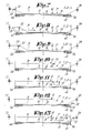
- FIGmatic depictions in figures 1 to 5 inclusive show the uppermost warp threads 1, the undermost warp threads 2, the shed 3, the fabric 4 and the cloth line 5. Furthermore, a faulty weft thread 6 is indicated which consists, for example as a result of a thread break 7, of two weft thread sections 8 and 9. The weft thread 6 is still connected to the thread feed 10, for example via a thread eye or thread clamp 11. According to this embodiment, use is furthermore made of two movable needle- or pin-type releasing elements 12 and 13. During the normal weaving process, said releasing elements 12 and 13 are located outside the shed 3 and in front of the fabric edge 14 or the extension thereof.
- the second releasing element 13 is placed next to the first as shown in figure 3.
- the first releasing element 12 is then moved upwards, moved over the warp threads 1, moved back in the direction of the cloth line 5 and then lowered through the warp threads 1 into the shed, all this in a manner such that said releasing element 13 is positioned just next to the cloth line 5 inside the above-mentioned distance A and behind the weft thread 6.
- the weft thread 6, more particularly the thread section 8 is released over a further distance B.
- the releasing element 13 ensures that the weft thread 6 always remains taut, otherwise the latter could not be released by the releasing element 12.
- the releasing element 13 is again placed next to the first releasing element 12 in a subsequent step.
- a complete operation is build up in which, in a stepwise advancing movement V, the faulty weft thread 6, or at least the weft thread section 8, is released.
- the released weft thread section 8 can then easily be removed from the shed by thread removal means known per se.
- this weft thread section 8 will be removed, for example at the other fabric edge 16, from the shed 3, as shown in figure 6, by introducing a new weft thread 17 which is entrained by the section 8 in the form of a loop.
- the releasing elements 12 and 13 are always positioned between an already previously removed section of the weft thread 6 and the cloth line 5, the thread to be released is gripped in a positive manner, this being in contrast to the device of the above-mentioned Dutch Patent Application no 82 02215 in which the releasing elements have to be forced between the cloth line and the faulty weft thread.
- the operation to free the weft thread 6 may start not only from the fabric edge 14, but that it can also start from the opposite fabric edge 16 (figure 6), in other words by executing an operation by means of releasing elements 12 and 13 following a movement W, this being in order to free the second weft thread section 9.
- the thread end of the weft thread 6 is completely woven in near the fabric edge 16, it should first be pulled free by means of movable clamping means 18 known per se, for example a mechanical clamp or a suction nozzle, in a manner such that a free space 19 is created for the initial positioning of the releasing elements 12 and 13.
- the release of the weft thread section 9 then takes place in an analogous manner as described with reference to figures 1 to 5 inclusive.
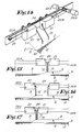
- Figure 14 shows an example of a device for releasing the faulty weft threads.
- the above-mentioned releasing elements 12 and 13 are in this case embodied in needle form and are respectively mounted on two small carriages or the like, 20 and 21.
- Drive means which are not shown in the figures are provided in the small carriages 20 and 21 in order to move the releasing elements 12 and 13 through the warp threads 1 and 2 in and out of the shed 3 precisely in order to provide the necessary to and fro movement in the shed 3.
- the small carriages 20 and 21 form the means of moving the releasing elements 12 and 13 and they therefore provide the stepwise movement thereof.
- Said small carriages 20 and 21 are provided with a drive which is formed by cable connections 22A and 22B and stepping motors 23A and 23B.
- the small carriage 21 is connected to the small carriage 20 by means of elastic means 24, such as, for example, a tension spring.
- the small carriages 22A and 22B each furthermore contain a braking or locking mechanism in a manner such that they can be locked with respect to the guide 25.
- FIG 15 The operation of the device according to figure 14 is shown diagrammatically in figures 15 to 17 inclusive for above-mentioned movement W.
- the small carriages are up against each other.
- the small carriage 20 is advanced, while the small carriage 21 is locked.
- the spring 24 is stretched.
- the releasing element 12 is then set in operation, a release cycle being executed as described above.
- the needle 13 is then removed from the shed 3 and the locking machanism of the small carriage 21 is released.
- the tension spring 24 pulls the second small carriage 21 back up against the first small carriage 20.
- the releasing element 13 is then lowered again, as shown in figure 17.
- the preceding steps can then be executed repeatedly.
- control takes place via the cable connections 22A and/or 22B which are constructed as electrical conductors along which control signals can be transmitted.
- FIG. 18 therefore shows diagrammatically a device in which use is made of releasing elements 26 to 33 inclusive which are distributed over the complete weaving width in the vicinity of the cloth line 5 and are situated in the rest state above or below the shed.
- a possible operation procedure thereof is shown stepwise in figures 18 to 31 inclusive.
- the releasing elements 26 to 33 inclusive are represented by means of small crosses if they are situated ouside the shed 3, and by means of dots if they are positioned in the shed.
- the weft thread 6 is, of course, first released initially near the fabric edges 14 and 16, for example by means of clamps 34 to 35. As shown in figure 19, a release element, 26 and 33 respectively, is then lowered at both ends of the shed 3, and they finish up between the cloth line 5 and the respective weft thread sections 8 and 9.
- the method according to the invention is then executed from both ends, by means of the movements V and W respectively.
- the releasing elements are, of course, provided with the necessary drive and control means to execute the above-mentioned steps in a suitable manner.
- the above-mentioned releasing elements 12, 13 and 16 to 33 inclusive are provided with thread detectors 36.
- these consist, for example, of two optical detection elements 37 and 38 situated opposite each other.
- mechanical detectors or the like can also be used.
- the detection elements 37 and 38 are placed in a manner such that they can detect the thread concerned during the forward movement 39.
- the use of the thread detectors 36 offers the advantage that the above-mentioned releasing elements do not always have to operate over the complete width of the machine, but only over the distance in which the weft thread section concerned is present. With reference to the embodiment in figures 18 to 31 inclusive, this means that the operation by means of the movement W is interrupted when the situation in figure 22 is reached since weft thread is no longer detected at the releasing element 31, while the operation by means of the movement V is continued until the situation in figure 27.
- the thread detectors 36 it is also possible to detect whether all the thread has been removed from the shed 3.
- the releasing elements 12 and 13, or respectively 26 to 33 inclusive, describe preferably a rectangular path 40 as shown in figure 33. Providing first an upwards movement 41 after the forwards movement 39 and then only a return movement 42 prevents the weft thread 6 which has been forced loose being carried back to the cloth line 5, for example because it has caught on the releasing element.
Landscapes
- Engineering & Computer Science (AREA)
- Textile Engineering (AREA)
- Looms (AREA)
Applications Claiming Priority (2)
| Application Number | Priority Date | Filing Date | Title |
|---|---|---|---|
| NL8602827 | 1986-11-07 | ||
| NL8602827A NL8602827A (nl) | 1986-11-07 | 1986-11-07 | Werkwijze voor het losmaken van foutieve inslagdraden bij weefmachines en inrichting hierbij aangewend. |
Publications (2)
| Publication Number | Publication Date |
|---|---|
| EP0270140A1 true EP0270140A1 (de) | 1988-06-08 |
| EP0270140B1 EP0270140B1 (de) | 1990-07-04 |
Family
ID=19848804
Family Applications (1)
| Application Number | Title | Priority Date | Filing Date |
|---|---|---|---|
| EP87201927A Expired EP0270140B1 (de) | 1986-11-07 | 1987-10-08 | Verfahren und Vorrichtung zum Entfernen eines Schussfehlers in Webmaschinen |
Country Status (5)
| Country | Link |
|---|---|
| US (1) | US4821779A (de) |
| EP (1) | EP0270140B1 (de) |
| DE (1) | DE3763580D1 (de) |
| ES (1) | ES2015947B3 (de) |
| NL (1) | NL8602827A (de) |
Families Citing this family (3)
| Publication number | Priority date | Publication date | Assignee | Title |
|---|---|---|---|---|
| FR2659361B1 (fr) * | 1990-03-06 | 1994-07-29 | Saurer Diederichs Sa | Dispositif de detissage automatique pour machines a tisser avec organes d'insertion mecanique de la trame. |
| JP2930739B2 (ja) * | 1990-12-28 | 1999-08-03 | 津田駒工業株式会社 | 不良糸除去方法 |
| JP2003342857A (ja) * | 2002-05-28 | 2003-12-03 | Tsudakoma Corp | 織機における緯糸処理方法 |
Citations (5)
| Publication number | Priority date | Publication date | Assignee | Title |
|---|---|---|---|---|
| FR2248353A1 (de) * | 1973-10-20 | 1975-05-16 | Dornier Gmbh Lindauer | |
| FR2527655A1 (fr) * | 1982-06-01 | 1983-12-02 | Rueti Te Strake Bv | Metier a tisser sans navette comprenant un moyen pour retirer des fils defectueux de trame, de la foule |
| EP0100939A2 (de) * | 1982-07-21 | 1984-02-22 | Kabushiki Kaisha Toyoda Jidoshokki Seisakusho | Verfahren und Vorrichtung zum Behandeln eines Schussfadens nach Stillsetzen eines schützenlosen Webstuhls |
| FR2537168A1 (fr) * | 1982-12-01 | 1984-06-08 | Rueti Te Strake Bv | Metier a tisser sans navette comprenant un moyen pour retirer, de la foule, des fils defectueux de trame |
| DE3537714A1 (de) * | 1984-10-24 | 1986-04-30 | Kabushiki Kaisha Toyoda Jidoshokki Seisakusho, Kariya, Aichi | Verfahren zur handhabung eines schussfadens in einer schuetzenlosen webmaschine und vorrichtung zur durchfuehrung des verfahrens |
Family Cites Families (2)
| Publication number | Priority date | Publication date | Assignee | Title |
|---|---|---|---|---|
| US3805850A (en) * | 1972-06-09 | 1974-04-23 | Maschf Te Strake L Nv | Control device for repairing weaving defects in a pneumatic weaving machine |
| KR890000569Y1 (ko) * | 1985-01-09 | 1989-03-11 | 쯔다고마 고오교오 가부시끼 가이샤 | 셔틀리스 (Shuttleless) 직기의 불량사 제거장치 |
-
1986
- 1986-11-07 NL NL8602827A patent/NL8602827A/nl not_active Application Discontinuation
-
1987
- 1987-10-08 EP EP87201927A patent/EP0270140B1/de not_active Expired
- 1987-10-08 ES ES87201927T patent/ES2015947B3/es not_active Expired - Lifetime
- 1987-10-08 DE DE8787201927T patent/DE3763580D1/de not_active Expired - Lifetime
- 1987-10-27 US US07/113,077 patent/US4821779A/en not_active Expired - Fee Related
Patent Citations (5)
| Publication number | Priority date | Publication date | Assignee | Title |
|---|---|---|---|---|
| FR2248353A1 (de) * | 1973-10-20 | 1975-05-16 | Dornier Gmbh Lindauer | |
| FR2527655A1 (fr) * | 1982-06-01 | 1983-12-02 | Rueti Te Strake Bv | Metier a tisser sans navette comprenant un moyen pour retirer des fils defectueux de trame, de la foule |
| EP0100939A2 (de) * | 1982-07-21 | 1984-02-22 | Kabushiki Kaisha Toyoda Jidoshokki Seisakusho | Verfahren und Vorrichtung zum Behandeln eines Schussfadens nach Stillsetzen eines schützenlosen Webstuhls |
| FR2537168A1 (fr) * | 1982-12-01 | 1984-06-08 | Rueti Te Strake Bv | Metier a tisser sans navette comprenant un moyen pour retirer, de la foule, des fils defectueux de trame |
| DE3537714A1 (de) * | 1984-10-24 | 1986-04-30 | Kabushiki Kaisha Toyoda Jidoshokki Seisakusho, Kariya, Aichi | Verfahren zur handhabung eines schussfadens in einer schuetzenlosen webmaschine und vorrichtung zur durchfuehrung des verfahrens |
Also Published As
| Publication number | Publication date |
|---|---|
| ES2015947B3 (es) | 1990-09-16 |
| NL8602827A (nl) | 1988-06-01 |
| EP0270140B1 (de) | 1990-07-04 |
| US4821779A (en) | 1989-04-18 |
| DE3763580D1 (de) | 1990-08-09 |
Similar Documents
| Publication | Publication Date | Title |
|---|---|---|
| US4840203A (en) | Process for clamping, fastening and presentation of weft threads in gripper weaving looms and device used to this end | |
| US4941513A (en) | Method for removing an incorrect piece of weft thread from a shed | |
| EP0270140B1 (de) | Verfahren und Vorrichtung zum Entfernen eines Schussfehlers in Webmaschinen | |
| US3384126A (en) | Weft thread inserting device in weaving machines | |
| US4974640A (en) | Method for removing a loose incorrect piece of weft thread from the shed on weaving machines | |
| US5411063A (en) | Seam-weaving machine with fringe catcher | |
| RU2051229C1 (ru) | Ткацкий станок с зажимными челноками и способ устранения оборванной уточной нити на этом станке | |
| US3237656A (en) | Weaving loom comprising a device for the guiding and supervision of the weft thread | |
| CN109208158B (zh) | 在片梭织机中不使用假边的纬纱操作装置 | |
| US4140156A (en) | Weft strand positioning at the exit end of the shed in a weaving machine | |
| US4014083A (en) | Draw-in gripper assembly for drawing-in warp threads | |
| GB2129449A (en) | A shuttleless weaving loom having apparatus for forming a selvage | |
| US3299909A (en) | Selective weft presenting device | |
| EP0330023A1 (de) | Methode zum Vorbereiten und Bergen eines defekten Schussfadens aus dem offenen Webfach für Düsenwebmaschinen | |
| DE69125805T2 (de) | Verfahren zum Entfernen eines fehlerhaften Schussfadens | |
| US4875507A (en) | Process and apparatus for guiding the weft threads in weaving looms | |
| DE1535615B2 (de) | Schußfadenwächter für Greiferschützenwebmaschine | |
| CS56691A2 (en) | Device for automatic splitting for looms with weft's mechanical carriers | |
| CN101454491A (zh) | 用于在剑杆织机上形成织物边的方法和装置 | |
| DE69607973T2 (de) | Verfahren zum automatischen entfernen eines falschen schussfadens aus dem webfach einer greiferwebmaschine | |
| US3536105A (en) | Looms | |
| EP0311170A1 (de) | Verfahren zur Wiederherstellung von gebrochenen Kettenfäden an Webmaschinen | |
| EP2006430B1 (de) | Teilungsvorrichtung und Verfahren zur Entfernung eines fehlerhaften Schussfadens in einer Webmaschine | |
| KR860001418B1 (ko) | 젯트직기의 정지시의 위사처리방법 | |
| US2816577A (en) | Looms for weaving |
Legal Events
| Date | Code | Title | Description |
|---|---|---|---|
| PUAI | Public reference made under article 153(3) epc to a published international application that has entered the european phase |
Free format text: ORIGINAL CODE: 0009012 |
|
| AK | Designated contracting states |
Kind code of ref document: A1 Designated state(s): BE CH DE ES FR GB IT LI LU NL |
|
| 17P | Request for examination filed |
Effective date: 19880624 |
|
| 17Q | First examination report despatched |
Effective date: 19891124 |
|
| GRAA | (expected) grant |
Free format text: ORIGINAL CODE: 0009210 |
|
| AK | Designated contracting states |
Kind code of ref document: B1 Designated state(s): BE CH DE ES FR GB IT LI LU NL |
|
| REF | Corresponds to: |
Ref document number: 3763580 Country of ref document: DE Date of ref document: 19900809 |
|
| ET | Fr: translation filed | ||
| ITF | It: translation for a ep patent filed | ||
| PGFP | Annual fee paid to national office [announced via postgrant information from national office to epo] |
Ref country code: NL Payment date: 19901031 Year of fee payment: 4 |
|
| EPTA | Lu: last paid annual fee | ||
| PLBE | No opposition filed within time limit |
Free format text: ORIGINAL CODE: 0009261 |
|
| STAA | Information on the status of an ep patent application or granted ep patent |
Free format text: STATUS: NO OPPOSITION FILED WITHIN TIME LIMIT |
|
| 26N | No opposition filed | ||
| PGFP | Annual fee paid to national office [announced via postgrant information from national office to epo] |
Ref country code: GB Payment date: 19911008 Year of fee payment: 5 Ref country code: FR Payment date: 19911008 Year of fee payment: 5 |
|
| PGFP | Annual fee paid to national office [announced via postgrant information from national office to epo] |
Ref country code: BE Payment date: 19911011 Year of fee payment: 5 |
|
| PGFP | Annual fee paid to national office [announced via postgrant information from national office to epo] |
Ref country code: CH Payment date: 19911028 Year of fee payment: 5 |
|
| PGFP | Annual fee paid to national office [announced via postgrant information from national office to epo] |
Ref country code: ES Payment date: 19911030 Year of fee payment: 5 |
|
| ITTA | It: last paid annual fee | ||
| PGFP | Annual fee paid to national office [announced via postgrant information from national office to epo] |
Ref country code: DE Payment date: 19911218 Year of fee payment: 5 |
|
| PG25 | Lapsed in a contracting state [announced via postgrant information from national office to epo] |
Ref country code: NL Effective date: 19920501 |
|
| NLV4 | Nl: lapsed or anulled due to non-payment of the annual fee | ||
| PG25 | Lapsed in a contracting state [announced via postgrant information from national office to epo] |
Ref country code: GB Effective date: 19921008 |
|
| PG25 | Lapsed in a contracting state [announced via postgrant information from national office to epo] |
Ref country code: ES Free format text: LAPSE BECAUSE OF THE APPLICANT RENOUNCES Effective date: 19921009 |
|
| PG25 | Lapsed in a contracting state [announced via postgrant information from national office to epo] |
Ref country code: LI Effective date: 19921031 Ref country code: CH Effective date: 19921031 Ref country code: BE Effective date: 19921031 |
|
| BERE | Be: lapsed |
Owner name: PICANOL N.V. Effective date: 19921031 |
|
| GBPC | Gb: european patent ceased through non-payment of renewal fee |
Effective date: 19921008 |
|
| PG25 | Lapsed in a contracting state [announced via postgrant information from national office to epo] |
Ref country code: FR Effective date: 19930630 |
|
| REG | Reference to a national code |
Ref country code: CH Ref legal event code: PL |
|
| PG25 | Lapsed in a contracting state [announced via postgrant information from national office to epo] |
Ref country code: DE Effective date: 19930701 |
|
| REG | Reference to a national code |
Ref country code: FR Ref legal event code: ST |
|
| PGFP | Annual fee paid to national office [announced via postgrant information from national office to epo] |
Ref country code: LU Payment date: 19961031 Year of fee payment: 10 |
|
| PG25 | Lapsed in a contracting state [announced via postgrant information from national office to epo] |
Ref country code: LU Free format text: LAPSE BECAUSE OF NON-PAYMENT OF DUE FEES Effective date: 19971008 |
|
| REG | Reference to a national code |
Ref country code: ES Ref legal event code: FD2A Effective date: 19991007 |
|
| PG25 | Lapsed in a contracting state [announced via postgrant information from national office to epo] |
Ref country code: IT Free format text: LAPSE BECAUSE OF NON-PAYMENT OF DUE FEES;WARNING: LAPSES OF ITALIAN PATENTS WITH EFFECTIVE DATE BEFORE 2007 MAY HAVE OCCURRED AT ANY TIME BEFORE 2007. THE CORRECT EFFECTIVE DATE MAY BE DIFFERENT FROM THE ONE RECORDED. Effective date: 20051008 |