EP0270202B1 - Dispositif transportable pour le dosage des constituants d'un mélange, utilisé avec un conteneur basculant - Google Patents
Dispositif transportable pour le dosage des constituants d'un mélange, utilisé avec un conteneur basculant Download PDFInfo
- Publication number
- EP0270202B1 EP0270202B1 EP87306661A EP87306661A EP0270202B1 EP 0270202 B1 EP0270202 B1 EP 0270202B1 EP 87306661 A EP87306661 A EP 87306661A EP 87306661 A EP87306661 A EP 87306661A EP 0270202 B1 EP0270202 B1 EP 0270202B1
- Authority
- EP
- European Patent Office
- Prior art keywords
- ingredient
- metering means
- container body
- container
- ingredients
- Prior art date
- Legal status (The legal status is an assumption and is not a legal conclusion. Google has not performed a legal analysis and makes no representation as to the accuracy of the status listed.)
- Expired - Lifetime
Links
- 239000004615 ingredient Substances 0.000 title claims description 46
- 239000000203 mixture Substances 0.000 title claims description 37
- 238000003860 storage Methods 0.000 claims description 22
- 238000002156 mixing Methods 0.000 claims description 19
- 239000000470 constituent Substances 0.000 claims description 18
- 239000004567 concrete Substances 0.000 claims description 14
- 230000000694 effects Effects 0.000 claims description 9
- 239000007788 liquid Substances 0.000 claims description 7
- 230000005484 gravity Effects 0.000 claims description 5
- 238000004519 manufacturing process Methods 0.000 claims description 3
- 239000004570 mortar (masonry) Substances 0.000 claims description 3
- 239000004568 cement Substances 0.000 description 35
- 239000000843 powder Substances 0.000 description 23
- XLYOFNOQVPJJNP-UHFFFAOYSA-N water Substances O XLYOFNOQVPJJNP-UHFFFAOYSA-N 0.000 description 20
- 239000000463 material Substances 0.000 description 19
- 239000004576 sand Substances 0.000 description 19
- 239000010426 asphalt Substances 0.000 description 7
- 238000010276 construction Methods 0.000 description 6
- 241001465754 Metazoa Species 0.000 description 5
- 238000002360 preparation method Methods 0.000 description 4
- 239000013590 bulk material Substances 0.000 description 3
- 239000003337 fertilizer Substances 0.000 description 3
- 230000010006 flight Effects 0.000 description 3
- 238000005192 partition Methods 0.000 description 3
- 238000005054 agglomeration Methods 0.000 description 2
- 230000002776 aggregation Effects 0.000 description 2
- 230000001186 cumulative effect Effects 0.000 description 2
- 230000004048 modification Effects 0.000 description 2
- 238000012986 modification Methods 0.000 description 2
- 235000013379 molasses Nutrition 0.000 description 2
- 239000002245 particle Substances 0.000 description 2
- 230000002028 premature Effects 0.000 description 2
- 229910001220 stainless steel Inorganic materials 0.000 description 2
- 239000010935 stainless steel Substances 0.000 description 2
- 239000000126 substance Substances 0.000 description 2
- 241000282849 Ruminantia Species 0.000 description 1
- 238000013019 agitation Methods 0.000 description 1
- 230000008901 benefit Effects 0.000 description 1
- 239000004566 building material Substances 0.000 description 1
- 239000011083 cement mortar Substances 0.000 description 1
- 230000008859 change Effects 0.000 description 1
- 238000004140 cleaning Methods 0.000 description 1
- 238000005056 compaction Methods 0.000 description 1
- 239000004035 construction material Substances 0.000 description 1
- 230000004069 differentiation Effects 0.000 description 1
- 238000009826 distribution Methods 0.000 description 1
- 229920001971 elastomer Polymers 0.000 description 1
- 239000000945 filler Substances 0.000 description 1
- 230000009969 flowable effect Effects 0.000 description 1
- 238000010438 heat treatment Methods 0.000 description 1
- 239000008240 homogeneous mixture Substances 0.000 description 1
- 238000012432 intermediate storage Methods 0.000 description 1
- 239000003350 kerosene Substances 0.000 description 1
- 239000011236 particulate material Substances 0.000 description 1
- 238000009304 pastoral farming Methods 0.000 description 1
- 230000002093 peripheral effect Effects 0.000 description 1
- 229920002635 polyurethane Polymers 0.000 description 1
- 239000004814 polyurethane Substances 0.000 description 1
- 230000004044 response Effects 0.000 description 1
- 230000000717 retained effect Effects 0.000 description 1
- 239000011435 rock Substances 0.000 description 1
- 238000003892 spreading Methods 0.000 description 1
- 230000007480 spreading Effects 0.000 description 1
Images


Classifications
-
- B—PERFORMING OPERATIONS; TRANSPORTING
- B28—WORKING CEMENT, CLAY, OR STONE
- B28C—PREPARING CLAY; PRODUCING MIXTURES CONTAINING CLAY OR CEMENTITIOUS MATERIAL, e.g. PLASTER
- B28C9/00—General arrangement or layout of plant
- B28C9/04—General arrangement or layout of plant the plant being mobile, e.g. mounted on a carriage or a set of carriages
- B28C9/0454—Self-contained units, i.e. mobile plants having storage containers for the ingredients
- B28C9/0463—Self-contained units, i.e. mobile plants having storage containers for the ingredients with a mixing discharge trough with a free end, e.g. provided with a mixing screw or pivotable about a vertical or horizontal axis
Definitions
- THIS INVENTION relates to dispensing apparatus, in particular to apparatus for dispensing two or more materials from a tipping body so that the dispensed materials may subsequently or simultaneously be mixed in predetermined ratios to form a mixture of predetermined characteristics.
- the present invention is particularly suited for use in dispensing bulk particulate materials from a tipping body, such as a tip truck having one or more hydraulic means enabling a walled deck to be tipped relative to the horizontal for gravitational discharge of the bulk material stored in the body.
- a tipping body such as a tip truck having one or more hydraulic means enabling a walled deck to be tipped relative to the horizontal for gravitational discharge of the bulk material stored in the body.
- the tipping body used with the present invention may be wheeled for transportation of the stored material or may be such as to remain stationary and have bulk materials transported to the tipping body for storage and subsequent dispensing.
- the tipping body may have one or more fully enclosed storage regions or alternatively open storage regions as in conventional tipping trucks.
- the present invention has particular application to the preparation of wet mixtures which combine a number of dry ingredients with one or more wet ingredients.
- Such mixtures include wet concrete mixtures, hot bitumen asphalt mixtures, road base mixtures, molasses based animal feed mixtures and similar mixtures.
- central storage facilities In the preparation of concrete for construction of buildings and the like, central storage facilities traditionally are employed for storage of cement powder, water, gravel and sand. These central storage facilities are generally known as batching plants.
- the concrete ingredients are dispensed from the batching plants into a conventional agitator bowl which continuously tumbles the mixture to prevent both differentiation and premature curing of the mixture.
- the system requires double handling of bulk ingredients, namely there is the initial transportation of bulk ingredients from the quarry to the batching plant where the ingredients are loaded into storage, and then the ingredients are dispensed into the agitators for transportation to the construction site.
- the agitator vehicles are highly specialised vehicles having no use other than the transportation of the wet mix.
- German Patent Specification No 34 19 997 describes a mobile mixing and dispensing apparatus for animal fodder comprising an open hopper having a rotatable mixing shaft extending longitudinally of the bottom region of the hopper.
- the hopper is tiltable to improve the otherwise difficult mixing of fibrous and granular fodder ingredients, and after mixing is complete the hopper is returned to a horizontal position to enable discharge of the mixture through chutes.
- This apparatus does not effect proportioning and requires top loading in the correct proportions of the fodder ingredients to achieve the desired feedstuff mixture.
- Russian Inventor's Certificate No 757 359 describes an apparatus for transportation, mixing and loading of dry ingredients such as fertilizers, seeds and the like into dispensing machines such as crop seeders, fertilizer applicators or aircraft for aerial distribution.
- the apparatus is locatable in a tipping body of a lorry and comprises a portioned hopper comprising three separate compartments, having floors in approximately the same plane.
- a main screw auger is connected to the central compartment and respective additional screw augers connect between adjacent compartments and the main auger.
- the three screw augers coact to mix and dispense materials from the three compartments via an extension to the main auger.
- Each of the screw augers is driven via a V-belt from an hydraulic motor, and each motor is connected to a common hydraulic pressure line. Mixture ratios are controlled by slidable gates between the compartments and their respective screw augers.
- US Patent Specification No 4 219 279 describes a mobile transporter, mixer and dispenser of a dry mix cement mortar comprising sand and cement.
- the dry mix is dispensed into a conventional mortar delivery apparatus where it is mixed with water as a separate step, and is mixed and maintained in a state of agitation by a mixing blade prior to use.
- a main sand hopper has sloping sides and a narrow elongate opening positioned over a conveyor belt. Slidable doors vary the opening to regulate the discharge of material from the main hopper.
- Located at the rear of the vehicle is a cement hopper with a screw auger which feeds cement to a discharge port having a closure means movable between open and closed positions.
- the cement is deposited as a layer on the layer of sand moving along the conveyor belt and the two layers are then directed to a screw auger which mixes and dispenses the dry mix into the mortar delivery apparatus.
- the respective drive shafts of the belt conveyor and the screw auger in the cement hopper are mechanically connected via a gear train to a common drive shaft.
- the present invention provides a transportable apparatus for proportioning the ingredients of mixtures, said apparatus being locatable within a mobile container body, adjacent one end thereof, said apparatus including a receiving chute for receiving at least one ingredient from said container body; first metering means associated with said receiving chute for dispensing said at least one ingredient at a predetermined rate; a storage compartment for separately storing at least one further ingredient; and second metering means for dispensing said at least one further ingredient at a predetermined rate, at least one said first ingredient and said at least one further ingredient being dispensed by respective metering means to a common region to effect mixing thereof, said first and second metering means being driven by a common drive train to maintain a constant ratio between said ingredients of the mixture; said apparatus being characterized in that said container body is tiltable between a substantially horizontal attitude and an inclined attitude in which said one end of said container body is lower than an opposite end thereof whereby said receiving chute receives said at least one ingredient from said container body under the influence of gravity, said apparatus further being characterized in that said storage compartment comprises at
- said receiving chute comprises at least one passage having an opening for receiving said at least one constituent from said container body, an outlet communicating with said first metering means, and convergent walls for directing said at least one constituent received through said opening toward said metering means.
- the apparatus of the invention is in the form of a removable module which may be secured in the rear of a conventional tipping truck. Accordingly, by virtue of the non-specialised nature of vehicles to which the proportioning apparatus can be applied, the vehicles can be used for normal haulage applications in industries during such time as they are not being used for the transport and metered dispensing of particulate building and construction materials, or animal feedstocks, or fertilizers, etc.
- the removable module includes one or more independent storage containers which store liquid and/or flowable particulate constituents of a mixture and which are to be combined with normally greater amounts of other constituents held in the tipping body.
- the constituents may be dispensed by combined gravity and forced feeding. For example, where a liquid constituent is being dispensed from the module an air space within a sealed container may be pressurised to increase the rate at which the liquid is being dispensed.
- one module container is adapted to hold a powdered substance, and in its dispensing attitude is in the form of a generally inverted pyramid.
- the dispensing outlets of the apparatus are arranged so that the dispensed ingredients converge to mix at least partially.
- This arrangement is particularly applicable to dry constituents before the subsequent addition of liquid constituents and the final full mixing.
- Fig. 1 is a side elevational view of a preferred embodiment of the invention as applied to a tipping truck;
- Fig. 2 illustrates a cut-away section through A-A of Fig. 1;
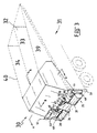
- Fig. 3 is a perspective view of a second preferred embodiment of the invention as applied to a tipping truck;
- Fig. 4 is a perspective view from one side of the dispensing apparatus of Fig. 3;
- Fig. 5 is a perspective view from the other side of the dispensing apparatus of Fig. 3;
- Fig. 6 is a cross-sectional view along A-A of Fig. 3;
- Fig. 7 is a cross-sectional view along B-B of Fig. 3 depicting the dispensing apparatus in both normal and tilted attitudes.
- the dispensing apparatus 10 of the preferred embodiment comprises a removable module 11 to which is attached a mixing discharge conveyor 12.
- the module 11 is operatively secured at the rear of a tipping trailer 13 which is illustrated in its tipped or tilted attitude.
- the module 11 includes a water tank and a cement powder tank.
- the module also provides passages or conveyor means which are gravitationally fed with bulk material such as sand and gravel 14 from the tipper trailer 13. Water and cement powder are dispensed from the module 11 at a controlled rate.
- the sand and gravel 14 is metered along with the prescribed quantities of water and cement powder into a hopper 15 of an articulated mixer discharge conveyor 12 where the predetermined quantities of the constituents of the resulting concrete mixture are mixed and finally discharged through outlet 17 directly at the construction site 18.
- An electric winch 19 may be provided to elevate the conveyor 12 from a discharge position to a transport position when the tipping trailer is in its horizontal attitude.
- the tipping trailer may be fixed to a prime mover and driven directly to the quarry to be loaded or reloaded with sand and gravel before returning to the construction site.
- the materials are transported directly from quarry to construction site without the need for intermediate storage or dispensing at a batching station.
- FIG. 2 there is illustrated in cut-away view the interior of the mixing discharge conveyor 12.
- An auger 20 having interrupted flights 21 is housed within a resilient cylindrical housing 22 of rubber or the like material.
- the interrupted flights are preferably located near the hopper 15 of the mixer 12 and serve to allow the concrete constituents to "fall back" towards hopper 15 and thereby mix further.
- Any suitable number of interruptions may be used depending on the required degree of mixing.
- the interruptions include a number of radial angled fingers 16 which in themselves are preferably adapted to convey material being mixed toward the discharge end by being angled to the transverse.
- the net effect of the interrupted flights is to provide both a "falling back" and a conveyor effect on the materials within the casing to ensure a predetermined mixing effect.
- variations in the angle to the horizontal of the mixer conveyor 12 will also allow the degree of mixing to be varied.
- the resilient casing 22 is able to resiliently deform to prevent jamming of incompressible particles such as rock particles between the auger blade and the casing. This enables the clearance between the blades and the casing to be minimised.
- Water is dispensed into the hopper 15 via a peripheral pipe 22 having a plurality of spaced outlets 23.
- Pipe 23 communicates with the water tank in module 11 via a flexible hose 24.
- Fig. 2 illustrates one form of mixer
- other mixing means may be utilised in conjunction with a dispensing apparatus according to the invention.
- the constituents may be dispensed into a horizontal mixing auger which extends the full width of the trailer tailgate and has articulated at its discharge end a spreading auger similar to the mixer of Fig. 2 but serving only to convey the mix.
- the mixer may be integral with the dispensing apparatus or independent thereof.
- conventional mixers may be used, such as the revolving bowl type agitators.
- a ramp may be employed to suitably locate the dispenser above the agitator bowl.
- one or more intermediate conveyors may be used to transmit the dispensed constituents up to the agitator bowl.
- FIG. 3 A second embodiment of the dispensing apparatus of the present invention is illustrated in Fig. 3.
- the apparatus comprises a removable module 30 operatively secured in the rear of a tipping trailer body 31 (shown in hidden detail).
- the internal structure of module 30 will be described below with reference to Figs. 4 to 7.
- the tipping trailer body includes a central partition 32 dividing the tipping body into two longitudinal storage regions 33 and 34 which communicate independently with first and second augers 35 and 36, respectively, in the dispensing apparatus.
- the augers 35 and 36 are housed inside resilient casings 37 and 38 which may be detached for cleaning purposes.
- the augers 35 and 36 serve to convey bulk material from regions 33 and 34 to a central position in the tailgate. The augers are fed gravitationally when the tipping body 31 is tipped.
- the partition 32 and side walls 39 and 40 taper upwardly toward the rear of the tipping trailer.
- a paddle wheel dispenser 41 having a plurality of radial blades 42 is rotatably mounted at the base of a cement powder tank 60 which is sandwiched between two water tanks 61, 62.
- the blades 42 include resilient edges 43 which resiliently deform as the blades contact the rigid housing 44 to sweep cement powder down the chute 45 into the central tailgate region.
- a single hydraulic motor 46 drives a common drive shaft 47 which extends across the rear of the dispenser.
- the augers 35 and 36 and the cement wheel 41 are driven from the common drive by toothed gears and chains which are housed in removable chain guards 48. The relative speeds of the augers may be changed by changing the gearing to effect a change in constituent throughput and ratio.
- outlets for the augers 35 and 36 and cement chute 45 are so positioned so that dipensed materials converge and mix to some degree prior to entering a mixer proper. In some cases the premixing will be sufficient to fully combine the dry ingredients. Powder constituents such as cement powder tend to agglomerate in a "balling" effect when wet. Hence the coalesing of dry ingredients provides a precoating of the gravel and sand prior to mixing the water.
- the cement wheel drive includes a variable speed gear box 49 which enables the ratio of cement powder to gravel and sand to be varied.
- a common drive shaft any resistance causing slowing of say, auger 35, will result in comparable slowing of auger 36 and cement wheel 41. Consequently the ratio of ingredients in the resulting mix will remain constant.
- a water outlet 50 is connectable to a flexible hose (not shown) in order to dispense water.
- a valve 51 is used to regulate flow of water and an internal flow meter reads out flow rate on the digital readout of the control panel 52.
- the control panel 52 may also include a cumulative total of material dispensed at any particular time and preferably monitors the rotations of common drive shaft 47 and is calibrated in terms of cubic measure of dispensed material.
- a further control panel 53 has switches to activate the drive and activate other operational features which will be described below.
- the module 30 is illustrated as viewed from within the partitioned regions 33 and 34 of the tipping trailer of Fig. 3.
- the module 30 includes an upper storage section 54 in which water and cement powder are separately stored.
- the lower section 55 includes a V-shaped divider 56 having a spine 57 arranged to be contiguous with the partition 32 of the tipping trailer when the module 30 is operatively secured as in Fig. 3.
- the lower wall of the upper section and the walls of the divider are convergent.
- a further convergent wall section is normally bolted or welded to flanges 58 and has its near edge secured against the inner surface of the tipping trailer walls 39 and 40.
- the present invention ensures that as gravel and sand held in the regions 33 and 34 are dispensed the augers 35 and 36 are continually fed by gravity until the regions 33 and 34 are completely empty.
- the material in regions 33 and 34 is not of a free flowing nature, it is desirable to line the deck, and in some cases the walls, with a low friction surface material such as stainless steel or polyurethane.
- a low friction surface material such as stainless steel or polyurethane.
- the sand may adhere to the deck thereby causing agglomerations of the sand to occur.
- a stainless steel deck surface in the tipping trailer minimises such adherance. It is preferable to tip the trailer to a minimum of approximately 55 degrees to the horizontal in order to optimise the dispensing of damp sand, a smaller angle being sufficient for dry sand. Other tilt angles will be appropriate for other materials.
- FIG. 6 there is illustrated a cross-sectional view through the upper storage section 54 of module 30.
- the storage section is divided into three tanks, namely a cement powder tank 60 sandwiched between two water tanks 61 and 62.
- the water tanks are linked to a common filler and also have a common outlet.
- the cement powder tank 60 is a specialised container which is of pyramidal form with walls converging to the cement wheel 41. During transportation of the dispenser compaction of the cement powder may occur and the density of the compacted cement powder may vary from around 1250 kg per cubic metre to as much as 1600 kg per cubic metre. Such variation in the density of cement powder is undesirable since the resulting mix will be of variable and unpredictable character.
- two perforated compressed air mats 65 and 66 are located across the forward and rearward internal walls of the cement powder tank. The air mats 65 and 66 are angled to prevent agglomeration of cement powder on the air mats and also direct the cement powder directly onto the blades of the cement wheel 41.
- compacted cement powder in a 1700 kg capacity tank can be fully aerated within about 1-2 minutes yielding a reproducible density of 1100 kg per cubic metre.
- the air mats 65 and 66 are supplied directly from the compressed air system of the tipping vehicle and operated from the main control panel.
- tipping illustrated in Fig. 7 at 64 is equivalent to the tipping body being at approximately 55 degrees to the horizontal.
- the central axis of the cement powder tank is substantially vertical and the tank is effectively inverted on its apex.
- Wall 67 of the tank makes approximately the same angle to the central axis as does wall 68 and the air mats direct cement powder as a vertical sheet onto the cement wheel 41.
- Section 69 is almost vertical when the dispenser is in the lowered attitude 63.
- the section 69 is therefore contiguous with main auger mounting plate 70 for simplicity of fabrication and driving the cement wheel from the common drive shaft.
- the dispenser is intended to be used as a mobile unit in a conventional tip truck
- a crane may be employed to lift the dispenser in and out of the tip truck.
- the dispenser may simply be bolted into the rear tailgate.
- the dispenser may be secured permanently in the rear of the tipping vehicle or may be manufactured integral with the body.
- the advantage of a removable dispenser is that use of the vehicle is not limited to concrete production as is the case with conventional agitators.
- the dispenser of Figs. 3 to 7 may be fitted with a mixer conveyor of the type illustrated in Fig. 2.
- a mixer conveyor of the type illustrated in Fig. 2.
- the water is gravity fed from the water tanks through two series valves. One valve is fine tuned to the desired wetness of the mix while the other valve merely serves an on-off function.
- the cumulative total of mix to be dispensed is set on the control panel, the dispenser is switched on, and the on-off water valve, which may be solenoid driven, is also opened. Water, cement powder, sand and gravel are simultaneously dispensed into the mixer.
- the water content may be fine tuned to the level desired by the concrete finisher and this setting is usually retained for the total mix with the on-off valve only being operated in response to the dispenser being switched off.
- the invention eliminates the requirement for central batching plants, and bulk materials may be loaded directly into the tipper. Furthermore the concrete is mixed on-site as required and consequently there are no problems with premature curing or the preparation of too much or too little concrete.
- the dispenser can be used to dispense asphalt.
- Asphalt is primarily a mixture of gravel, sand and hot bitumen but may include other ingredients.
- an insulated tank with internal heating elements is provided so that the hot bitumen may be dispensed at a predetermined rate along with gravel and other bulk constituents from the tip truck.
- the modified dispenser may also include a tank holding kerosene for clean down of bitumen from the unit.
- a mixer of the type illustrated in Fig. 2 may be employed.
- the tank is filled with molasses which is dispensed along with particulate bulk animal feed from the tip truck as a blending for ruminants.
- the animal feed may be dispensed to the grazing stock while the truck is moving.
Landscapes
- Preparation Of Clay, And Manufacture Of Mixtures Containing Clay Or Cement (AREA)
Claims (15)
- Dispositif transportable destiné à doser les ingrédients d'un mélange, ledit dispositif (30) pouvant être placé à l'intérieur du corps d'un conteneur mobile (31), à proximité d'une première extrémité de celui-ci, ledit dispositif (30) comportant un bac récepteur pour recevoir au moins un ingrédient provenant dudit corps de conteneur mobile (31); des premiers moyens de dosage (35, 36) associés audit bac récepteur pour distribuer ledit au moins un ingrédient avec un débit prédéterminé; un compartiment de stockage (54) pour stocker séparément au moins un autre ingrédient; et des seconds moyens de dosage (41) pour distribuer ledit au moins un autre ingrédient avec un débit prédéterminé, au moins ledit premier ingrédient et ledit au moins un autre ingrédient étant distribués par des moyens de dosage respectifs dans une zone commune pour effectuer leur mélange, lesdits premiers et seconds moyens de dosage étant mûs par un mécanisme d'entraînement commun pour maintenir un rapport constant entre lesdits ingrédients du mélange; ledit dispositif étant caractérisé en ce que ledit corps de conteneur (31) est basculable entre une position substantiellement horizontale et une position inclinée dans laquelle ladite première extrémité dudit corps de conteneur (31) est plus basse qu'une extrémité opposée de celui-ci, ledit bac récepteur recevant de ce fait ledit au moins un ingrédient provenant dudit corps de conteneur (31) sous l'effet de la gravité, ledit dispositif étant en outre caractérisé en ce que ledit compartiment de stockage (54) comprend au moins un silo à ingrédient (60) pour stocker ledit au moins un autre ingrédient dans une position surélevée par rapport auxdits seconds moyens de dosage (41) lorsque lesdits moyens formant conteneur (31) sont basculés en position lnclinée.
- Dispositif suivant la revendication 1, dans lequel ledit bac récepteur comporte au moins un passage ayant une ouverture destinée à recevoir ledit au moins un constituant provenant dudit corps de conteneur (31), une sortie communiquant avec lesdits premiers moyens de dosage (35), et des parois convergentes pour diriger ledit au moins un constituant reçu à travers ladite ouverture en direction desdits moyens de dosage (35).
- Dispositif suivant la revendication 1 ou 2, dans lequel ledit corps de conteneur (31) comprend des zones de stockage séparées (33, 34); et dans lequel ledit bac récepteur comporte des passages séparés, communiquant chacun respectivement avec une zone de stockage 34), lesdits premiers moyens de dosage comprenant des moyens de dosage (35, 36) situés à une sortie de chaque passage respectif.
- Dispositif suivant l'une ou l'autre des revendications 1 à 3, dans lequel ledit réservoir d'ingrédients (60) présente une forme pyramidale substantiellement inversée avec un axe central vertical lorsqu'il est basculé en position inclinée par ledit corps de conteneur (31), lesdits seconds moyens de dosage étant situés à l'emplacement le plus bas dudit réservoir (60) lorsqu'il est ainsi incliné.
- Dispositif suivant l'une ou l'autre des revendications 1 à 4, dans lequel il est prévu des sorties de gaz comprimé (65, 66) à l'intérieur du réservoir d'ingrédients (60), lesdites sorties de gaz comprimé (65, 66) étant situées à côté desdits seconds moyens de dosage (41).
- Dispositif suivant la revendication 5, dans lequel lesdites sorties de gaz comprimé comportent des treillis à air comprimé (65, 66) placés sur des surfaces intérieures opposées (67, 68) du réservoir d'ingrédients (60) afin de diriger ledit au moins un autre ingrédient vers la zone desdits seconds moyens de dosage (41).
- Dispositif suivant l'une ou l'autre des revendications précédentes, dans lequel il est prévu des trains d'engrenages amovibles (48) pour modifier sélectivement les rapports d'entraînement individuels respectifs desdits premiers et seconds moyens de dosage (35, 36) (41).
- Dispositif suivant l'une ou l'autre des revendications précédentes, dans lequel lesdits premiers moyens de dosage (35, 36) comprennent au moins un transporteur à vis.
- Dispositif suivant l'une ou l'autre des revendications précédentes, dans lequel lesdits seconds moyens de dosage comprennent un distributeur centrifuge à palettes (41).
- Dispositif suivant l'une ou l'autre des revendications précédentes, dans lequel lesdits moyens de stockage (54) comprennent au moins un récipient de stockage de liquide (61, 62).
- Dispositif suivant l'une ou l'autre des revendications précédentes, comportant en outre un transporteur de déchargement à mélange (12), ledit transporteur (12) comportant une trémie (15) pour recevoir des quantités dudit au moins un ingrédient et dudit au moins un autre ingrédient respectivement, dans des proportions volumétriques prédéterminées.
- Dispositif suivant la revendication 11, dans lequel le liquide provenant dudit récipient de stockage de liquide (61, 62) est ajouté dans ladite trémie (15) avec un dosage volumétrique prédéterminé.
- Dispositif suivant la revendication 12, pour la préparation de mélanges de béton ou de mortier de ciment.
- Dispositif suivant l'une ou l'autre des revendications précédentes, dans lequel ledit corps de conteneur transportable (31) comprend un corps basculant d'un véhicule basculant mobile.
- Dispositif suivant la revendication 14, dans lequel ledit dispositif transportable (30) est monté, tout en étant amovible, dans ledit véhicule basculant mobile.
Applications Claiming Priority (3)
| Application Number | Priority Date | Filing Date | Title |
|---|---|---|---|
| AUPH926586 | 1986-12-01 | ||
| AU9265/86 | 1986-12-01 | ||
| AU76106/87A AU590101B2 (en) | 1986-12-01 | 1987-07-24 | Dispensing apparatus |
Publications (2)
| Publication Number | Publication Date |
|---|---|
| EP0270202A1 EP0270202A1 (fr) | 1988-06-08 |
| EP0270202B1 true EP0270202B1 (fr) | 1991-03-27 |
Family
ID=25638133
Family Applications (1)
| Application Number | Title | Priority Date | Filing Date |
|---|---|---|---|
| EP87306661A Expired - Lifetime EP0270202B1 (fr) | 1986-12-01 | 1987-07-28 | Dispositif transportable pour le dosage des constituants d'un mélange, utilisé avec un conteneur basculant |
Country Status (1)
| Country | Link |
|---|---|
| EP (1) | EP0270202B1 (fr) |
Families Citing this family (3)
| Publication number | Priority date | Publication date | Assignee | Title |
|---|---|---|---|---|
| NL1000379C2 (nl) * | 1995-05-17 | 1996-11-19 | Arwo Bv | Houder voor het transporteren van een korrel- of poedervormig materiaal. |
| MX2022015781A (es) | 2020-06-12 | 2023-01-19 | Tirso Chavez | Aparato movil de mezcla continua. |
| CN113368994A (zh) * | 2021-06-01 | 2021-09-10 | 安徽理工大学 | 一种滤饼破碎及配比混料的装置 |
Citations (1)
| Publication number | Priority date | Publication date | Assignee | Title |
|---|---|---|---|---|
| SU757359A1 (ru) * | 1977-11-09 | 1980-08-23 | Vasilij Romanov | Устройство для перемешивания и перегрузки грузов 1 |
Family Cites Families (5)
| Publication number | Priority date | Publication date | Assignee | Title |
|---|---|---|---|---|
| FR2222844A5 (en) * | 1973-03-22 | 1974-10-18 | Courbon Claude Marie | Continuous supply concrete batcher-mixer - constituents gravitate from hoppers to mixer-chute via ladder belt |
| US4219279A (en) * | 1979-03-26 | 1980-08-26 | Haws Paul M | Mobile gunnite material mixer |
| DE3419997A1 (de) * | 1984-02-24 | 1985-08-29 | Johannes 3531 Borgentreich Götte | Futtermischwagen |
| US4538916A (en) * | 1984-06-20 | 1985-09-03 | Zimmerman Harold M | Motor mounting arrangement on a mixing auger |
| US4624575A (en) * | 1985-08-30 | 1986-11-25 | Lantz Construction Company | Cement mobile mixer |
-
1987
- 1987-07-28 EP EP87306661A patent/EP0270202B1/fr not_active Expired - Lifetime
Patent Citations (1)
| Publication number | Priority date | Publication date | Assignee | Title |
|---|---|---|---|---|
| SU757359A1 (ru) * | 1977-11-09 | 1980-08-23 | Vasilij Romanov | Устройство для перемешивания и перегрузки грузов 1 |
Also Published As
| Publication number | Publication date |
|---|---|
| EP0270202A1 (fr) | 1988-06-08 |
Similar Documents
| Publication | Publication Date | Title |
|---|---|---|
| US6007233A (en) | Mobile concrete mixing and delivery system | |
| US3917236A (en) | Concrete mixing plant | |
| US3310293A (en) | Concrete mixing and delivery system | |
| US5203628A (en) | Portable batch mixing apparatus for cementitious construction materials | |
| US5785420A (en) | Apparatus for metering and mixing aggregate and cement | |
| US4855960A (en) | Process and apparatus for the preparation of mortars | |
| US4810097A (en) | Dispensing apparatus | |
| US3905586A (en) | Mini-plant for batching and mixing materials | |
| US20040218462A1 (en) | Concrete delivery system | |
| US3179272A (en) | Apparatus for transporting and dispensing finely divided solid materials | |
| US4219279A (en) | Mobile gunnite material mixer | |
| EP2155456B1 (fr) | Appareil de mélange mobile | |
| EP0270202B1 (fr) | Dispositif transportable pour le dosage des constituants d'un mélange, utilisé avec un conteneur basculant | |
| US3197075A (en) | Variable volume auger assembly | |
| US5653567A (en) | Mobile cattle feeder | |
| US3073606A (en) | Method of mixing and spreading fertilizer | |
| US3072388A (en) | Feeding and mixing apparatus for concrete guns or the like | |
| US5375925A (en) | Material blender mixer and method therefor | |
| IE881498L (en) | Producing animal feed | |
| GB2344296A (en) | Vehicle comprising apparatus for making foamed concrete | |
| RU1806060C (ru) | Устройство дл транспортировани и смешивани ингредиентов смесей | |
| EP0305150A2 (fr) | Appareil mobile pour mélanger du béton | |
| AU2024235744A1 (en) | Blending particulate material | |
| US3468519A (en) | Silage and feed grain mixing and conveying system | |
| AU707096B2 (en) | Mobile concrete mixing and delivery system |
Legal Events
| Date | Code | Title | Description |
|---|---|---|---|
| PUAI | Public reference made under article 153(3) epc to a published international application that has entered the european phase |
Free format text: ORIGINAL CODE: 0009012 |
|
| 17P | Request for examination filed |
Effective date: 19871231 |
|
| AK | Designated contracting states |
Kind code of ref document: A1 Designated state(s): DE GB IT NL |
|
| 17Q | First examination report despatched |
Effective date: 19890419 |
|
| GRAA | (expected) grant |
Free format text: ORIGINAL CODE: 0009210 |
|
| ITF | It: translation for a ep patent filed | ||
| AK | Designated contracting states |
Kind code of ref document: B1 Designated state(s): DE GB IT NL |
|
| REF | Corresponds to: |
Ref document number: 3768921 Country of ref document: DE Date of ref document: 19910502 |
|
| PLBE | No opposition filed within time limit |
Free format text: ORIGINAL CODE: 0009261 |
|
| STAA | Information on the status of an ep patent application or granted ep patent |
Free format text: STATUS: NO OPPOSITION FILED WITHIN TIME LIMIT |
|
| 26N | No opposition filed | ||
| REG | Reference to a national code |
Ref country code: GB Ref legal event code: IF02 |
|
| PGFP | Annual fee paid to national office [announced via postgrant information from national office to epo] |
Ref country code: IT Payment date: 20060731 Year of fee payment: 20 |
|
| PGFP | Annual fee paid to national office [announced via postgrant information from national office to epo] |
Ref country code: NL Payment date: 20060926 Year of fee payment: 20 |
|
| PGFP | Annual fee paid to national office [announced via postgrant information from national office to epo] |
Ref country code: DE Payment date: 20060927 Year of fee payment: 20 |
|
| PGFP | Annual fee paid to national office [announced via postgrant information from national office to epo] |
Ref country code: GB Payment date: 20060928 Year of fee payment: 20 |
|
| PG25 | Lapsed in a contracting state [announced via postgrant information from national office to epo] |
Ref country code: NL Free format text: LAPSE BECAUSE OF EXPIRATION OF PROTECTION Effective date: 20070728 |
|
| REG | Reference to a national code |
Ref country code: GB Ref legal event code: PE20 |
|
| NLV7 | Nl: ceased due to reaching the maximum lifetime of a patent |
Effective date: 20070728 |
|
| PG25 | Lapsed in a contracting state [announced via postgrant information from national office to epo] |
Ref country code: GB Free format text: LAPSE BECAUSE OF EXPIRATION OF PROTECTION Effective date: 20070727 |