EP0270404B1 - Anordnung magnetischer Pole, Anwendung in einem Schreib/Lese-Magnetkopf und Herstellungsverfahren - Google Patents
Anordnung magnetischer Pole, Anwendung in einem Schreib/Lese-Magnetkopf und Herstellungsverfahren Download PDFInfo
- Publication number
- EP0270404B1 EP0270404B1 EP87402430A EP87402430A EP0270404B1 EP 0270404 B1 EP0270404 B1 EP 0270404B1 EP 87402430 A EP87402430 A EP 87402430A EP 87402430 A EP87402430 A EP 87402430A EP 0270404 B1 EP0270404 B1 EP 0270404B1
- Authority
- EP
- European Patent Office
- Prior art keywords
- magnetic
- face
- layer
- pole
- substrate
- Prior art date
- Legal status (The legal status is an assumption and is not a legal conclusion. Google has not performed a legal analysis and makes no representation as to the accuracy of the status listed.)
- Expired - Lifetime
Links
- 238000004519 manufacturing process Methods 0.000 title claims description 8
- 239000000758 substrate Substances 0.000 claims description 26
- 239000000696 magnetic material Substances 0.000 claims description 17
- 238000005520 cutting process Methods 0.000 claims description 7
- 230000006698 induction Effects 0.000 claims description 7
- 239000000463 material Substances 0.000 claims description 7
- 238000000034 method Methods 0.000 claims description 7
- 238000000151 deposition Methods 0.000 claims description 6
- 238000003754 machining Methods 0.000 claims description 5
- 238000005498 polishing Methods 0.000 claims description 5
- 239000004020 conductor Substances 0.000 description 4
- 239000010409 thin film Substances 0.000 description 4
- 238000005516 engineering process Methods 0.000 description 3
- 238000004804 winding Methods 0.000 description 3
- 229910000859 α-Fe Inorganic materials 0.000 description 3
- 230000000740 bleeding effect Effects 0.000 description 2
- 230000008021 deposition Effects 0.000 description 2
- 230000007547 defect Effects 0.000 description 1
- 230000000694 effects Effects 0.000 description 1
- 239000011521 glass Substances 0.000 description 1
- 230000010354 integration Effects 0.000 description 1
- 238000003801 milling Methods 0.000 description 1
- 230000004048 modification Effects 0.000 description 1
- 238000012986 modification Methods 0.000 description 1
- 230000000284 resting effect Effects 0.000 description 1
Images



Classifications
-
- G—PHYSICS
- G11—INFORMATION STORAGE
- G11B—INFORMATION STORAGE BASED ON RELATIVE MOVEMENT BETWEEN RECORD CARRIER AND TRANSDUCER
- G11B5/00—Recording by magnetisation or demagnetisation of a record carrier; Reproducing by magnetic means; Record carriers therefor
- G11B5/127—Structure or manufacture of heads, e.g. inductive
- G11B5/31—Structure or manufacture of heads, e.g. inductive using thin films
- G11B5/3163—Fabrication methods or processes specially adapted for a particular head structure, e.g. using base layers for electroplating, using functional layers for masking, using energy or particle beams for shaping the structure or modifying the properties of the basic layers
-
- G—PHYSICS
- G11—INFORMATION STORAGE
- G11B—INFORMATION STORAGE BASED ON RELATIVE MOVEMENT BETWEEN RECORD CARRIER AND TRANSDUCER
- G11B5/00—Recording by magnetisation or demagnetisation of a record carrier; Reproducing by magnetic means; Record carriers therefor
- G11B5/127—Structure or manufacture of heads, e.g. inductive
- G11B5/31—Structure or manufacture of heads, e.g. inductive using thin films
- G11B5/3109—Details
- G11B5/3116—Shaping of layers, poles or gaps for improving the form of the electrical signal transduced, e.g. for shielding, contour effect, equalizing, side flux fringing, cross talk reduction between heads or between heads and information tracks
-
- G—PHYSICS
- G11—INFORMATION STORAGE
- G11B—INFORMATION STORAGE BASED ON RELATIVE MOVEMENT BETWEEN RECORD CARRIER AND TRANSDUCER
- G11B5/00—Recording by magnetisation or demagnetisation of a record carrier; Reproducing by magnetic means; Record carriers therefor
- G11B5/127—Structure or manufacture of heads, e.g. inductive
- G11B5/31—Structure or manufacture of heads, e.g. inductive using thin films
- G11B5/3176—Structure of heads comprising at least in the transducing gap regions two magnetic thin films disposed respectively at both sides of the gaps
- G11B5/3179—Structure of heads comprising at least in the transducing gap regions two magnetic thin films disposed respectively at both sides of the gaps the films being mainly disposed in parallel planes
- G11B5/3183—Structure of heads comprising at least in the transducing gap regions two magnetic thin films disposed respectively at both sides of the gaps the films being mainly disposed in parallel planes intersecting the gap plane, e.g. "horizontal head structure"
Definitions
- the invention relates to an arrangement of magnetic poles for recording / reading head in thin layers, its application to a magnetic head and its production method.
- the air gap of the magnetic head is produced by superposition of magnetic layers constituting the first magnetic pole, of a non-magnetic layer constituting the air gap proper, finally of a another succession of magnetic layers constituting the second pole.
- the whole is engraved so as to define the height of the air gap corresponding to the track width. After sawing, this air gap is polished so as to adjust the depth of the air gap.
- the many types of thin film heads differ in the nature of the substrates, superstrate and layers used, as well as the embodiment of the winding. However, the embodiment of the air gap is always identical to that mentioned above.
- the air gap depth adjustment operation is individual and very delicate. Indeed, this depth must not exceed ten microns at the risk of lowering the efficiency of the head too much.
- the sawing operation itself offers an inaccuracy of several tens of microns.
- the known technology of magnetic thin film heads therefore mainly encounters a polishing phase individual head which is very expensive and has a low success rate.
- Thin film magnetic heads are known as described in documents JP-A-55 132 519 and US-A-4 399 479, the poles of which are produced in thin layers on a substrate and in which the active surface of the head is parallel to the substrate.
- the realization of the air gap of such a head can present difficulties.
- the document JP-A-61 151 818 describes a magnetic head in thin layers in which a support part, in which a conductor is inserted, supports on the same face first and second magnetic poles in thin layers separated by a layer air gap made of non-magnetic material, this layer of non-magnetic material extending between the second magnetic pole and the support part and its conductor.
- document JP-A-61 151 818 explains that the first pole is produced on the support part and on the conductor. A sidewall of this pole is machined, so as to guarantee the straightness of the air gap, by mechanical machining (using a milling cutter for example). This machining plans to start the upper face of the conductor above which the air gap will be made. We thus make a bleeding at the location of what will be the air gap. Then, a layer of non-magnetic material is deposited on the assembly (for the air gap) then a layer of magnetic material (for the second pole). Finally, the upper face of the assembly is machined so as to remove the layer of magnetic material and the layer of non-magnetic material located above the first pole.
- the disadvantage of such a head is that, near the air gap, the surface on which the non-magnetic layer and consequently the magnetic layer is produced, has a groove. This bleeding, on the scale of the layers produced in thin layers constitutes a significant surface irregularity. This irregularity locally leads to a modification of the magnetic properties of the magnetic layer of the second pole or even failures in this layer. These defects are all the more important when they exist near the air gap of the magnetic head. Indeed, a magnetic head in thin layers has an air gap of a few tenths of a micrometer thick. Under these conditions, a variation in the magnetic properties of the layer or a failure located near the air gap will behave like an additional air gap: it will disturb the functioning of the head and may possibly write itself on the information medium.
- the invention proposes a solution which makes it possible to resolve this difficulty.
- the invention provides for integrating the polishing phase in the operations prior to sawing the substrate, thereby reducing its cost in a ratio close to the level of integration of the heads on the substrate which can reach the rate of 1000.
- the type of head produced is more efficient than the heads according to the prior art.
- This head comprises a substrate part or support part 1 having a planar face 10.
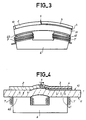
- This face 10 may be only essentially planar and have, as shown in FIG. 3, a radius of curvature which is very large relative to the thickness of the air gap. Indeed, in the context of the previously mentioned thin film technology (French Patent Application No. 86 05238 already cited), a thickness of a few tenths of a micrometer for the air gap layer is negligible compared to the radius of curvature of the face 10 and leads to consider that the face 10 is essentially flat around the air gap.
- This flat face 10 carries a first magnetic head pole 2 which has a flank 20 forming an angle with the plane of the face 10. According to the embodiment shown in FIG. 1, the flank 20 is substantially perpendicular to the plane of the face 10.
- the face 10 also carries a layer 4 of a non-magnetic material which covers the flank 20 of the first pole 2.
- the layer 4 carries a second pole 3 of which a flank 30 is substantially perpendicular to the plane of the face 10 and parallel flank 20.
- the sides 20 and 30 define an air gap 5 between the poles 2 and 3.
- the upper faces of the poles 2 and 3 and of the non-magnetic layer 4 are at the same level at least at the location of the air gap 5.
- a magnetic support, not shown, placed in front of this air gap 5 will allow the two poles to be magnetically connected and the magnetic circuit of the head to be closed.
- Figure 2 shows in section view the head of Figure 1.
- the support part 1 is made of material non-magnetic such as glass and its thickness is small such that a magnetic field of recording or reading passes through it without too much loss.
- the ends 60 and 61 are respectively placed of a magnetic circuit 6.
- coils d 'magnetic field induction 7 and 7' near the ends 60 and 61.
- These coils induce a magnetic field which circulates through the poles 2 and 3 according to the arrows O indicated in Figure 2.
- a support magnetic a magnetic strip for example, which would be placed on the upper surface of poles 2 and 3, would magnetically couple the two poles above the air gap.
- the head shown in FIG. 2 therefore constitutes a magnetic recording / reading head.
- the upper face of the head is flat. As shown in Figure 3, and as mentioned above, it can be curved convex.
- the support part 1 is curved, in particular its face 10.
- the poles 2 and 3, and the non-magnetic layer 4 are produced on this face 10 and therefore have a curved shape. It should be noted that the ends 60 and 61 of the magnetic circuit 6 must be curved to adapt to the shape of the part 1.
- Such a head is more particularly usable in recording / reading devices with magnetic tapes where the tape can be better pressed against the head.
- the curvature of the head can be limited to a region surrounding the air gap 5.
- the support part 1 is curved only in a small region and the magnetic circuit 6 can be designed so that its ends 60 and 61, adapt to flat parts of the part 1, which facilitates the production of the circuit 6.
- FIGS. 5 to 9 an example of a production method according to the invention of a magnetic head such as that of FIG. 1 will be described.
- a layer of a magnetic material is deposited on one face 10 of a substrate 1 and then a cut is made in this layer, a magnetic pole 2 having at least one side 20 that is substantially perpendicular on the face 10 of the substrate 1.
- a layer of a non-magnetic material 4 is deposited.
- a layer of a magnetic material is deposited followed by a cut in this layer of a magnetic pole 3 having a side 30 facing it with side 20 of pole 2.
- machining is carried out followed by polishing, the effect of which is to remove the insulating layer located on the magnetic pole 2 and to level off the two poles 2 and 3 at the two flanks 20 and 30 which determine the air gap of the magnetic head as shown in FIG. 1.
- the part of the layer 4 of non-magnetic material located on the face 10 of the substrate 1 is connected with the part of this layer 4 situated on the side 20 at an obtuse angle.
- the method of the invention allows the production of several heads, thus described, on the same substrate.
- a fifth step of cutting heads thus produced collectively is provided.
- pairs of windings such as 7-7 ′ are produced, molded from a non-magnetic material. These coils 7-7 ′ are produced at the same pitch as the magnetic poles 2-3 so that they can be matched to each other.
- the magnetic circuits 6 are then produced from a material such as ferrite. These magnetic circuits have pairs of pads 60, 60 ′ at the same pitch as the magnetic coils so that each pair of coils can be associated with a pair of pads.
- the substrate plate 1 carrying the magnetic poles 2,3 is then associated, as shown in FIG. 10, with the set of coils and with the magnetic ferrite circuits 6 so that each pair of poles 2,3 is associated a pair of 7.7 ′ windings and a pair of 60.60 ′ ferrite studs.
- the fifth step mentioned above provides for individualizing each magnetic head by cutting along the dashed lines shown on the right in FIG. 10.
Landscapes
- Engineering & Computer Science (AREA)
- Manufacturing & Machinery (AREA)
- Magnetic Heads (AREA)
- Magnetic Record Carriers (AREA)
Claims (6)
- Anordnung von Magnetpolen für einen magnetischen Dünnschicht-Schreib/Lesekopf, wobei die Anordnung enthält:- ein Substrat (1), das eine parallel zur aktiven Seite des Magnetkopfes liegende Hauptseite (10) besitzt,- einen ersten Pol des Magnetkreises (2) auf dieser Hauptseite (10), der eine erste, einen Winkel mit der Hauptseite (10) bildende Flanke (20) aufweist,- einen zweiten Pol des Magnetkreises (3), der auf der Hauptseite (10) sitzt und eine zweite, zur ersten Flanke (20) im wesentlichen parallele Flanke (30) aufweist,- eine Schicht (4) aus unmagnetischem Material zwischen der ersten Flanke (20) und der zweiten Flanke (30), wobei diese Schicht sich zwischen dem zweiten Pol (3) und der Hauptseite (10) verlängert,dadurch gekennzeichnet, daß die Schicht (4) aus unmagnetischem Material als einzige Unregelmäßigkeit die durch den Anschluß des Bereichs der Schicht (4), der sich auf der im wesentlichen ebenen Hauptseite befindet, und dem Bereich der Schicht (4), der sich auf der ersten Flanke (20) des ersten Pols (2) befindet, gebildete Unregelmäßigkeit besitzt und daß der gesamte Raum zwischen der Hauptseite (10) und dem zweiten Pol (3) von der unmagnetischen Schicht (4) besetzt ist.
- Anordnung von Magnetpolen nach Anspruch 1, dadurch gekennzeichnet, daß die Hauptseite (10) des Substrats (1) in Höhe des Magnetspalts (5) konvex gekrümmt ist.
- Magnetkopf, der die Anordnung nach einem der Ansprüche 1 bis 2 anwendet, dadurch gekennzeichnet, daß das Substrat (1) aus unmagnetischem Material ist, und daß auf einer der Hauptseite (10) des Substrats gegenüberliegenden zweiten Seite (11) zwei Enden (60, 61) eines Magnetfeldinduktionskreises (6) liegen, der mindestens eine Magnetfeldinduktionsspule (7, 7′) trägt, wobei jedes dieser Enden (60, 61) gegenüber einem der Pole (2, 3) liegt.
- Verfahren zur Herstellung einer Anordnung von Magnetpolen für einen Dünnschicht-Magnetkopf gemäß einem der vorhergehenden Ansprüche, dadurch gekennzeichnet, daß es die nachstehenden Verfahrensschritt in Folge aufweist;- a) einen ersten Verfahrensschritt, bei dem auf einer im wesentlichen ebenen Oberseite eines Substrats (1) ein erster Magnetpol (2) mit einer einen Winkel mit der Hauptseite (10) des Substrats (1) einschließenden Flanke (20) aufgebracht und ausgeschnitten wird,- b) einen zweiten Verfahrensschritt, bei dem auf die Oberseite des Substrats (1) und den ersten Magnetpol (2) eine Schicht aus unmagnetischem Material (4) aufgebracht wird,- c) einen dritten Verfahrensschritt, bei dem auf die Schicht (4) aus unmagnetischem Material ein zweiter Magnetpol (3) aufgebracht und ausgeschnitten wird, der mit einem Bereich die Flanke (20) des ersten Pols überlappt,- d) einen vierten Verfahrensschritt, in dem die Schicht aus unmagnetischem Material (4) und des zweiten Magnetpols (3) so spanend bearbeitet und poliert wird, daß die aktive Seite des Magnetkopfes parallel zur Hauptseite des Substrats (1) entsteht.
- Herstellungsverfahren nach Anspruch 4, dadurch gekennzeichnet, daß während der vier ersten Verfahrensschritte mehrere Anordnungen von Magnetpolen auf einem gemeinsamen Substrat hergestellt werden und daß in einem fünften Verfahrensschritt mindestens eine Anordnung von Magnetpolen abgeschnitten wird.
- Herstellungsverfahren für einen Magnetkopf nach Anspruch 5, dadurch gekennzeichnet, daß zwischen dem vierten Verfahrensschritt und dem fünften Verfahrensschritt eine erste Phase der Herstellung von Magnetfeldinduktionsspulen, die in ein unmagnetisches Material eingegossen werden, eine zweite Phase der Herstellung von Magnetkreisen, eine dritte Phase des Zusammenbaus der Induktionsspulen, der Magnetkreise und der Anordnungen von Magnetpolen eingefügt wird, wobei der fünfte Verfahrensschritt im Zerschneiden des so erhaltenen Aufbaus besteht.
Priority Applications (1)
| Application Number | Priority Date | Filing Date | Title |
|---|---|---|---|
| EP94201146A EP0618568B1 (de) | 1986-10-28 | 1987-10-28 | Dünnschicht-Aufnahme-Wiedergabemagnetkopf und Herstellungsverfahren |
Applications Claiming Priority (2)
| Application Number | Priority Date | Filing Date | Title |
|---|---|---|---|
| FR8614974A FR2605783B1 (fr) | 1986-10-28 | 1986-10-28 | T ete magnetique d'enregistrement/lecture en couches minces et son procede de realisation |
| FR8614974 | 1986-10-28 |
Related Child Applications (2)
| Application Number | Title | Priority Date | Filing Date |
|---|---|---|---|
| EP94201146A Division EP0618568B1 (de) | 1986-10-28 | 1987-10-28 | Dünnschicht-Aufnahme-Wiedergabemagnetkopf und Herstellungsverfahren |
| EP94201146.1 Division-Into | 1987-10-28 |
Publications (2)
| Publication Number | Publication Date |
|---|---|
| EP0270404A1 EP0270404A1 (de) | 1988-06-08 |
| EP0270404B1 true EP0270404B1 (de) | 1994-09-28 |
Family
ID=9340272
Family Applications (2)
| Application Number | Title | Priority Date | Filing Date |
|---|---|---|---|
| EP94201146A Expired - Lifetime EP0618568B1 (de) | 1986-10-28 | 1987-10-28 | Dünnschicht-Aufnahme-Wiedergabemagnetkopf und Herstellungsverfahren |
| EP87402430A Expired - Lifetime EP0270404B1 (de) | 1986-10-28 | 1987-10-28 | Anordnung magnetischer Pole, Anwendung in einem Schreib/Lese-Magnetkopf und Herstellungsverfahren |
Family Applications Before (1)
| Application Number | Title | Priority Date | Filing Date |
|---|---|---|---|
| EP94201146A Expired - Lifetime EP0618568B1 (de) | 1986-10-28 | 1987-10-28 | Dünnschicht-Aufnahme-Wiedergabemagnetkopf und Herstellungsverfahren |
Country Status (7)
| Country | Link |
|---|---|
| US (1) | US4942490A (de) |
| EP (2) | EP0618568B1 (de) |
| JP (1) | JP2935365B2 (de) |
| DE (2) | DE3752246T2 (de) |
| ES (2) | ES2127880T3 (de) |
| FR (1) | FR2605783B1 (de) |
| WO (1) | WO1988003307A1 (de) |
Families Citing this family (32)
| Publication number | Priority date | Publication date | Assignee | Title |
|---|---|---|---|---|
| US4912584A (en) * | 1988-03-09 | 1990-03-27 | Digital Equipment Corporation | Method for fabricating magnetic recording poles |
| FR2639137B1 (fr) * | 1988-11-15 | 1990-12-21 | Thomson Csf | Tete magnetique a entrefer saturable et dispositif matriciel comportant un ensemble de telles tetes |
| FR2640070A1 (fr) * | 1988-12-06 | 1990-06-08 | Thomson Csf | Tete magnetique planaire d'enregistrement ´ lecture et procede de realisation |
| FR2648940B1 (fr) * | 1989-06-27 | 1991-09-06 | Thomson Csf | Procede de realisation de tete magnetique multipiste et tete magnetique multipiste |
| US5189580A (en) * | 1989-06-30 | 1993-02-23 | Ampex Corporation | Ultra small track width thin film magnetic transducer |
| FR2649526B1 (fr) * | 1989-07-04 | 1991-09-20 | Thomson Csf | Procede de fabrication de tetes magnetiques planaires par alveolage d'une plaquette non magnetique, et tetes magnetiques obtenues par un tel procede |
| FR2652670B1 (fr) * | 1989-10-03 | 1995-06-23 | Thomson Csf | Tete de lecture magnetooptique a haute resolution. |
| JP3200060B2 (ja) * | 1990-09-12 | 2001-08-20 | ソニー株式会社 | 薄膜磁気ヘッド |
| FR2723242B1 (fr) * | 1994-07-26 | 1996-08-30 | Thomson Csf | Tete magnetique a element saturable et dispositif matriciel comportant un ensemble de tetes magnetiques |
| US5754377A (en) * | 1994-08-26 | 1998-05-19 | Aiwa Research And Development, Inc. | Thin film magnetic head including an elevated gap structure |
| US5490028A (en) * | 1994-08-26 | 1996-02-06 | Aiwa Research And Development, Inc. | Thin film magnetic head including an integral layered shield structure |
| US5801909A (en) * | 1994-08-26 | 1998-09-01 | Aiwa Research And Development, Inc. | Thin film magnetic head including durable wear layer and non-magnetic gap structures |
| US6091581A (en) * | 1994-08-26 | 2000-07-18 | Aiwa Co., Ltd. | Thin film magnetic head including a separately deposited diamond-like carbon gap structure and magnetic control wells |
| US5748417A (en) * | 1994-08-26 | 1998-05-05 | Aiwa Research And Development, Inc. | Thin film magnetic head including layered magnetic side poles |
| US5544774A (en) * | 1994-08-26 | 1996-08-13 | Aiwa Research And Development, Inc. | Method of eliminating pole recession in a thin film magnetic head |
| US5563754A (en) * | 1994-08-26 | 1996-10-08 | Aiwa Research And Development, Inc. | Thin film magnetic head including a durable wear layer and gap structure |
| US5909346A (en) * | 1994-08-26 | 1999-06-01 | Aiwa Research & Development, Inc. | Thin magnetic film including multiple geometry gap structures on a common substrate |
| US5673474A (en) * | 1994-08-26 | 1997-10-07 | Aiwa Research And Development, Inc. | Method of fabricating a thin film magnetic head including layered magnetic side poles |
| JPH08171712A (ja) * | 1994-08-26 | 1996-07-02 | Aiwa Co Ltd | 側面露出型薄膜磁気ヘッド並びにその製造方法 |
| FR2727555B1 (fr) | 1994-11-25 | 1996-12-20 | Thomson Csf | Tete magnetique d'enregistrement/lecture et son procede de realisation |
| FR2727556B1 (fr) * | 1994-11-29 | 1997-01-03 | Thomson Csf | Procede de realisation d'une tete magnetique d'enregistrement/lecture et tete d'enregistrement/lecture |
| US5621594A (en) * | 1995-02-17 | 1997-04-15 | Aiwa Research And Development, Inc. | Electroplated thin film conductor coil assembly |
| FR2738657B1 (fr) * | 1995-09-12 | 1997-10-03 | Thomson Csf | Tete magnetique d'enregistrement/lecture |
| US5926350A (en) * | 1996-03-15 | 1999-07-20 | International Business Machines Corporation | Dual gap horizontal thin film inductive head |
| US6069015A (en) * | 1996-05-20 | 2000-05-30 | Aiwa Research And Development, Inc. | Method of fabricating thin film magnetic head including durable wear layer and non-magnetic gap structure |
| KR100264802B1 (ko) | 1998-02-24 | 2000-09-01 | 윤종용 | 플래너구조 박막자기헤드의 갭 형성방법 |
| FR2786345B1 (fr) | 1998-11-24 | 2001-02-09 | Thomson Csf | Dispositif de cryptage quantique |
| US7130152B1 (en) | 1999-04-01 | 2006-10-31 | Storage Technology Corporation | High track density magnetic recording head |
| FR2797514B3 (fr) | 1999-08-10 | 2001-10-12 | Thomson Csf | Dispositif de lecture magneto-optique pour bandes magnetiques multipistes |
| US7149173B2 (en) * | 2000-10-17 | 2006-12-12 | Thales | Medium for recording optically readable data, method for making same and optical system reproducing said data |
| FR2824905B1 (fr) * | 2001-05-15 | 2003-08-29 | Thomson Csf | Gyrometre a fibre optique |
| US6650496B2 (en) | 2001-05-15 | 2003-11-18 | Phs Mems | Fully integrated matrix magnetic recording head with independent control |
Family Cites Families (19)
| Publication number | Priority date | Publication date | Assignee | Title |
|---|---|---|---|---|
| US3214645A (en) * | 1960-05-09 | 1965-10-26 | Minnesota Mining & Mfg | Transducer poles |
| US3478341A (en) * | 1966-07-11 | 1969-11-11 | Ncr Co | Random access magnetic disc storage device with peripheral bearing means |
| US3601871A (en) * | 1968-09-30 | 1971-08-31 | Texas Instruments Inc | Method for fabricating magnetic read-write head array and product |
| DE2819208C2 (de) * | 1978-05-02 | 1984-10-31 | Siemens AG, 1000 Berlin und 8000 München | Mehrfach-Dünnschicht-Magnetkopf zur Bandaufzeichnung von Hochfrequenzsignalen |
| JPS5573913A (en) * | 1978-11-30 | 1980-06-04 | Victor Co Of Japan Ltd | Magnetic head |
| JPS55132519A (en) * | 1979-04-03 | 1980-10-15 | Fujitsu Ltd | Manufacture for thin film magnetic head |
| JPS5683823A (en) * | 1979-12-11 | 1981-07-08 | Fujitsu Ltd | Production for horizontal thin film magnetic head |
| JPS56145517A (en) * | 1980-04-14 | 1981-11-12 | Fujitsu Ltd | Thin-film magnetic head |
| US4399479A (en) * | 1981-02-04 | 1983-08-16 | Eastman Kodak Company | Thin film magnetic head having good low frequency response |
| JPS57141009A (en) * | 1981-02-23 | 1982-09-01 | Hitachi Ltd | Thin film magnetic head and its production |
| JPS5853019A (ja) * | 1981-09-25 | 1983-03-29 | Hitachi Ltd | 磁気ヘツドの製造方法 |
| JPS5930227A (ja) * | 1982-08-10 | 1984-02-17 | Matsushita Electric Ind Co Ltd | 磁気ヘツドの製造方法 |
| JPS60121508A (ja) * | 1983-12-05 | 1985-06-29 | Yokogawa Hokushin Electric Corp | 磁気ヘッド装置およびその製造方法 |
| JPS60150219A (ja) * | 1984-01-18 | 1985-08-07 | Hitachi Ltd | 薄膜磁気ヘツドの製造方法 |
| JPS60191407A (ja) * | 1984-03-12 | 1985-09-28 | Hitachi Ltd | 磁気ヘツド |
| JPS615404A (ja) * | 1984-06-18 | 1986-01-11 | Matsushita Electric Ind Co Ltd | 垂直磁化型磁気ヘツド |
| JPS6139206A (ja) * | 1984-07-28 | 1986-02-25 | Hitachi Ltd | 磁気ヘツド装置 |
| JPS6139914A (ja) * | 1984-07-31 | 1986-02-26 | Konishiroku Photo Ind Co Ltd | 磁気ヘツド |
| JPS61151818A (ja) * | 1984-12-26 | 1986-07-10 | Hitachi Ltd | 薄膜磁気ヘツド |
-
1986
- 1986-10-28 FR FR8614974A patent/FR2605783B1/fr not_active Expired - Lifetime
-
1987
- 1987-10-28 JP JP62506790A patent/JP2935365B2/ja not_active Expired - Lifetime
- 1987-10-28 ES ES94201146T patent/ES2127880T3/es not_active Expired - Lifetime
- 1987-10-28 US US07/221,455 patent/US4942490A/en not_active Expired - Lifetime
- 1987-10-28 WO PCT/FR1987/000424 patent/WO1988003307A1/fr not_active Ceased
- 1987-10-28 DE DE3752246T patent/DE3752246T2/de not_active Expired - Lifetime
- 1987-10-28 DE DE3750607T patent/DE3750607T2/de not_active Expired - Lifetime
- 1987-10-28 EP EP94201146A patent/EP0618568B1/de not_active Expired - Lifetime
- 1987-10-28 ES ES87402430T patent/ES2060605T3/es not_active Expired - Lifetime
- 1987-10-28 EP EP87402430A patent/EP0270404B1/de not_active Expired - Lifetime
Also Published As
| Publication number | Publication date |
|---|---|
| US4942490A (en) | 1990-07-17 |
| DE3750607D1 (de) | 1994-11-03 |
| EP0618568A3 (de) | 1995-05-10 |
| JPH01501105A (ja) | 1989-04-13 |
| ES2060605T3 (es) | 1994-12-01 |
| JP2935365B2 (ja) | 1999-08-16 |
| FR2605783B1 (fr) | 1992-05-15 |
| EP0270404A1 (de) | 1988-06-08 |
| FR2605783A1 (fr) | 1988-04-29 |
| DE3752246T2 (de) | 1999-06-17 |
| EP0618568B1 (de) | 1998-12-23 |
| DE3750607T2 (de) | 1995-01-19 |
| ES2127880T3 (es) | 1999-05-01 |
| EP0618568A2 (de) | 1994-10-05 |
| DE3752246D1 (de) | 1999-02-04 |
| WO1988003307A1 (fr) | 1988-05-05 |
Similar Documents
| Publication | Publication Date | Title |
|---|---|---|
| EP0270404B1 (de) | Anordnung magnetischer Pole, Anwendung in einem Schreib/Lese-Magnetkopf und Herstellungsverfahren | |
| EP0407244B1 (de) | Herstellungsverfahren von planaren Magnetköpfen durch Wabenstrukturierung von nicht-magnetischen Platten und nach diesem Verfahren erhaltene Magnetköpfe | |
| EP0284495B1 (de) | Magnetkopf zum Lesen von Spuren mit sehr schmaler Breite und Herstellungverfahren | |
| EP0337879A1 (de) | Vorrichtung zum Schreiben auf und Lesen von einem magnetischen Träger und Herstellungsverfahren | |
| EP0420755B1 (de) | Herstellungsverfahren eines Magnetaufzeichnungskopfes und nach diesem Verfahren erhaltener Kopf | |
| EP0406362B1 (de) | Herstellungsverfahren eines aufnahme-/wiedergabekopfes und nach diesem verfahren erhaltener kopf | |
| EP0188944A1 (de) | System für senkrechte Aufzeichnung und Verfahren zur Herstellung eines Magnetkopfes | |
| EP0152328B1 (de) | Vorrichtung zum Schreiben auf und Lesen von einem magnetischen Träger und Herstellungsverfahren | |
| FR2741470A1 (fr) | Procede de realisation d'une tete magnetique planaire et tete obtenue par ce procede | |
| EP0880774B1 (de) | Senkrechter magnetkopf mit integrierter spule und herstellungsverfahren | |
| FR2661030A1 (fr) | Tete magnetique d'enregistrement/lecture et procedes de realisation. | |
| EP0800160B1 (de) | Herstellungsverfahren für einen Doppel-Magnetkopf mit entgegengesetzten Azimuth-Spalten | |
| EP0040994A1 (de) | Magnetwandler, der einen Spalt mit veränderbarer Grössen-Dimension aufweist, zur Wiedergabe oder zum Aufzeichnen von Informationen eines magnetischen Trägers | |
| EP0338063B1 (de) | Aufzeichnungs-wiedergabemagnetkopf und verfahren zu seiner herstellung | |
| FR2723242A1 (fr) | Tete magnetique a element saturable et dispositif matriciel comportant un ensemble de tetes magnetiques | |
| FR2781916A1 (fr) | Procede de realisation collective de tetes magnetiques integrees a surface portante obtenue par photolithographie | |
| EP0416994A1 (de) | Herstellungsverfahren eines Magnetkopfes mit passend orientierter Achse mit leichter Magnetisierung und nach diesem Verfahren hergestellter Kopf | |
| FR2877484A1 (fr) | Dispositif d'enregistrement et/ou de lecture a tetes magnetiques multiples a entrefers azimutes | |
| FR2508216A1 (fr) | Tete magnetique pour ecriture, lecture et effacement sur piste magnetique etroite, et procede de fabrication de cette tete magnetique, simple ou multipiste | |
| FR2802011A1 (fr) | Tete de lecture planaire a element magneto-resistif | |
| FR2877485A1 (fr) | Dispositif d'enregistrement et/ou de lecture a tetes magnetiques multiples azimutees | |
| FR2622340A1 (fr) | Procede de realisation d'une tete magnetique d'enregistrement/lecture et tete realisee selon ce procede | |
| FR2570862A1 (fr) | Procede de fabrication de tetes magnetiques a tres petits entrefers et tetes magnetiques obtenues par un tel procede | |
| JPH04172607A (ja) | 磁気ヘッド | |
| FR2553220A1 (fr) | Tete magnetique multipiste perfectionnee et procede de fabrication |
Legal Events
| Date | Code | Title | Description |
|---|---|---|---|
| PUAI | Public reference made under article 153(3) epc to a published international application that has entered the european phase |
Free format text: ORIGINAL CODE: 0009012 |
|
| AK | Designated contracting states |
Kind code of ref document: A1 Designated state(s): DE ES GB IT NL |
|
| 17P | Request for examination filed |
Effective date: 19880622 |
|
| RAP3 | Party data changed (applicant data changed or rights of an application transferred) |
Owner name: THOMSON-CSF |
|
| 17Q | First examination report despatched |
Effective date: 19900208 |
|
| RAP1 | Party data changed (applicant data changed or rights of an application transferred) |
Owner name: THOMSON-CSF |
|
| GRAA | (expected) grant |
Free format text: ORIGINAL CODE: 0009210 |
|
| AK | Designated contracting states |
Kind code of ref document: B1 Designated state(s): DE ES GB IT NL |
|
| ITF | It: translation for a ep patent filed | ||
| REF | Corresponds to: |
Ref document number: 3750607 Country of ref document: DE Date of ref document: 19941103 |
|
| REG | Reference to a national code |
Ref country code: ES Ref legal event code: FG2A Ref document number: 2060605 Country of ref document: ES Kind code of ref document: T3 |
|
| GBT | Gb: translation of ep patent filed (gb section 77(6)(a)/1977) |
Effective date: 19941115 |
|
| PLBE | No opposition filed within time limit |
Free format text: ORIGINAL CODE: 0009261 |
|
| STAA | Information on the status of an ep patent application or granted ep patent |
Free format text: STATUS: NO OPPOSITION FILED WITHIN TIME LIMIT |
|
| 26N | No opposition filed | ||
| REG | Reference to a national code |
Ref country code: GB Ref legal event code: IF02 |
|
| PGFP | Annual fee paid to national office [announced via postgrant information from national office to epo] |
Ref country code: NL Payment date: 20061003 Year of fee payment: 20 |
|
| PGFP | Annual fee paid to national office [announced via postgrant information from national office to epo] |
Ref country code: GB Payment date: 20061025 Year of fee payment: 20 |
|
| PGFP | Annual fee paid to national office [announced via postgrant information from national office to epo] |
Ref country code: DE Payment date: 20061026 Year of fee payment: 20 |
|
| PGFP | Annual fee paid to national office [announced via postgrant information from national office to epo] |
Ref country code: IT Payment date: 20061031 Year of fee payment: 20 |
|
| PGFP | Annual fee paid to national office [announced via postgrant information from national office to epo] |
Ref country code: ES Payment date: 20061124 Year of fee payment: 20 |
|
| REG | Reference to a national code |
Ref country code: GB Ref legal event code: PE20 |
|
| NLV7 | Nl: ceased due to reaching the maximum lifetime of a patent |
Effective date: 20071028 |
|
| REG | Reference to a national code |
Ref country code: ES Ref legal event code: FD2A Effective date: 20071029 |
|
| PG25 | Lapsed in a contracting state [announced via postgrant information from national office to epo] |
Ref country code: NL Free format text: LAPSE BECAUSE OF EXPIRATION OF PROTECTION Effective date: 20071028 |
|
| PG25 | Lapsed in a contracting state [announced via postgrant information from national office to epo] |
Ref country code: GB Free format text: LAPSE BECAUSE OF EXPIRATION OF PROTECTION Effective date: 20071027 Ref country code: ES Free format text: LAPSE BECAUSE OF EXPIRATION OF PROTECTION Effective date: 20071029 |