EP0270463B1 - Hydraulische oder pneumatische Antriebseinheit, deren bewegliches Translationselement gegen Drehung um seine Längsachse gesichert ist - Google Patents
Hydraulische oder pneumatische Antriebseinheit, deren bewegliches Translationselement gegen Drehung um seine Längsachse gesichert ist Download PDFInfo
- Publication number
- EP0270463B1 EP0270463B1 EP19870402757 EP87402757A EP0270463B1 EP 0270463 B1 EP0270463 B1 EP 0270463B1 EP 19870402757 EP19870402757 EP 19870402757 EP 87402757 A EP87402757 A EP 87402757A EP 0270463 B1 EP0270463 B1 EP 0270463B1
- Authority
- EP
- European Patent Office
- Prior art keywords
- rod
- guiding
- piston
- cylinder
- rigid
- Prior art date
- Legal status (The legal status is an assumption and is not a legal conclusion. Google has not performed a legal analysis and makes no representation as to the accuracy of the status listed.)
- Expired - Lifetime
Links
- 239000007787 solid Substances 0.000 description 3
- 239000012530 fluid Substances 0.000 description 2
- 238000006073 displacement reaction Methods 0.000 description 1
- 210000000056 organ Anatomy 0.000 description 1
- 238000007789 sealing Methods 0.000 description 1
Images
Classifications
-
- F—MECHANICAL ENGINEERING; LIGHTING; HEATING; WEAPONS; BLASTING
- F15—FLUID-PRESSURE ACTUATORS; HYDRAULICS OR PNEUMATICS IN GENERAL
- F15B—SYSTEMS ACTING BY MEANS OF FLUIDS IN GENERAL; FLUID-PRESSURE ACTUATORS, e.g. SERVOMOTORS; DETAILS OF FLUID-PRESSURE SYSTEMS, NOT OTHERWISE PROVIDED FOR
- F15B15/00—Fluid-actuated devices for displacing a member from one position to another; Gearing associated therewith
- F15B15/08—Characterised by the construction of the motor unit
- F15B15/14—Characterised by the construction of the motor unit of the straight-cylinder type
- F15B15/1414—Characterised by the construction of the motor unit of the straight-cylinder type with non-rotatable piston
Definitions
- Known hydraulic or pneumatic cylinders comprise a control rod which is integral with a piston mounted sliding in a cylinder, the ends of which are fitted with closing elements.
- the piston separates in the cylinder an annular chamber closed by the closing element, said first element, which is crossed by the rod, from a solid chamber closed by the other closing element, said second element.
- the movable element in translation constituted by the rod and its piston is free to rotate about its axis.
- the point of the member to be moved or blocked, on which the thrust of the jack is applied must be centered on the axis of the piston rod. Otherwise, since it can rotate around its geometric axis, the contact of this point with the end of the rod is not established in the same place on each actuation.
- this end of the rod has an asymmetrical or eccentric tip to escape an obstacle placed on the path or to adapt to a particular shape taken by the organ to be moved or blocked, it is essential the piston rod of the actuating cylinder cannot rotate around its geometric axis.
- German application number 1,952,677 describes a jack whose control rod carrying the piston is immobilized in rotation about the axis of the cylinder in which this piston is mounted to slide.
- the control rod delimits an internal conduit in which coaxially extends a rigid bar fixed to the bottom of the cylinder and passing through a ring integral with the rod.
- the bar has a square section and then comprises four guide surfaces against which the four facets of a square central orifice which the ring delimits are in contact.
- the jack comprises the combination of means taught by the aforementioned German application, combination according to which a control rod is guided through a first end element for closing a cylinder and is integral with a piston mounted to slide in this cylinder, the piston separating in said cylinder an annular chamber closed by the first closing element, from a solid chamber closed by a second closing element, which forms a body with a rigid longitudinal element extending in a duct delimited by the rod and opening into the full chamber, the rigid longitudinal element having at least one guide surface parallel to the axis of the rod and cooperating with at least one bearing element carried by said rod and disposed in contact with said surface (s) guide.
- the guide surface or surfaces of the rigid longitudinal element of the aforesaid jack cooperates with at least one support element of revolution passing through the duct in a direction substantially orthogonal to the axis of the control rod and carried by the latter to be in linear contact with the said surface (s).
- the rigid guide element is a flat bar of substantially rectangular section, the two guide surfaces of which are parallel to each other cooperate with at least two fixed pins passing through the control rod and brought into contact by the one of their generators with said surfaces.
- the rigid guide element is a flat bar of substantially rectangular section, the two guide surfaces of which are parallel to each other cooperate with at least two rotating needles, the ends of each needle being mounted rotating in bearings. of the rod and the intermediate part of the needle considered being brought into contact by one of its generatrices with the corresponding guide surface.
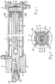
- the jack comprises a cylinder 1, the ends of which are nested with sealing, in a first and a second element 2 and 3 constituted respectively by a thick tubular part and a bottom; the part 2 is connected to the bottom 3 by tie rods 32 extending along the cylinder 1 so that these various components 1 to 3 form a rigid monolithic assembly resistant to any internal pressure.
- a piston 4 equipped with a gasket 5.
- the piston 4 is integral with a control rod 6; for this purpose, it has, from a shoulder 7, an extreme centering 8 extended by a thread 9, so that the reamed and tapped piston can be centered and screwed until it abuts against the shoulder, this which ensures precise fixing.
- the control rod 6 passes through a guide bore 10 that the part 2 delimits and, to ensure the seal, seals 11 are provided.
- the piston 4 separates in the cylinder 1 an annular chamber 12 closed off by the part 2, from a solid chamber 13 closed off by the bottom 3.
- open conduits 14 and 15 delimited respectively by the part 2 and the bottom 3, conduits which are selectively connected by a distributor to a source of pressurized hydraulic or pneumatic fluid.
- the rod 6 moves in the direction of the arrow F, following an actuating stroke or in the opposite direction following an erasing stroke.
- the movable assembly constituted by the piston 4 and the rod 6 is caused to move in translation and at the same time it is free to rotate around the geometric axis of the cylinder 1.
- a rigid bar 16 is fixed by one of its ends in the bottom 3, for example by being embedded in a housing 17 and maintained therein by means of a pin 18
- the bar 16 extends in a blind conduit 19 which delimits the rod 6.
- the conduit 19 is coaxial and the bar 16 has two parallel flat guide surfaces 20 and 21 extending symmetrically with respect to the axis of the conduit 19 and therefore of the rod 6. Furthermore, these two surfaces 20 and 21 cooperate by contact with two pins 22 and 23 forcefully engaged transversely in the end of said rod.
- a single guide surface for example 20, is sufficient and then cooperates with a transverse support element, 22 consequently.
- the corresponding transverse support element can be rotatable instead of being fixed and constituted for example by a needle whose ends are fitted in bearings force-fitted into the end of the rod 6.
- the guide surface or each of the guide surfaces of the element 16 can cooperate with two or more support elements instead of just one.
- the free end of the rod 6 is adapted to the member to be actuated and its environment.
- a nozzle 24 equipped with an eccentric pad 25 is mounted and immobilized by any suitable means in this free end of the rod 6.
- the pad 25 can also be shaped, whether it is eccentric or not, in correspondence with a housing for the member to be actuated.
Landscapes
- Engineering & Computer Science (AREA)
- Physics & Mathematics (AREA)
- Fluid Mechanics (AREA)
- Mechanical Engineering (AREA)
- General Engineering & Computer Science (AREA)
- Actuator (AREA)
Claims (4)
Applications Claiming Priority (2)
| Application Number | Priority Date | Filing Date | Title |
|---|---|---|---|
| FR8617089 | 1986-12-05 | ||
| FR8617089A FR2607877B1 (fr) | 1986-12-05 | 1986-12-05 | Verin hydraulique ou pneumatique dont l'element mobile en translation est immobilise en rotation autour de son axe longitudinal |
Publications (2)
| Publication Number | Publication Date |
|---|---|
| EP0270463A1 EP0270463A1 (de) | 1988-06-08 |
| EP0270463B1 true EP0270463B1 (de) | 1990-01-03 |
Family
ID=9341632
Family Applications (1)
| Application Number | Title | Priority Date | Filing Date |
|---|---|---|---|
| EP19870402757 Expired - Lifetime EP0270463B1 (de) | 1986-12-05 | 1987-12-04 | Hydraulische oder pneumatische Antriebseinheit, deren bewegliches Translationselement gegen Drehung um seine Längsachse gesichert ist |
Country Status (3)
| Country | Link |
|---|---|
| EP (1) | EP0270463B1 (de) |
| ES (1) | ES2013303B3 (de) |
| FR (1) | FR2607877B1 (de) |
Cited By (1)
| Publication number | Priority date | Publication date | Assignee | Title |
|---|---|---|---|---|
| CN104454756A (zh) * | 2014-09-26 | 2015-03-25 | 凌长清 | 一种自回程柱塞式液压缸 |
Families Citing this family (6)
| Publication number | Priority date | Publication date | Assignee | Title |
|---|---|---|---|---|
| FR2635361B1 (fr) * | 1988-08-10 | 1993-06-11 | Cit Alcatel | Verin a commande par fluide a course lineaire et bras coulissant bloque en rotation |
| GB2274323B (en) * | 1993-01-14 | 1995-04-05 | Ian Musson | Fluid cylinders |
| IT237848Y1 (it) * | 1997-08-04 | 2000-09-29 | Waircom M B S S P A | Cilindrico pneumatico con albero non rotante |
| FR2820089B1 (fr) * | 2001-01-26 | 2005-11-25 | Gaussin Sa | Dispositif de roulement pour vehicule de transport de charges lourdes |
| CN102927083B (zh) * | 2012-11-27 | 2015-04-01 | 东风汽车公司 | 一种气缸活塞限位装置 |
| CN115899010A (zh) * | 2022-12-16 | 2023-04-04 | 厦门银华机械有限公司 | 一种液压油缸中防止活塞杆与缸筒相对转动的限位结构 |
Family Cites Families (2)
| Publication number | Priority date | Publication date | Assignee | Title |
|---|---|---|---|---|
| GB1243792A (en) * | 1968-08-05 | 1971-08-25 | Steelweld Ltd | Improvements in and relating to fluid-operated piston and cylinder devices |
| DE1952677A1 (de) * | 1969-10-20 | 1971-04-29 | Buchmann Rudolf Ch | Vorrichtung zur Verhinderung einer unkontrollierten Drehbewegung bei Kolben und Kolbenstangen an hydraulischen oder pneumatischen Geraeten |
-
1986
- 1986-12-05 FR FR8617089A patent/FR2607877B1/fr not_active Expired - Fee Related
-
1987
- 1987-12-04 ES ES87402757T patent/ES2013303B3/es not_active Expired - Lifetime
- 1987-12-04 EP EP19870402757 patent/EP0270463B1/de not_active Expired - Lifetime
Cited By (1)
| Publication number | Priority date | Publication date | Assignee | Title |
|---|---|---|---|---|
| CN104454756A (zh) * | 2014-09-26 | 2015-03-25 | 凌长清 | 一种自回程柱塞式液压缸 |
Also Published As
| Publication number | Publication date |
|---|---|
| FR2607877B1 (fr) | 1993-02-12 |
| EP0270463A1 (de) | 1988-06-08 |
| ES2013303B3 (es) | 1990-05-01 |
| FR2607877A1 (fr) | 1988-06-10 |
Similar Documents
| Publication | Publication Date | Title |
|---|---|---|
| EP0187729B1 (de) | Kugelhahn | |
| BE1006434A3 (fr) | Commande d'au moins deux bras de stabilisation dans un dispositif de forage ou de carottage. | |
| FR2517790A1 (fr) | Valve a levee equipee d'un soufflet entre l'obturateur et le corps, notamment pour fluides radioactifs ou toxiques | |
| FR2528144A1 (fr) | Dispositif d'etancheite pour robinet a tournant spherique | |
| FR2810701A1 (fr) | Verin hydraulique a double effet avec dispositif de blocage axial | |
| FR2748298A1 (fr) | Dispositif de verin pneumatique | |
| EP0150643B1 (de) | Sicherheitsventil, insbesondere zum Schliessen einer Erdölbohrung | |
| EP0457700B1 (de) | Kupplungsvorrichtung mit drehbaren Küken für Rohrleitungen | |
| EP0021977A1 (de) | Hydraulischer Verteiler, insbesondere für Servosteuerungen in Flugzeugen und Helikoptern | |
| EP0270463A1 (de) | Hydraulische oder pneumatische Antriebseinheit, deren bewegliches Translationselement gegen Drehung um seine Längsachse gesichert ist | |
| FR2947318A1 (fr) | Vanne a obturateur pour un dispositif d'accouplement de conduits | |
| FR2674042A1 (fr) | Dispositif hydraulique et pneumatique de blocage. | |
| EP0190528A1 (de) | Pneumatische oder hydraulische Stelleinrichtung | |
| EP0306416A1 (de) | Pilot-gesteuertes Sicherheitsventil | |
| CH341952A (fr) | Dispositif d'évacuation pour moule utilisé dans une machine à fonte sous pression | |
| BE897518A (fr) | Soupape de securite pilotee | |
| FR2578619A1 (fr) | Vanne de securite pour puits, capable de resister a des temperatures elevees | |
| FR2495976A1 (fr) | Perfectionnement aux tours a poupee centrale | |
| FR2685750A1 (fr) | Vanne a joint retractable a double elasticite. | |
| EP1591742B1 (de) | Rückstossbremse | |
| FR2510710A1 (fr) | Dispositif de fin de course pour directions hydrauliques assistees | |
| FR2647208A1 (fr) | Dispositif doseur d'un liquide contenu dans une premiere chambre et a transferer par petites doses dans un fluide s'ecoulant dans une deuxieme chambre | |
| LU86439A1 (fr) | Robinet pour gaz comprimes ou liquefies | |
| CH374289A (fr) | Distributeur pour fluide sous pression | |
| FR2596140A1 (fr) | Dispositif pour le remplissage de recipients sous pression particulierement de bouteilles avec robinet a volant |
Legal Events
| Date | Code | Title | Description |
|---|---|---|---|
| PUAI | Public reference made under article 153(3) epc to a published international application that has entered the european phase |
Free format text: ORIGINAL CODE: 0009012 |
|
| AK | Designated contracting states |
Kind code of ref document: A1 Designated state(s): ES IT |
|
| 17P | Request for examination filed |
Effective date: 19881121 |
|
| 17Q | First examination report despatched |
Effective date: 19890323 |
|
| GRAA | (expected) grant |
Free format text: ORIGINAL CODE: 0009210 |
|
| AK | Designated contracting states |
Kind code of ref document: B1 Designated state(s): ES IT |
|
| ITF | It: translation for a ep patent filed | ||
| PLBE | No opposition filed within time limit |
Free format text: ORIGINAL CODE: 0009261 |
|
| STAA | Information on the status of an ep patent application or granted ep patent |
Free format text: STATUS: NO OPPOSITION FILED WITHIN TIME LIMIT |
|
| 26N | No opposition filed | ||
| ITTA | It: last paid annual fee | ||
| PGFP | Annual fee paid to national office [announced via postgrant information from national office to epo] |
Ref country code: ES Payment date: 19931220 Year of fee payment: 7 |
|
| PG25 | Lapsed in a contracting state [announced via postgrant information from national office to epo] |
Ref country code: ES Free format text: LAPSE BECAUSE OF THE APPLICANT RENOUNCES Effective date: 19941205 |
|
| REG | Reference to a national code |
Ref country code: ES Ref legal event code: FD2A Effective date: 20010402 |
|
| PG25 | Lapsed in a contracting state [announced via postgrant information from national office to epo] |
Ref country code: IT Free format text: LAPSE BECAUSE OF NON-PAYMENT OF DUE FEES;WARNING: LAPSES OF ITALIAN PATENTS WITH EFFECTIVE DATE BEFORE 2007 MAY HAVE OCCURRED AT ANY TIME BEFORE 2007. THE CORRECT EFFECTIVE DATE MAY BE DIFFERENT FROM THE ONE RECORDED. Effective date: 20051204 |