EP0270464A1 - Gegenmassnahmeverfahren beim Bestimmen von Zielen und Lasertelemetrie, Materialien und Vorrichtungen dazu - Google Patents
Gegenmassnahmeverfahren beim Bestimmen von Zielen und Lasertelemetrie, Materialien und Vorrichtungen dazu Download PDFInfo
- Publication number
- EP0270464A1 EP0270464A1 EP87402762A EP87402762A EP0270464A1 EP 0270464 A1 EP0270464 A1 EP 0270464A1 EP 87402762 A EP87402762 A EP 87402762A EP 87402762 A EP87402762 A EP 87402762A EP 0270464 A1 EP0270464 A1 EP 0270464A1
- Authority
- EP
- European Patent Office
- Prior art keywords
- doped material
- wavelength
- radiation
- doped
- machine
- Prior art date
- Legal status (The legal status is an assumption and is not a legal conclusion. Google has not performed a legal analysis and makes no representation as to the accuracy of the status listed.)
- Withdrawn
Links
Images
Classifications
-
- G—PHYSICS
- G01—MEASURING; TESTING
- G01S—RADIO DIRECTION-FINDING; RADIO NAVIGATION; DETERMINING DISTANCE OR VELOCITY BY USE OF RADIO WAVES; LOCATING OR PRESENCE-DETECTING BY USE OF THE REFLECTION OR RERADIATION OF RADIO WAVES; ANALOGOUS ARRANGEMENTS USING OTHER WAVES
- G01S7/00—Details of systems according to groups G01S13/00, G01S15/00, G01S17/00
- G01S7/48—Details of systems according to groups G01S13/00, G01S15/00, G01S17/00 of systems according to group G01S17/00
- G01S7/495—Counter-measures or counter-counter-measures using electronic or electro-optical means
-
- C—CHEMISTRY; METALLURGY
- C09—DYES; PAINTS; POLISHES; NATURAL RESINS; ADHESIVES; COMPOSITIONS NOT OTHERWISE PROVIDED FOR; APPLICATIONS OF MATERIALS NOT OTHERWISE PROVIDED FOR
- C09K—MATERIALS FOR MISCELLANEOUS APPLICATIONS, NOT PROVIDED FOR ELSEWHERE
- C09K11/00—Luminescent materials, e.g. electroluminescent or chemiluminescent
- C09K11/06—Luminescent materials, e.g. electroluminescent or chemiluminescent containing organic luminescent materials
-
- F—MECHANICAL ENGINEERING; LIGHTING; HEATING; WEAPONS; BLASTING
- F41—WEAPONS
- F41H—ARMOUR; ARMOURED TURRETS; ARMOURED OR ARMED VEHICLES; MEANS OF ATTACK OR DEFENCE, e.g. CAMOUFLAGE, IN GENERAL
- F41H3/00—Camouflage, i.e. means or methods for concealment or disguise
Definitions
- the present invention relates to a countermeasure method in the field of objective designation and laser telemetry, as well as the materials for the implementation of this method.
- a laser in particular of the YAG (Neodymium) type with a wavelength of 1.06 micrometers
- the general principle consists in directing on the target, using an illuminator, a laser beam of known characteristics and in studying the characteristics of the radiation returned by said target.
- the illuminator laser beam can be either continuous or pulsed.
- the return beam is studied according to known techniques, such as interferometry, doppler effect, measurement of time offset of the pulse. This measurement makes it possible to know the distance from the target as well as, in certain cases, the speed and the direction of movement.
- This information is essential for guiding a weapon such as a missile.
- the illuminator can be embedded on the projectile or be fixed on a weapon system transmitting information to the projectile by electromagnetic waves or by wire guidance.
- the target can be constituted by a land, sea or air vehicle.
- countermeasures In the state of the art, only few countermeasures are known which make it possible to disturb laser telemetry.
- Sometimes used "decoys" intended to return a signal not conforming to the characteristics of the target.
- this principle is difficult to implement for laser radiation and has only a very low efficiency due to progress in the field of signal discrimination allowing the rejection of information deemed aberrant by the weapon system.
- French patent application 85 09189 of the present applicant proposed to disturb the transmission of electromagnetic radiation produced by a source in a band of predetermined wavelength and intended to be received by a signal detection receiver, by interposition of a screen absorbing at least part of the radiation emitted in the wavelength band.
- the present invention relates to a countermeasure method allowing a machine to substantially reduce the radiation it re-emits when it is lit by a laser beam illuminator, as well as the materials for the implementation of said method.
- the method according to the present invention consists in covering at least part of the machine with a material absorbing at least partially the laser radiation used for telemetry or the designation of objective, and in re-emitting it in a wavelength band diffusely different.
- Said method consists in particular in covering at least part of the machine with a material absorbing at least partially the radiation with a wavelength of 1.06 micrometers, such as that usually emitted by YAG laser illuminators, and in re-emit it in the form of diffuse radiation of different wavelength.
- This re-emission radiation is neither monochromatic nor coherent.
- the energy re-emitted for a wavelength of 1.06 micrometers is therefore very greatly attenuated, and, as a result, the operation of the laser rangefinder will be deeply disturbed.
- the absorption wavelength is fixed at 10.6 micrometers.
- the re-emission wavelength will be chosen so as to correspond to a spectral absorption band of the atmosphere.
- the atmosphere has, in effect, on the ground, a transmission spectrum comprising certain holes coming from the absorption ranges of its constituents, essentially carbon dioxide, water vapor, oxygen and ozone.
- the main absorption wavelength bands are substantially equal to: - 1.96 to 1.8 micrometers - 1.45 to 1.3 micrometers - 1.15 to 1.12 micrometers - 0.96 to 0.93 micrometers - 0.83 to 0.80 micrometers 0.76 to 0.75 micrometers
- part of the re-emitted radiation is detected with a view to an alarm.
- the presence of re-emission radiation means that the device is subject to laser telemetry. It is therefore possible to detect the presence of said retransmission signal in order to alert the pilot of the machine, or to modify the behavior of an automatic machine.
- the present invention also relates to materials for implementing the countermeasure method.
- This material advantageously consists of an organic matrix doped with at least one photoluminescent material.
- said matrix consists of a doped resin.
- This resin is deposited on the machine by coating, in the form of paint or varnish.
- the choice of resin depends on the type of machine and its conditions of use. Mention may be made, by way of nonlimiting example, of resins of the polyurethane, acrylic, polyvinyl acetate, silicone type, formolurea resins, polymethyl methyl acrylate. These resins will preferably be chosen or treated so as to have a low electrical conductivity to reduce the radar response. They can also be deposited in the form of a film with a thickness of a few tenths of a millimeter. In addition, the resin will have the characteristics of durability, resistance and presentation required by the environment in which said machine operates: sea, air, water, land.
- Doping can be carried out according to known techniques by dispersing photoluminescent dopants in the liquid resin or by grafting. It can also be carried out by introducing doped particles into a matrix of the organic resin type. The doped particles are produced in the form of fibers forming one of the components of a composite material. In this case, the dopant photoluminescent is introduced in dispersion into the material of a glass fiber, a mineral fiber or an organic fiber.
- the photoluminescent dopant is of the type having an absorption peak for a wavelength of 1.06 micrometers and a re-emission peak for a wavelength other than 1.06 micrometers, and preferably included in a spectral region d absorption of the atmosphere.
- optically active components of the type - 4 (7 (2 phenyl 4H-1-benzothiopyran-4-ylidene) 4 bromo-3-5-trimethylene-1,3,5-heptatrienyl) 2 phenyl-1-benzothiopyrylium perchlorate. - 3-3 ⁇ -diethyl-9-11-15-17-dineopentethylene thiopentacarbocyanin perchlorate. - Compounds of the coronene graphite C24 H12 type, or more generally polycyclic aromatic hydrocarbons.
- One of the photoluminescent compounds whose re-emission band is located upstream gives the material good transmission in the visible spectrum and limits visible reflections, and the other whose re-emission band is located downstream of the re-emission band of the main photoluminescent compound makes it possible to adapt the re-emission wavelength band to the spectral sensitivity of a photodetector or to a band of weak light transmission from the atmosphere.
- the I.R. radiation is reemitted by the varnish in a diffuse manner, in particular in the direction of the photosensitive detector.
- the detection of re-emission radiation makes it possible to constitute an alarm. This detection will be carried out at several points on the machine, so as to supplement the alarm with an indicator of the direction of the laser illuminator.
- the doped material forms a rigid transparent canopy in the visible spectrum.
- a canopy is especially intended for an aircraft or a helicopter.
- the material constituting the canopy is composed of a matrix of the polymethyl methyl acrylate (PMMA) type, of an epoxy resin, of alkyd, of furanic copolymers or of ecopolymers of known type.
- PMMA polymethyl methyl acrylate
- said canopy is divided into sectors for identifying the direction of the laser illuminator.
- said sectors can be, for example, three in number, the normal to the first sector being oriented towards the front of the helicopter, the normal to the other two sectors respectively to the right and to the left of the craft.
- At least one photosensitive detector is associated with each of these sectors.
- a laser radiation of wavelength of 1.06 micrometers When directed on the machine, it is absorbed by the photoluminescent material of one of the sectors and re-emitted in the form of diffuse radiation of different wavelength . This re-emitted radiation is detected by a sensitive photodetector in the re-emitting wavelength band.
- the identification of the radiation incidence sector provides an indication of the origin of the telemetry radiation, and therefore of the location of the illuminator. Detection of re-emission radiation may give rise to an audible or visual alarm.
- the photodetector can be chosen of the junction type and can be fitted with a low bandwidth filter centered on the material re-emission wavelengths.
- the photodetector is followed by an electronic processing chain making it possible to eliminate the background noise.
- Said processing chain may in particular comprise a front detector making it possible to signal the incidence of a laser pulse, as well as a servo system making it possible to eliminate the effects of variation in ambient lighting.
- This servo system can be implemented in a simple manner by a WHEASTON bridge comprising in one of the branches a junction photodetector provided with a filter whose passband is centered on the re-emission wavelength, and in the 'other branch a photodetector of the same kind comprising another filter eliminating the band of wavelength of retransmission.
- the alarm can be supplemented by a threat indicator by sectors or a text-to-speech system.
- said canopy constitutes a detection volume.
- This detection volume can be produced in the form of a half sphere placed on the sides of a machine, or under the belly of an aircraft.
- Said half detection sphere comprises identification sectors made of a doped material each provided with at least one photodetector.
- the doped rigid transparent material constitutes a helmet visor.
- the visor In addition to its role of countermeasure and alarm when said visor is capable of a photodetector, it avoids dazzling or burns of the pilot's retina thanks to the conversion of the incident laser beam into radiation with spectral and spatial diffusion. important.
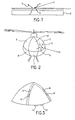
- the doped material (1) is deposited on at least part of the outer surface (2) of a machine, in the form of a film a few tenths of a millimeter thick. This deposition can be carried out by all known techniques, and in particular in the form of paint, varnish or adhesive film.
- the doped material (1) is optically active. It absorbs the incident beam (3), for example from a laser illuminator. This 1.06 micrometer wavelength beam is absorbed by the doped material (1) and is re-emitted in the form of diffuse radiation (4). This diffusion is both spatial and spectral, the spectral band of re-emission of the doped material (1) excited by an incident radiation of determined wavelength being in the form of a relatively narrow peak centered on a different wavelength of 1.06 micrometers.
- one or more other photoluminescent materials can be introduced so as to form a light cascade.
- the first photoluminescent material is chosen so as to absorb radiation of 1.06 micrometers, and to re-emit radiation of a first determined wavelength
- the second photoluminescent material is chosen so as to absorbing radiation of said first determined wavelength and re-emitting radiation of another wavelength.
- the volume concentration of the photoluminescent materials is between 0.0001% to 0.01%.
- the doped material forms particles which can be introduced into one of the constituents of the outer surfaces of the machine. They may have the form of fibers intended for the production of composite materials, or flakes of various shapes intended to be introduced into a varnish.
- the matrix will consist of resins of the type: - polyurethane, - acrylic, - silicone, - ethyl vinyl acetate (EVA), - polymethyl methyl acrylate, - formalin-urea resin, - acrylovinyl copolymers, - polyethylene copolymers, - polyethylene-polystyrene copolymers, - polymethyl methyl acrylate-EVA-polystyrene copolymers, - acrylovinyl copolymers, - polyethylene-EVA copolymers, - EVA acrylic copolymers.
- the material constitutes a transparent canopy.
- the matrix advantageously consists of polymethyl methyl acrylate.
- FIG. 2 schematically represents a helicopter provided with a canopy of the type of the invention.
- the canopy (5) is transparent, and can be divided into several sectors (6), (7), (8), (9), (10) and (11).
- the different sectors are interconnected by a rigid reinforcement of known type.
- each sector is provided with photosensitive detectors (12) arranged on the edges.
- the re-emission radiation is transmitted to said photodetectors (12) by a waveguide effect.
- an incident beam (13) is directed on the machine, it is intercepted by one of the sectors.
- Said incident beam (13) is absorbed by the doped material of the sector and is re-emitted in the form of diffuse radiation of different wavelength, which is detected by the photosensitive detectors (12) arranged along said sector.
- the photosensitive detectors (12) are known type photodetectors, and are made up of junction photodetectors.
- the photodetectors (12) are provided with a narrow bandpass filter intended to eliminate all the radiation other than that corresponding to the re-emission wavelength, in order to reduce the background noise. The measurement will be made by an amplifier circuit of known type. However, it is possible to further reduce the background noise coming essentially from the hot parts of the craft, such as engines, turbines, on-board electronic systems, or from the heating of the air on the fuselage of
- each sector there is at the edge of each sector at least one other photodetector (14) whose spectral sensitivity is different. Its role is to cancel variations due to changes in ambient brightness.
- the photosensitive detectors (12) and (14) can be mounted in two branches of a bridge of the WHEASTON bridge type. Said bridge is followed by a processing chain comprising in particular a discriminator, an edge detector, and a visual or audible indicator.
- the visual indicator can be produced in the form of a series of indicator lights of the light-emitting diode type indicating on a schematic representation of the machine, the sector illuminated by an incident beam coming from a laser illuminator. This visual indicator can be supplemented by an audible alarm or a text-to-speech alarm.
- the transparent material comprising a series of photodetectors produces a helmet visor.
- this visor absorbs laser radiation and prevents the pilot from being dazzled or injured by the cornea.
- the applicant has produced a semi sphere of composite material covered with a varnish consisting of a PMMA matrix doped with an optically active component of type 4 (7 (2 phenyl 4H-1-benzothiopyran-4-ylidene) 4 bromo-3-5-trimethylene 1-3-5-heptatrienyl) 2 phenyl-1 -benzothiopyrylium, at a concentration of 10% by volume.
- the material thus produced has an absorption band centered on a wavelength of 1.06 micrometers and a re-emission band, the maximum of which is between 1.12 and 1.15 micrometers.
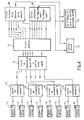
- the semi-sphere with a diameter of approximately 15 cm, is divided into four equal sectors. Each of these sectors comprises two photodetectors (12) whose sensitivity is maximum for a wavelength between 1.12 and 1.15 micrometers. These photodetectors are connected to signal processing circuits (15) intended to eliminate background noise and spurious signals.
- An I.R. signal holding and signal shaping circuit (16) analyzes the signals corresponding to each of the sectors and stores them in digital form thanks to a memory circuit (17).
- the information thus stored is analyzed by a threat direction analyzer circuit (18) and an "approaching or distancing" analyzer circuit (19), then transmitted to the pilot in visual form using a visual indicator. (20) fixed on the dashboard, or introduced into the on-board computer, as well as in voice form by a voice alarm (21).
- a varnish is produced by dispersing a coronene in an EVA type matrix, the concentration of the coronene being 10 exp -3.
Landscapes
- Engineering & Computer Science (AREA)
- Chemical & Material Sciences (AREA)
- Materials Engineering (AREA)
- Organic Chemistry (AREA)
- General Engineering & Computer Science (AREA)
- Computer Networks & Wireless Communication (AREA)
- Physics & Mathematics (AREA)
- General Physics & Mathematics (AREA)
- Radar, Positioning & Navigation (AREA)
- Remote Sensing (AREA)
- Optical Radar Systems And Details Thereof (AREA)
- Photometry And Measurement Of Optical Pulse Characteristics (AREA)
Applications Claiming Priority (2)
| Application Number | Priority Date | Filing Date | Title |
|---|---|---|---|
| FR8616976A FR2607936B1 (fr) | 1986-12-04 | 1986-12-04 | Procede de contre-mesure dans le domaine de la designation d'objectifs et de la telemetrie laser, materiaux et dispositifs pour la mise en oeuvre dudit procede de contre-mesure |
| FR8616976 | 1986-12-04 |
Publications (1)
| Publication Number | Publication Date |
|---|---|
| EP0270464A1 true EP0270464A1 (de) | 1988-06-08 |
Family
ID=9341557
Family Applications (1)
| Application Number | Title | Priority Date | Filing Date |
|---|---|---|---|
| EP87402762A Withdrawn EP0270464A1 (de) | 1986-12-04 | 1987-12-04 | Gegenmassnahmeverfahren beim Bestimmen von Zielen und Lasertelemetrie, Materialien und Vorrichtungen dazu |
Country Status (4)
| Country | Link |
|---|---|
| US (1) | US5134296A (de) |
| EP (1) | EP0270464A1 (de) |
| CA (1) | CA1290882C (de) |
| FR (1) | FR2607936B1 (de) |
Families Citing this family (5)
| Publication number | Priority date | Publication date | Assignee | Title |
|---|---|---|---|---|
| US6849855B1 (en) * | 1991-10-09 | 2005-02-01 | Raytheon Company | Method for marking and identifying objects coated with up-conversion material |
| US5652652A (en) * | 1994-06-03 | 1997-07-29 | Laser Stealth Technologies, L.L.C. | Method and apparatus for inhibiting laser detection |
| FR2993409B1 (fr) * | 2012-07-16 | 2015-04-10 | Physique Du Rayonnement Et De La Lumiere Lab De | Revetement optiquement actif pour l'amelioration du rendement de conversion photosolaire |
| DE102013107370B4 (de) * | 2013-07-11 | 2017-05-04 | Krauss-Maffei Wegmann Gmbh & Co. Kg | Laserpanzerung |
| RU2698569C1 (ru) * | 2018-02-12 | 2019-08-28 | Федеральное государственное казенное военное образовательное учреждение высшего образования "Военный учебно-научный центр Военно-воздушных сил "Военно-воздушная академия имени профессора Н.Е. Жуковского и Ю.А. Гагарина" (г. Воронеж) Министерства обороны Российской Федерации | Способ скрытия оптико-электронных средств |
Citations (5)
| Publication number | Priority date | Publication date | Assignee | Title |
|---|---|---|---|---|
| US3986690A (en) * | 1975-10-28 | 1976-10-19 | The United States Of America As Represented By The Secretary Of The Air Force | Laser defense and countermeasure system for aircraft |
| US3992628A (en) * | 1972-07-17 | 1976-11-16 | The United States Of America As Represented By The Secretary Of The Navy | Countermeasure system for laser radiation |
| FR2398281A1 (fr) * | 1977-07-21 | 1979-02-16 | Continental Gummi Werke Ag | Bache de recouvrement, servant plus particulierement a des fins militaires |
| DE3413372A1 (de) * | 1984-04-10 | 1985-10-17 | Ruhrmann, Wolfgang, Dr., 7000 Stuttgart | Flaechendetektor, insbesondere zielscheibe |
| WO1986006844A1 (en) * | 1985-05-15 | 1986-11-20 | Precitronic Gesellschaft Für Feinmechanik Und Elec | Integration receiving device for laser radiation |
Family Cites Families (7)
| Publication number | Priority date | Publication date | Assignee | Title |
|---|---|---|---|---|
| CA852383A (en) * | 1970-09-22 | Union Carbide Corporation | Reversibly bleachable dye for use with a giant pulse laser | |
| US3104478A (en) * | 1960-12-05 | 1963-09-24 | Aircraft Armaments Inc | Hit indicator apparatus |
| FR2346858A1 (fr) * | 1976-03-31 | 1977-10-28 | Gravisse Philippe | Dispositif amplificateur d'energie rayonnante |
| BE852915A (fr) * | 1977-03-25 | 1977-09-26 | Bric Bureau De Rech Pour L Inn | Textiles photoluminescents par enduction |
| US4325145A (en) * | 1978-04-06 | 1982-04-13 | Corbett Marshall J | Thermal detection system |
| JPS54161799A (en) * | 1978-06-12 | 1979-12-21 | Nec Corp | Light source for making false target |
| US4262206A (en) * | 1980-01-11 | 1981-04-14 | The United States Of America As Represented By The Administrator Of The National Aeronautics And Space Administration | Fluorescent radiation converter |
-
1986
- 1986-12-04 FR FR8616976A patent/FR2607936B1/fr not_active Expired
-
1987
- 1987-12-03 CA CA000553480A patent/CA1290882C/fr not_active Expired - Lifetime
- 1987-12-03 US US07/128,239 patent/US5134296A/en not_active Expired - Lifetime
- 1987-12-04 EP EP87402762A patent/EP0270464A1/de not_active Withdrawn
Patent Citations (5)
| Publication number | Priority date | Publication date | Assignee | Title |
|---|---|---|---|---|
| US3992628A (en) * | 1972-07-17 | 1976-11-16 | The United States Of America As Represented By The Secretary Of The Navy | Countermeasure system for laser radiation |
| US3986690A (en) * | 1975-10-28 | 1976-10-19 | The United States Of America As Represented By The Secretary Of The Air Force | Laser defense and countermeasure system for aircraft |
| FR2398281A1 (fr) * | 1977-07-21 | 1979-02-16 | Continental Gummi Werke Ag | Bache de recouvrement, servant plus particulierement a des fins militaires |
| DE3413372A1 (de) * | 1984-04-10 | 1985-10-17 | Ruhrmann, Wolfgang, Dr., 7000 Stuttgart | Flaechendetektor, insbesondere zielscheibe |
| WO1986006844A1 (en) * | 1985-05-15 | 1986-11-20 | Precitronic Gesellschaft Für Feinmechanik Und Elec | Integration receiving device for laser radiation |
Also Published As
| Publication number | Publication date |
|---|---|
| FR2607936B1 (fr) | 1989-03-03 |
| FR2607936A1 (fr) | 1988-06-10 |
| US5134296A (en) | 1992-07-28 |
| CA1290882C (fr) | 1991-10-15 |
Similar Documents
| Publication | Publication Date | Title |
|---|---|---|
| US3669540A (en) | Optical depth finder and elements therefor | |
| EP3026455B1 (de) | Gepulstes lidar mit halbleiterlaserverstärker | |
| US3712985A (en) | Optical spatial filter for modification of received energy vs range | |
| FR3021753A1 (fr) | Lidar comprenant des moyens optiques de degivrage ou de prevention du givrage | |
| FR2669116A1 (fr) | Procede de reconnaissance d'une cible aerienne a partir de son echo radar. | |
| EP1183518B1 (de) | Vorrichtung zur bestimmung der werte mindestens eines teilchenparameters, insbesondere von wassertröpfchen | |
| FR3008774A1 (fr) | Systeme d'eclairage, notamment pour un organe d'eclairage de vehicule automobile, a carte a circuit imprime dans le plan de la direction d'eclairage | |
| EP0021887B1 (de) | Optoelektrische Detektionsvorrichtung, insbesondere für Laserstrahlen | |
| EP0406061A1 (de) | Mit einer bewegbaren Vorrichtung verbundener Apparat zur Erfassung von Signalen, die der Geschwindigkeit dieser Vorrichtung in einem Fluidum entsprechen sowie Messgerät mit einer solchen Vorrichtung | |
| EP0270464A1 (de) | Gegenmassnahmeverfahren beim Bestimmen von Zielen und Lasertelemetrie, Materialien und Vorrichtungen dazu | |
| EP3489145B1 (de) | Verfahren zum erkennen der präsenz von eiskristallen in einer umgebung | |
| EP3208526B1 (de) | Lichtanlage zur beleuchtung und/oder signalisierung für kraftfahrzeug | |
| FR3105608A1 (fr) | Radôme pour véhicule automobile comprenant un motif décoratif | |
| FR2969455A1 (fr) | Dispositif actif d'observation d'une scene a travers un milieu diffusant, utilisation de ce dispositif et procede d'observation | |
| EP0234164B1 (de) | Anlage und Gerät mit Anwendung der Rückstrahlung von Laserstrahlen zur Entdeckung und Lokalisierung eines Objekts oder einer Substanz, wie z.B. von Brandrauch | |
| EP0657111B1 (de) | Augenschirm mit veränderlicher Lichtdurchlässigkeit für Kopfbedeckung | |
| FR1464783A (fr) | Perfectionnements aux systèmes de détection de radiations infrarouges | |
| CA2666030A1 (fr) | Procede et dispositif pour la detection d'un objet apte a retroreflechir la lumiere | |
| FR2653555A1 (fr) | Dispositif optique de mesure du niveau d'un liquide dans un reservoir, par collection et guidage de la lumiere d'une source. | |
| EP0347298B1 (de) | Verfahren und Vorrichtung zur Messung der Sichtweite durch ein Medium veränderlicher Dichte | |
| EP0528702B1 (de) | Abbildungssystem mit integrierter Abnutzungsmessung der in Transmission arbeitenden optischen Elemente und optronische Abbildungseinrichtung, bestehend aus solch einem Abbildungssystem | |
| EP0497649A1 (de) | Verfahren und Vorrichtung zur Ermittlung der Oberflächenbeschaffenheit eines lichtdurchlässigen optischen Elements | |
| JPS5444582A (en) | Smoke detector | |
| FR2458823A1 (fr) | Detecteur de proximite | |
| FR2731791A1 (fr) | Fusee a telemetre laser |
Legal Events
| Date | Code | Title | Description |
|---|---|---|---|
| PUAI | Public reference made under article 153(3) epc to a published international application that has entered the european phase |
Free format text: ORIGINAL CODE: 0009012 |
|
| AK | Designated contracting states |
Kind code of ref document: A1 Designated state(s): CH DE GB IT LI SE |
|
| 17P | Request for examination filed |
Effective date: 19881205 |
|
| 17Q | First examination report despatched |
Effective date: 19890901 |
|
| STAA | Information on the status of an ep patent application or granted ep patent |
Free format text: STATUS: THE APPLICATION IS DEEMED TO BE WITHDRAWN |
|
| 18D | Application deemed to be withdrawn |
Effective date: 19930701 |
|
| RIN1 | Information on inventor provided before grant (corrected) |
Inventor name: SCHIFFMANN, MARC Inventor name: GRAVISSE, PHILIPPE |