EP0270602B1 - Connecteur electrique et borne electrique - Google Patents
Connecteur electrique et borne electrique Download PDFInfo
- Publication number
- EP0270602B1 EP0270602B1 EP19870903581 EP87903581A EP0270602B1 EP 0270602 B1 EP0270602 B1 EP 0270602B1 EP 19870903581 EP19870903581 EP 19870903581 EP 87903581 A EP87903581 A EP 87903581A EP 0270602 B1 EP0270602 B1 EP 0270602B1
- Authority
- EP
- European Patent Office
- Prior art keywords
- bight
- clip
- wire
- plate
- terminal
- Prior art date
- Legal status (The legal status is an assumption and is not a legal conclusion. Google has not performed a legal analysis and makes no representation as to the accuracy of the status listed.)
- Expired
Links
- 238000009413 insulation Methods 0.000 claims abstract description 5
- 239000002966 varnish Substances 0.000 claims abstract description 4
- 230000037431 insertion Effects 0.000 claims description 8
- 238000003780 insertion Methods 0.000 claims description 8
- 239000011324 bead Substances 0.000 claims description 5
- 239000000463 material Substances 0.000 claims description 5
- 230000000694 effects Effects 0.000 description 1
- WABPQHHGFIMREM-UHFFFAOYSA-N lead(0) Chemical compound [Pb] WABPQHHGFIMREM-UHFFFAOYSA-N 0.000 description 1
Images

Classifications
-
- H—ELECTRICITY
- H01—ELECTRIC ELEMENTS
- H01R—ELECTRICALLY-CONDUCTIVE CONNECTIONS; STRUCTURAL ASSOCIATIONS OF A PLURALITY OF MUTUALLY-INSULATED ELECTRICAL CONNECTING ELEMENTS; COUPLING DEVICES; CURRENT COLLECTORS
- H01R4/00—Electrically-conductive connections between two or more conductive members in direct contact, i.e. touching one another; Means for effecting or maintaining such contact; Electrically-conductive connections having two or more spaced connecting locations for conductors and using contact members penetrating insulation
- H01R4/24—Connections using contact members penetrating or cutting insulation or cable strands
- H01R4/2416—Connections using contact members penetrating or cutting insulation or cable strands the contact members having insulation-cutting edges, e.g. of tuning fork type
- H01R4/2445—Connections using contact members penetrating or cutting insulation or cable strands the contact members having insulation-cutting edges, e.g. of tuning fork type the contact members having additional means acting on the insulation or the wire, e.g. additional insulation penetrating means, strain relief means or wire cutting knives
-
- H—ELECTRICITY
- H01—ELECTRIC ELEMENTS
- H01R—ELECTRICALLY-CONDUCTIVE CONNECTIONS; STRUCTURAL ASSOCIATIONS OF A PLURALITY OF MUTUALLY-INSULATED ELECTRICAL CONNECTING ELEMENTS; COUPLING DEVICES; CURRENT COLLECTORS
- H01R4/00—Electrically-conductive connections between two or more conductive members in direct contact, i.e. touching one another; Means for effecting or maintaining such contact; Electrically-conductive connections having two or more spaced connecting locations for conductors and using contact members penetrating insulation
- H01R4/24—Connections using contact members penetrating or cutting insulation or cable strands
- H01R4/2491—Connections using contact members penetrating or cutting insulation or cable strands the contact members penetrating the insulation being actuated by conductive cams or wedges
Definitions
- This invention relates to an electrical connector and to an electrical terminal.
- an electrical connector comprising an electrically insulating housing having walls defining a terminal receiving cavity, the housing having an open end and an opposite end, two opposed walls of the housing being formed with a wire receiving slot extending from said open end towards said opposite end and an electrical terminal comprising a pair of juxtaposed wire gripping plates connected in face to face relationship by a bight of the terminal material, the terminal being insertable into the cavity through said open end with the bight leading, to make electrical connection with a wire extending through said wire receiving slots.
- This known connector is used, for example, for connecting the magnet wire of an electric motor stator to an electrical lead.
- the plates are formed with slots into which the wire is forced as the terminal is inserted into the cavity.
- the wire is accordingly subjected to frictional wear by the edges of the slots.
- the present invention is intended to provide such a connector, and a terminal therefor, which is suitable for connecting a fine wire, for example of 0.2 mm to 0.05 mm in diameter, for example of a field coil of a small electric motor or solenoid, to an electrical lead.
- an electrical connector as defined in the second paragraph of this specification is characterized by a clip which is slidable along the plates and towards the bights, to drive the plates relatively towards each other to compress the wire between them, following the insertion of the terminal into the cavity and the insertion of the wire through the wire receiving slots and between the plates.
- the wire is only engaged by the plates, in a direction substantially at right angles to the longitudinal axis of the wire, so that the wire is not subjected to frictional engagement by the plates during the connecting operation.
- one plate For guiding the clip in relation to the plates, one plate may be provided with an extension which projects beyond the other plate in a direction away from the bight, said extension having embossed longitudinal edge portions which are engageable with guide portions of the clip.
- These guide portions of the clip may be in the form of opposed beads projecting inwardly of the clip from end walls thereof so that each embossed edge portion of the extension is engageable with a rear wall of the clip and with one of said beads which extend in the insertion direction of the clip.
- the clip may be provided with recesses extending from the leading edge thereof so as to receive the wire.
- the other plate For movement of a free portion of the other plate towards the one plate, the other plate may be bowed towards the one plate, so as to be contiguous therewith at the crest of the bow to provide a pivotal axis for said other plate.
- the cavity may have a reduced cross section first portion remote from the open end, for receiving the bight, and an enlarged cross section second portion for receiving the clip, a shoulder defined by the housing between the first and the second portions of the cavity serving to limit the movement of the clip towards the bight.
- the clip may have a projection which is engageable with the wall of the second portion of the cavity to secure the clip therein, the terminal having a projection in the vicinity of the bight, for engagement with a wall of the first portion of the cavity, to secure the terminal therein.
- the wire is a varnish insulated wire, as is usual in the case of magnet wires, at least one of the plates is provided with serrations facing the other plate, for piercing said insulation as the wire is compressed between the plates.
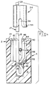
- an electric terminal comprising a pair of juxtaposed wire gripping plates connected in face to face spaced relationship by a bight of the terminal material, the plates having free edges which face away from the bight and one of the plates having an extension projecting away from the bight and beyond the other plate, is characterized in that the other plate is bowed towards the one plate in the vicinity of the bight, so as to be contiguous with the other plate at the crest of the bow, the other plate having serrations formed in its surface facing the one plate and extending from the free edge of the other plate towards the bight.
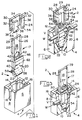
- the connector which is generally referenced 2, comprises an insulating housing 4 having side walls 6, end walls 8, and a base wall 10 defining a terminal receiving cavity 12.
- the housing has an open end 14, the opposed end walls 8 of the housing each being formed with a wire receiving slot 16 extending from the open end 14 towards the base wall 10.
- a one piece electrical terminal 17 comprising a pair of juxtaposed wire gripping plates 18 and 20 connected in face to face spaced relationship by a bight 22 of the terminal material, is insertable into the cavity 12 through the open end 14 of the housing 4, with the bight 22 leading.
- a clip 24 is slidable along the plates 18 and 20, towards the bight 22, from the position in which the clip 24 is shown in Figures 2 and 4 and that in which it is shown in Figures 3, 5 and 6, to drive the plates 18 and 20 relatively towards each other to compress between them a fine magnet wire W, following the insertion of the terminal 17 into the cavity 12 and the subsequent insertion of the wire W into the wire receiving slots 16 and between the plates 18 and 20 as shown in Figure 2.
- the plate 18 has an extension 26 which projects beyond the plate 20 to provide a guide for the clip 24, which is first pushed over the extension 26 as shown in Figure 2 prior to the insertion of the terminal 17 into the cavity 12.
- a circular opening 27 in the extension 26 serves for receiving an electrical lead wire (not shown) to be soldered to the extension 26.
- a free end edge 29 of the extension 26 faces away from the bight 22.
- the extension 26 has embossed longitudinal edge portions 28 each of which is slidably engaged between a rear wall 34 of the clip 24 and a respective bead 30 which projects inwardly of the clip 24 from an end wall 32 thereof.
- the clip 24 has two rudimentary front walls 36 which are connected to the rear wall 34 by the side walls 32.
- the side walls 32 are formed with recesses in the form of blind slots 48, which are precisely aligned with one another for receiving the wire W as the clip 24 is moved from its Figures 2 and 4 to its Figures 3, 5 and 6 positions, thereby to allow the clip 24 to be pushed fully home so as tightly to compress the wire W between the plates 18 and 20.
- the plate 20 is bowed towards the plate 18 in the vicinity of the bight 22 so as to be contiguous with the plate 18 at the crest 40 of the bow.
- the plate 20 has serrations 42, of keystone shape, formed in its surface 44 which faces the plate 18, the serrations 42 extending from a free end edge 46 of the plate 20 towards the bight 22.
- the cavity 12 has a reduced cross section first portion 48 (best seen in Figure 4) which is remote from the open end 14 and receives the bight 22, and an enlarged portion 50 for receiving the clip 24, a shoulder 52 defined by the housing 4, between the cavity portions 48 and 50 serving to limit the movement of the clip 24 towards the bight 22.
- the clip 24 has a resilient projection 54 at the lower end of each front wall 36 for engagement with the internal wall 56 of the cavity portion 50, as shown in Figure 5, thereby to restrain withdrawal of the clip 24 therefrom.
- the terminal 17 is provided with projecting barbs 58 on the longitudinal edges of the plates 18 and 20, in the vicinity of the bight 22 for engaging the wall 60 of the portion 48 of the cavity 12, to restrain withdrawal of the terminal 16 therefrom.
Landscapes
- Connections By Means Of Piercing Elements, Nuts, Or Screws (AREA)
- Multi-Conductor Connections (AREA)
- Connector Housings Or Holding Contact Members (AREA)
Abstract
Claims (9)
Applications Claiming Priority (2)
| Application Number | Priority Date | Filing Date | Title |
|---|---|---|---|
| GB8613299 | 1986-06-02 | ||
| GB868613299A GB8613299D0 (en) | 1986-06-02 | 1986-06-02 | Electrical connector |
Publications (2)
| Publication Number | Publication Date |
|---|---|
| EP0270602A1 EP0270602A1 (fr) | 1988-06-15 |
| EP0270602B1 true EP0270602B1 (fr) | 1991-05-22 |
Family
ID=10598765
Family Applications (1)
| Application Number | Title | Priority Date | Filing Date |
|---|---|---|---|
| EP19870903581 Expired EP0270602B1 (fr) | 1986-06-02 | 1987-05-08 | Connecteur electrique et borne electrique |
Country Status (5)
| Country | Link |
|---|---|
| EP (1) | EP0270602B1 (fr) |
| JP (1) | JPH07123054B2 (fr) |
| ES (1) | ES1002591Y (fr) |
| GB (1) | GB8613299D0 (fr) |
| WO (1) | WO1987007773A1 (fr) |
Cited By (2)
| Publication number | Priority date | Publication date | Assignee | Title |
|---|---|---|---|---|
| US10181658B2 (en) | 2016-03-31 | 2019-01-15 | Borgwarner Inc. | Electric machine with electrical connector |
| CN109216949A (zh) * | 2017-07-06 | 2019-01-15 | 泰科电子(Amp)意大利公司 | 电连接器 |
Families Citing this family (1)
| Publication number | Priority date | Publication date | Assignee | Title |
|---|---|---|---|---|
| JP5948180B2 (ja) * | 2012-07-31 | 2016-07-06 | タイコエレクトロニクスジャパン合同会社 | 電気端子 |
Family Cites Families (5)
| Publication number | Priority date | Publication date | Assignee | Title |
|---|---|---|---|---|
| FR1169034A (fr) * | 1956-12-21 | 1958-12-19 | Mors Electricite | Dispositif de connexion rapide de conducteurs électriques |
| GB958818A (en) * | 1962-05-11 | 1964-05-27 | Standard Telephones Cables Ltd | Improvements in or relating to electrical connectors |
| GB1178405A (en) * | 1967-08-11 | 1970-01-21 | Int Standard Electric Corp | Improvements in or relating to Electrical Jointing. |
| DE1963789A1 (de) * | 1969-12-19 | 1971-06-24 | Siemens Ag | Anordnung zur loetfreien Verbindung eines isolierten elektrischen Leiters mit einem Anschlussstift |
| GB1522863A (en) * | 1975-02-05 | 1978-08-31 | Amp Inc | Electrical connectors |
-
1986
- 1986-06-02 GB GB868613299A patent/GB8613299D0/en active Pending
-
1987
- 1987-05-08 EP EP19870903581 patent/EP0270602B1/fr not_active Expired
- 1987-05-08 JP JP62503196A patent/JPH07123054B2/ja not_active Expired - Lifetime
- 1987-05-08 WO PCT/US1987/001055 patent/WO1987007773A1/fr not_active Ceased
- 1987-06-01 ES ES8701834U patent/ES1002591Y/es not_active Expired
Cited By (3)
| Publication number | Priority date | Publication date | Assignee | Title |
|---|---|---|---|---|
| US10181658B2 (en) | 2016-03-31 | 2019-01-15 | Borgwarner Inc. | Electric machine with electrical connector |
| CN109216949A (zh) * | 2017-07-06 | 2019-01-15 | 泰科电子(Amp)意大利公司 | 电连接器 |
| CN109216949B (zh) * | 2017-07-06 | 2021-06-29 | 泰连意大利经销公司 | 电连接器 |
Also Published As
| Publication number | Publication date |
|---|---|
| WO1987007773A1 (fr) | 1987-12-17 |
| JPS63503493A (ja) | 1988-12-15 |
| JPH07123054B2 (ja) | 1995-12-25 |
| EP0270602A1 (fr) | 1988-06-15 |
| ES1002591U (es) | 1988-06-16 |
| GB8613299D0 (en) | 1986-07-09 |
| ES1002591Y (es) | 1989-02-01 |
Similar Documents
| Publication | Publication Date | Title |
|---|---|---|
| EP0002099B1 (fr) | Borne électrique à plaque fendue | |
| EP0021731B1 (fr) | Elément de contact électrique et connecteur incorporant de tels éléments de contact | |
| US6206722B1 (en) | Micro connector assembly and method of making the same | |
| US4036545A (en) | Connector assembly | |
| JPS603745B2 (ja) | 電気接続子 | |
| IE51215B1 (en) | Self-clamping electrical connectors and terminal blocks | |
| EP0000624A1 (fr) | Connecteur électrique à lame fendue | |
| JPS6028108B2 (ja) | 電気コネクタ | |
| US4749366A (en) | Heavy current electrical termination means | |
| US5306177A (en) | Insulation displacement termination system for input-output electrical connector | |
| GB1486075A (en) | Electrical connector and a method of making an electrical connection | |
| EP0136123B1 (fr) | Connecteur électrique destiné à s'accoupler avec trois languettes ayant une disposition orthogonale | |
| EP0007194B1 (fr) | Connecteur électrique perçant l'isolation d'un fil | |
| US3414865A (en) | Electrical connectors | |
| US4973267A (en) | ID composite connector for switch, and method | |
| US6991488B2 (en) | Electrical connector devices and methods for employing same | |
| EP0270602B1 (fr) | Connecteur electrique et borne electrique | |
| EP0021730B1 (fr) | Contact électrique pouvant recevoir un contact associé selon l'une ou l'autre de deux orientations mutuellement perpendiculaires | |
| US4530560A (en) | Plug and socket connector for terminating small gauge magnet wire | |
| EP0171193A2 (fr) | Terminal double en tôle métallique pénétrant dans l'isolation | |
| EP0600402B1 (fr) | Connecteur électrique avec retenue de contact améliorée | |
| JPS6276176A (ja) | 電気コネクタ組立体 | |
| US4540224A (en) | Grounding clip for use with shielded, jacketed flat cable | |
| EP0238538B1 (fr) | Connecteur et borne electriques | |
| EP0005350B1 (fr) | Couvercle pour borne électrique |
Legal Events
| Date | Code | Title | Description |
|---|---|---|---|
| PUAI | Public reference made under article 153(3) epc to a published international application that has entered the european phase |
Free format text: ORIGINAL CODE: 0009012 |
|
| AK | Designated contracting states |
Kind code of ref document: A1 Designated state(s): AT BE CH DE FR GB IT LI LU NL |
|
| 17P | Request for examination filed |
Effective date: 19880202 |
|
| R17P | Request for examination filed (corrected) |
Effective date: 19880202 |
|
| RAP1 | Party data changed (applicant data changed or rights of an application transferred) |
Owner name: AMP INCORPORATED |
|
| RBV | Designated contracting states (corrected) |
Designated state(s): DE FR GB IT NL |
|
| RAP1 | Party data changed (applicant data changed or rights of an application transferred) |
Owner name: AMP INCORPORATED |
|
| 17Q | First examination report despatched |
Effective date: 19900814 |
|
| GRAA | (expected) grant |
Free format text: ORIGINAL CODE: 0009210 |
|
| AK | Designated contracting states |
Kind code of ref document: B1 Designated state(s): DE FR GB IT NL |
|
| ITF | It: translation for a ep patent filed | ||
| REF | Corresponds to: |
Ref document number: 3770247 Country of ref document: DE Date of ref document: 19910627 |
|
| ET | Fr: translation filed | ||
| PLBE | No opposition filed within time limit |
Free format text: ORIGINAL CODE: 0009261 |
|
| STAA | Information on the status of an ep patent application or granted ep patent |
Free format text: STATUS: NO OPPOSITION FILED WITHIN TIME LIMIT |
|
| 26N | No opposition filed | ||
| REG | Reference to a national code |
Ref country code: GB Ref legal event code: 732E |
|
| PGFP | Annual fee paid to national office [announced via postgrant information from national office to epo] |
Ref country code: GB Payment date: 19950407 Year of fee payment: 9 |
|
| PGFP | Annual fee paid to national office [announced via postgrant information from national office to epo] |
Ref country code: FR Payment date: 19950517 Year of fee payment: 9 |
|
| PGFP | Annual fee paid to national office [announced via postgrant information from national office to epo] |
Ref country code: NL Payment date: 19950531 Year of fee payment: 9 Ref country code: DE Payment date: 19950531 Year of fee payment: 9 |
|
| PG25 | Lapsed in a contracting state [announced via postgrant information from national office to epo] |
Ref country code: GB Effective date: 19960508 |
|
| PG25 | Lapsed in a contracting state [announced via postgrant information from national office to epo] |
Ref country code: NL Effective date: 19961201 |
|
| GBPC | Gb: european patent ceased through non-payment of renewal fee |
Effective date: 19960508 |
|
| PG25 | Lapsed in a contracting state [announced via postgrant information from national office to epo] |
Ref country code: FR Effective date: 19970131 |
|
| PG25 | Lapsed in a contracting state [announced via postgrant information from national office to epo] |
Ref country code: DE Effective date: 19970201 |
|
| NLV4 | Nl: lapsed or anulled due to non-payment of the annual fee |
Effective date: 19961201 |
|
| REG | Reference to a national code |
Ref country code: FR Ref legal event code: ST |
|
| PG25 | Lapsed in a contracting state [announced via postgrant information from national office to epo] |
Ref country code: IT Free format text: LAPSE BECAUSE OF NON-PAYMENT OF DUE FEES;WARNING: LAPSES OF ITALIAN PATENTS WITH EFFECTIVE DATE BEFORE 2007 MAY HAVE OCCURRED AT ANY TIME BEFORE 2007. THE CORRECT EFFECTIVE DATE MAY BE DIFFERENT FROM THE ONE RECORDED. Effective date: 20050508 |