EP0271221A1 - Vorrichtung zur Produktbehandlung - Google Patents
Vorrichtung zur Produktbehandlung Download PDFInfo
- Publication number
- EP0271221A1 EP0271221A1 EP19870309954 EP87309954A EP0271221A1 EP 0271221 A1 EP0271221 A1 EP 0271221A1 EP 19870309954 EP19870309954 EP 19870309954 EP 87309954 A EP87309954 A EP 87309954A EP 0271221 A1 EP0271221 A1 EP 0271221A1
- Authority
- EP
- European Patent Office
- Prior art keywords
- food
- air jets
- food sticks
- sticks
- biassing
- Prior art date
- Legal status (The legal status is an assumption and is not a legal conclusion. Google has not performed a legal analysis and makes no representation as to the accuracy of the status listed.)
- Withdrawn
Links
- 235000013305 food Nutrition 0.000 claims abstract description 83
- 238000013459 approach Methods 0.000 claims description 6
- 235000015168 fish fingers Nutrition 0.000 abstract description 3
- 230000004048 modification Effects 0.000 description 2
- 238000012986 modification Methods 0.000 description 2
Images



Classifications
-
- B—PERFORMING OPERATIONS; TRANSPORTING
- B65—CONVEYING; PACKING; STORING; HANDLING THIN OR FILAMENTARY MATERIAL
- B65G—TRANSPORT OR STORAGE DEVICES, e.g. CONVEYORS FOR LOADING OR TIPPING, SHOP CONVEYOR SYSTEMS OR PNEUMATIC TUBE CONVEYORS
- B65G47/00—Article or material-handling devices associated with conveyors; Methods employing such devices
- B65G47/22—Devices influencing the relative position or the attitude of articles during transit by conveyors
- B65G47/24—Devices influencing the relative position or the attitude of articles during transit by conveyors orientating the articles
- B65G47/248—Devices influencing the relative position or the attitude of articles during transit by conveyors orientating the articles by turning over or inverting them
-
- B—PERFORMING OPERATIONS; TRANSPORTING
- B65—CONVEYING; PACKING; STORING; HANDLING THIN OR FILAMENTARY MATERIAL
- B65G—TRANSPORT OR STORAGE DEVICES, e.g. CONVEYORS FOR LOADING OR TIPPING, SHOP CONVEYOR SYSTEMS OR PNEUMATIC TUBE CONVEYORS
- B65G2203/00—Indexing code relating to control or detection of the articles or the load carriers during conveying
- B65G2203/04—Detection means
- B65G2203/042—Sensors
Definitions
- This invention relates to a product handling mechanism, more particularly a mechanism for turning fish fingers or like slab-like stick food products, hereinafter refered to as "food sticks" from an on-edge disposition to a flat disposition.
- Such mechanism is known in which a plurality of upright divider blocks are spaced apart by lifters, which are adapted to receive food sticks on-edge from a feed conveyor, the lifters being provided with laterally offset longitudinally extending peaks for contact with the food sticks offset from the centre-planes of the food sticks, whereby upon lifting of the food sticks by the lifters the food sticks tend to turn in one and the same direction towards the flat disposition, and the face of each divider block towards which the respective food stick tends to turn has an upper portion inclined away upwardly to assist in turning the food stick into the flat disposition as the peak of the respective lifter approaches the same level as the top of the divider block.
- there will be one more divider block than lifters which divider block will not need to have any face portion inclined away upwardly because the adjacent lifter will tend to turn a food stick towards the next divider block.
- the speed of operation of the lifters must be slow enough to ensure that the food sticks on all the lifters are fully turned into the flat disposition on top of the divider blocks before operation of a pusher which is reciprocable along the length of the divider blocks to move the food sticks further in the feed direction in flat disposition.
- sensors are provided one adjacent the trailing end of each lifter, to detect the presence of a food stick on the lifter, the pusher only being operated when all the sensors have detected the presence of food sticks.
- the object of the present invention is to provide improved mechanism for turning food sticks from on-edge disposition to flat disposition.
- the face of each divider block opposite the portion of the face of the adjacent block that is inclined away upwardly is provided with at least one biassing air jet, and all the biassing air jets are connected to pressure air control means, whereby, as lifting of the food sticks commences, blasts of air from the biassing air jets initiate rapid turning of the food sticks by impinging on the adjacent faces of the food sticks adjacent their edges remote from the lifters.
- At least two biassing air jets are provided within the length of each divider block, so that a pair of air blasts will impinge on each food stick at spaced positions along its length.
- At least one counter air jet (and preferably two) is provided in the face of each divider block below the portion that is inclined away upwardly, and all the counter air jets are connected to pressure air control means, whereby, as food sticks arrive on the lifters, blasts of air from the counter air jets urge each food stick over to contact the next divider block, for correct positioning on the peak of the respective lifter.
- One pressure air control means may serve for both the biassing air jets and the counter air jets, which may be operated in sequence, or they may be supplied with pressure air continuously, in view of the high speed of operation of the turning mechanism achieved by the invention and the cyclical closing of the air jets by the raised lifters.
- Each lifter preferably is adapted to be lifted until their peaks extend above the tops of the divider blocks, whereby the peaks can form guides for food sticks in flat disposition supported on the tops of the divider blocks, and preferably adjacent body portions of the lifters, the pusher being provided with notches in its underside to pass along the peaks as the pusher is operated to move the food sticks further in the feed direction in flat disposition.
- the divider blocks may be provided with facing plates, with holes for the biassing air jets, and may have upward extensions first inclined away from the divider blocks to afford assistance in the turning of the food sticks as they approach the flat disposition, then extending vertically to form guides for food sticks in flat disposition.
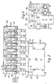
- the product handling mechanism illustrated in part in Figures 1 to 4 is for turning fish fingers or like slab-like food products, or food sticks 10, from an on-edge disposition ( Figure 2) to a flat disposition ( Figure 3), and is basically a known mechanism in which a plurality of upright divider blocks 11 are spaced apart by lifters 12, which receive the food sticks 10 on-edge from a feed conveyor 13, the lifters being provided with laterally offset longitudinally extending peaks 14 for contact with the food sticks offset from the centre-planes of the food sticks, whereby upon lifting of the food sticks by the lifters (from the position shown in Figure 2) the food sticks tend to turn in one and the same direction towards the flat disposition (which is finally achieved in Figure 3), and the face 15 of each divider block 11 towards which the respective food stick 10 tends to turn has an upper portion 16 inclined away upwardly to assist in turning the food stick into the flat disposition as the peak 14 of the respective lifter approaches the same level as the top 17 of the divider block.
- the speed of operation of the lifters in the known mechanism must be slow enough to ensure that the food sticks on all the lifters are fully turned into the flat disposition on top of the divider blocks before operation of a pusher 18 which is reciprocable along the length of the divider blocks to move the food sticks further in the feed direction in flat disposition.
- sensors 19 are provided one adjacent the trailing end 20 of each lifter 12, to detect the presence of a food stick 10 on the lifter, the pusher 18 only being operated when all the sensors have detected the presence of food sticks.
- the lifters 12 are bolted to a plate 21 having clamps 22 securing it to guide rods 23 reciprocable (by means not shown) in blocks 24 on a plate 25 adapted to be secured to a part 26 ( Figure 1) of a frame.
- the pusher 18 is suspended from blocks 27 (only one shown in Figure 1) reciprocable (by means not shown) on guide bars 28 extending between frame members 29.
- Each sensor 19 comprises a finger 30 projecting upwards from a pivot 31 and also extending downwards to a screw-threaded rod 32 carrying an axially adjustable counterbalance weight 33 for an axially adjustable saddle 34, which actuates a proximity switch 35 when the finger 30 is pushed by a food stick 10 pushed on to the respective lifter 12 all the sensors being carried by a frame part 36, and all the proximity switches being connected in series with actuating means (not shown) for the pusher.
- each divider block 11 opposite the inclined portion 16 of the face 15 of the adjacent divider block is provided with two biassing air jets 38 and all the biassing air jets connected via holes 39, 40 in the blocks and a manifold 41 (see also Figures 2 and 3) to pressure air control means 42, whereby, as lifting of the food sticks 10 commences, blasts of air from the biassing air jets 38 initiate rapid turning of the foods sticks by impinging on the adjacent faces 43 (see Figure 5) of the food sticks adjacent their edges 44 remote from the lifters.
- Two counter air jets 45 are provided in the face 15 of each divider block 11 below the portion 16 inclined away upwardly, and all the counter air jets are connected via holes 46, 47 in the blocks and a manifold 48 to the pressure air control means, whereby, blasts of air from the counter air jets 45 urge each food stick 10 over to contact the next divider block, for correct positioning on the peak 14 of the respective lifter.
- pressure air control means 42 may be such that the biassing air jets 38 and the counter air jets 45 are operated in sequence, it is convenient for pressure air to be supplied continuously to all the jets in view of the high speed of operation of the turning mechanism achieved by the invention and the cyclical closing of the air jets 38, 45 by the raised lifters 12 as will be apparent from the sequence shown in Figure 5.
- the peaks 14 can form guides for food sticks 10 in the flat disposition, the pusher 18 being provided with notches 50 in its underside to pass along the peaks 14 as the pusher is operated to move the foods sticks further in the feed direction in flat disposition, e.g., on to a shelf 51 ( Figure 1) or a conveyor at that level.
- the last divider block 11Y ( Figures 2 and 3), not being followed by another lifter 12, is provided with a facing plate 52 with an upward extension 53 (see also Figure 1) bent out to form a guide in place of the peak 14 of a lifter.
- all the divider blocks 11 and the first divider block 11X are provided with facing plates 52, with holes for the biassing air jets 38, and - as shown in Figure 6 - these plates may have upward extensions 54 first inclined upwardly away from the divider blocks to afford assistance in the turning of the food sticks 10 as they approach the flat disposition, then extending vertically to form guides for the food sticks in flat disposition.
Landscapes
- Engineering & Computer Science (AREA)
- Mechanical Engineering (AREA)
- Specific Conveyance Elements (AREA)
- Meat, Egg Or Seafood Products (AREA)
Applications Claiming Priority (2)
| Application Number | Priority Date | Filing Date | Title |
|---|---|---|---|
| GB8626986 | 1986-11-12 | ||
| GB868626986A GB8626986D0 (en) | 1986-11-12 | 1986-11-12 | Product handling mechanism |
Publications (1)
| Publication Number | Publication Date |
|---|---|
| EP0271221A1 true EP0271221A1 (de) | 1988-06-15 |
Family
ID=10607189
Family Applications (1)
| Application Number | Title | Priority Date | Filing Date |
|---|---|---|---|
| EP19870309954 Withdrawn EP0271221A1 (de) | 1986-11-12 | 1987-11-11 | Vorrichtung zur Produktbehandlung |
Country Status (2)
| Country | Link |
|---|---|
| EP (1) | EP0271221A1 (de) |
| GB (2) | GB8626986D0 (de) |
Cited By (1)
| Publication number | Priority date | Publication date | Assignee | Title |
|---|---|---|---|---|
| CN113277296A (zh) * | 2021-05-27 | 2021-08-20 | 广东韶钢松山股份有限公司 | 一种弯曲钢坯自动翻转装置及方法 |
Citations (8)
| Publication number | Priority date | Publication date | Assignee | Title |
|---|---|---|---|---|
| FR1549604A (de) * | 1967-11-20 | 1968-12-13 | ||
| DE1601080A1 (de) * | 1963-04-06 | 1969-08-21 | Gram Brdr As | Verfahren und Vorrichtung zur Entfernung gefrorener Formkoerper und Gefriertaschen eines Gefriertisches |
| US4030898A (en) * | 1974-11-27 | 1977-06-21 | Masahiro Morita | Quick freezing apparatus |
| DE3028310A1 (de) * | 1979-07-26 | 1981-02-12 | Gen Mills Inc | Verfahren und vorrichtung zum zerschneiden von bloecken aus gefrorenem fisch o.dgl. in einzelne staebchen |
| GB2054360A (en) * | 1979-05-31 | 1981-02-18 | Gen Mills Inc | Apparatus and method for severing frozen columns of foodstuff |
| DE3402611A1 (de) * | 1984-01-26 | 1985-08-01 | Siegfried 2222 Marne Schwarz | Verfahren und vorrichtung zur herstellung und langzeitkonservierung von schnitzeln aus fisch, insbesondere aus seelachs, kabeljau o.dgl. gadidenarten |
| FR2560500A1 (fr) * | 1984-03-05 | 1985-09-06 | Stela Inox | Unite de decongelation |
| WO1986001081A1 (fr) * | 1984-08-03 | 1986-02-27 | Mitsui & Co., Ltd | Procede et installation de congelation d'aliments |
-
1986
- 1986-11-12 GB GB868626986A patent/GB8626986D0/en active Pending
-
1987
- 1987-11-11 GB GB8726381A patent/GB2197284B/en not_active Expired - Fee Related
- 1987-11-11 EP EP19870309954 patent/EP0271221A1/de not_active Withdrawn
Patent Citations (9)
| Publication number | Priority date | Publication date | Assignee | Title |
|---|---|---|---|---|
| DE1601080A1 (de) * | 1963-04-06 | 1969-08-21 | Gram Brdr As | Verfahren und Vorrichtung zur Entfernung gefrorener Formkoerper und Gefriertaschen eines Gefriertisches |
| FR1549604A (de) * | 1967-11-20 | 1968-12-13 | ||
| US4030898A (en) * | 1974-11-27 | 1977-06-21 | Masahiro Morita | Quick freezing apparatus |
| GB2054360A (en) * | 1979-05-31 | 1981-02-18 | Gen Mills Inc | Apparatus and method for severing frozen columns of foodstuff |
| DE3028310A1 (de) * | 1979-07-26 | 1981-02-12 | Gen Mills Inc | Verfahren und vorrichtung zum zerschneiden von bloecken aus gefrorenem fisch o.dgl. in einzelne staebchen |
| GB2054363A (en) * | 1979-07-26 | 1981-02-18 | Gen Mills Inc | Severing frozen food |
| DE3402611A1 (de) * | 1984-01-26 | 1985-08-01 | Siegfried 2222 Marne Schwarz | Verfahren und vorrichtung zur herstellung und langzeitkonservierung von schnitzeln aus fisch, insbesondere aus seelachs, kabeljau o.dgl. gadidenarten |
| FR2560500A1 (fr) * | 1984-03-05 | 1985-09-06 | Stela Inox | Unite de decongelation |
| WO1986001081A1 (fr) * | 1984-08-03 | 1986-02-27 | Mitsui & Co., Ltd | Procede et installation de congelation d'aliments |
Cited By (2)
| Publication number | Priority date | Publication date | Assignee | Title |
|---|---|---|---|---|
| CN113277296A (zh) * | 2021-05-27 | 2021-08-20 | 广东韶钢松山股份有限公司 | 一种弯曲钢坯自动翻转装置及方法 |
| CN113277296B (zh) * | 2021-05-27 | 2023-06-27 | 广东韶钢松山股份有限公司 | 一种弯曲钢坯自动翻转装置及方法 |
Also Published As
| Publication number | Publication date |
|---|---|
| GB2197284B (en) | 1990-01-17 |
| GB8626986D0 (en) | 1986-12-10 |
| GB8726381D0 (en) | 1987-12-16 |
| GB2197284A (en) | 1988-05-18 |
Similar Documents
| Publication | Publication Date | Title |
|---|---|---|
| US4599025A (en) | Stacker assembly | |
| CA1195706A (en) | Blank stacking apparatus | |
| US3521763A (en) | Automatic pan unstacker | |
| US4583965A (en) | Assembly for unfolding flattened cartons in packaging machinery | |
| US3698707A (en) | Sheet stacker and control stack removing means | |
| EP0128669B1 (de) | Einrichtungen zum Trennen aneinanderhängender Gegenstände | |
| WO1986006356A1 (en) | A device in a machine handling package units | |
| RU2066671C1 (ru) | Предохранительное устройство к стапелеприемнику и стапелеприемник в самонакладе и в выводном устройстве листовой печатной машины | |
| US4336874A (en) | Setting machine for spacing formed articles | |
| US4120392A (en) | Coil spring feeding apparatus | |
| US6485016B1 (en) | Stack changing device | |
| EP1105327A2 (de) | Anordnung zur vereinzelung von nebeneinanderliegenden paketen | |
| US4249841A (en) | Wire picking from a wire bundle | |
| US4069925A (en) | Apparatus for stacking hanging plates | |
| US3740029A (en) | Apparatus for removing sheets from stacks | |
| FI86624C (fi) | Anordning foer stapling av vikta tryckprodukter. | |
| US5460480A (en) | Installation for handling the conveyance of blanks from a cutting machine to a stacking device | |
| JPS6186039A (ja) | 長い線材や棒材の個別化装置 | |
| GB2197284A (en) | Product handling and turning mechanism | |
| US4342531A (en) | Method and apparatus for handling bricks | |
| JPH0566303B2 (de) | ||
| US3842965A (en) | Sheet pile feeding device | |
| AU607574B2 (en) | Apparatus for correcting the lateral position of a sheet element in a feed station of a machine processing said sheet | |
| DE10142389B4 (de) | Pneumatische Trennvorrichtung | |
| US3101156A (en) | Method and apparatus for feeding flat sheets onto a moving conveyor |
Legal Events
| Date | Code | Title | Description |
|---|---|---|---|
| PUAI | Public reference made under article 153(3) epc to a published international application that has entered the european phase |
Free format text: ORIGINAL CODE: 0009012 |
|
| AK | Designated contracting states |
Kind code of ref document: A1 Designated state(s): DE GB SE |
|
| 17P | Request for examination filed |
Effective date: 19881129 |
|
| RBV | Designated contracting states (corrected) |
Designated state(s): DE SE |
|
| 17Q | First examination report despatched |
Effective date: 19900627 |
|
| STAA | Information on the status of an ep patent application or granted ep patent |
Free format text: STATUS: THE APPLICATION IS DEEMED TO BE WITHDRAWN |
|
| 18D | Application deemed to be withdrawn |
Effective date: 19901108 |
|
| RIN1 | Information on inventor provided before grant (corrected) |
Inventor name: PIKE, BRIAN CHARLES |