EP0271258A2 - Dispositif pour projeter du matériau granulaire ou particulaire - Google Patents
Dispositif pour projeter du matériau granulaire ou particulaire Download PDFInfo
- Publication number
- EP0271258A2 EP0271258A2 EP87310432A EP87310432A EP0271258A2 EP 0271258 A2 EP0271258 A2 EP 0271258A2 EP 87310432 A EP87310432 A EP 87310432A EP 87310432 A EP87310432 A EP 87310432A EP 0271258 A2 EP0271258 A2 EP 0271258A2
- Authority
- EP
- European Patent Office
- Prior art keywords
- air
- nozzle
- air gap
- flow
- bleed
- Prior art date
- Legal status (The legal status is an assumption and is not a legal conclusion. Google has not performed a legal analysis and makes no representation as to the accuracy of the status listed.)
- Withdrawn
Links
Images

Classifications
-
- F—MECHANICAL ENGINEERING; LIGHTING; HEATING; WEAPONS; BLASTING
- F04—POSITIVE - DISPLACEMENT MACHINES FOR LIQUIDS; PUMPS FOR LIQUIDS OR ELASTIC FLUIDS
- F04F—PUMPING OF FLUID BY DIRECT CONTACT OF ANOTHER FLUID OR BY USING INERTIA OF FLUID TO BE PUMPED; SIPHONS
- F04F5/00—Jet pumps, i.e. devices in which flow is induced by pressure drop caused by velocity of another fluid flow
- F04F5/44—Component parts, details, or accessories not provided for in, or of interest apart from, groups F04F5/02 - F04F5/42
- F04F5/46—Arrangements of nozzles
- F04F5/461—Adjustable nozzles
Definitions
- the present invention relates to a device for ejecting granular or particulate material.
- Devices for ejecting granular or particulate material from supply means for such material are known in the form of an elongate device through which the material flows, the device including a nozzle for the material, the nozzle defining an air gap in the device, to which gap air is supplied whereby as a result of the Venturi effect created in the device, the flow of material through the device is enhanced or enabled.
- a device for ejecting granular or particulate material from supply means comprising an elongate body for through flow of the material, a nozzle defining within the body an air gap, and means whereby air can be supplied to the air gap and as a result of the Venturi effect created thereby in the device flow of material through the device is enhanced or enabled, characterised in that the device is provided with a bleed arrangement for bleeding air to the material from the supply to the air gap before the material reaches the air gap. Bleeding air from the supply to the air gap to the material before it reaches the air gap can improve the flow of material through the device.
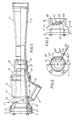
- reference numeral 1 designates an annular flange plate at an input end bolted to an annular flange connector 2 which is itself fastened by screws to a hollow body 3 having an air inlet 4 in a portion 5 of body 3 for connection to a source of compressed air.
- Body 3 is fastened by screws to a throat body 6 which is itself connected to a flared, diffuser body 7 via a locking nut 8 and a compression sleeve 9.
- Inside the body 3 is an elongate nozzle 10 defining at its innermost end an annular gap between itself and the inside face of body 6. This gap is adjustable in a manner which will be explained below, by adjusting longitudinally the position of the nozzle 10, reference numeral 11 designating an O-ring seal between nozzle 10 and body 3.
- the input end is coupled to the output of a device from which granular or particulate material is fed, for example a hopper supplied with such material.
- the material flows through the nozzle 10 and then through and out of the diffuser body 7 for subsequent handling of the material.
- the flow of the material is enabled or enhanced by supplying compressed air into inlet 4, this air emanating into the nozzle 10 through the annular gap between the innermost end of nozzle 10 and the inside face of body 6.
- the Venturi effect created where the air emanates from the annular gap the air laden with the granular or particulate material is sucked through nozzle 10 and into diffuser body 7.
- the nozzle 10 may be adjusted as regards its longitudinal position, to adjust the annular gap between its innermost end and the inner face of body 6 to achieve optimum flow of material.
- the body 3 is formed with a slot 12 through it, extending obliquely across the longitudinal axis of the ejecting device; and the nozzle 10 has two blind holes 13 and 14, these blind holes being spaced 60° apart circumferentially.
- a bar 15 is inserted into the blind hole 13 (see Figure 3) and rotated in an anti-clockwise direction in Figure 3.
- the bar 15 slides in slot 12 and, due to the latter being oblique, the nozzle 10 is pulled towards the left in Figure 1.
- the blind hole 14 appears under the above-mentioned one end of slot 12.
- the bar 15 may be inserted into the blind hole 14 and rotated again in an anti-clockwise direction in Figure 3, to pull the nozzle 10 further to the left in Figure 1.
- the bar 15 is again at the other end of slot 12, and the nozzle 10 has rotated a total of 120° and has been pulled in total from the position shown in Figure 1 to a position in which its left hand end in Figure 1 (i.e. its outermost end) is at the junction of flange plate 1 and connector 2, as shown by a broken line in Figure 1, and the annular gap is as large as permissible.
- the annular gap is set to a value which achieves optimum flow of material by adjustment of nozzle 10, the latter then being locked in place by a grub-screw 16 passing through body 3.
- Reference numeral 17 denotes a scale marked on the outside of body 3, for use in resetting the nozzle to a desired position with reference to its innermost position.
- reference numeral 18 designates the body arrangement 3/6/7 of the ejecting device
- reference numeral 19 designates a compressed air line feeding inlet 4
- reference numeral 20 denotes a hopper for feeding material to the body arrangement 3/6/7 of the device 18 via an input chamber 21.
- line 22 connected between line 19 and chamber 21 via an adjustable throttle in the form of a tap 23 for controlling the degree of air "bleed". It has been found that providing such a "bleed" of air to the material can improve the flow of material through the device 18.
Landscapes
- Engineering & Computer Science (AREA)
- Physics & Mathematics (AREA)
- Fluid Mechanics (AREA)
- Mechanical Engineering (AREA)
- General Engineering & Computer Science (AREA)
- Nozzles (AREA)
- Air Transport Of Granular Materials (AREA)
Applications Claiming Priority (2)
| Application Number | Priority Date | Filing Date | Title |
|---|---|---|---|
| GB8629647 | 1986-12-11 | ||
| GB08629647A GB2198479A (en) | 1986-12-11 | 1986-12-11 | Ejecting granular or particulate material |
Publications (2)
| Publication Number | Publication Date |
|---|---|
| EP0271258A2 true EP0271258A2 (fr) | 1988-06-15 |
| EP0271258A3 EP0271258A3 (fr) | 1988-10-05 |
Family
ID=10608857
Family Applications (1)
| Application Number | Title | Priority Date | Filing Date |
|---|---|---|---|
| EP87310432A Withdrawn EP0271258A3 (fr) | 1986-12-11 | 1987-11-26 | Dispositif pour projeter du matériau granulaire ou particulaire |
Country Status (2)
| Country | Link |
|---|---|
| EP (1) | EP0271258A3 (fr) |
| GB (1) | GB2198479A (fr) |
Cited By (1)
| Publication number | Priority date | Publication date | Assignee | Title |
|---|---|---|---|---|
| WO2013072410A1 (fr) | 2011-11-16 | 2013-05-23 | Basf Se | Injecteur pour un solide granulaire |
Families Citing this family (2)
| Publication number | Priority date | Publication date | Assignee | Title |
|---|---|---|---|---|
| RU2180410C2 (ru) * | 2000-04-14 | 2002-03-10 | Волгоградский государственный технический университет | Струйный насос |
| RU2353820C1 (ru) * | 2008-01-09 | 2009-04-27 | Открытое акционерное общество "Северо-Кавказский научно-исследовательский проектный институт природных газов" (ОАО "СевКавНИПИгаз") | Эжектор |
Family Cites Families (2)
| Publication number | Priority date | Publication date | Assignee | Title |
|---|---|---|---|---|
| DE444471C (de) * | 1926-02-26 | 1927-05-21 | Kohlenstaub Ges Mit Beschraenk | Verfahren zum Foerdern von Kohlenstaub |
| FR677735A (fr) * | 1929-07-02 | 1930-03-13 | Pneumatic Conveyance & Extract | Appareils de manutention pneumatique de matières solides |
-
1986
- 1986-12-11 GB GB08629647A patent/GB2198479A/en not_active Withdrawn
-
1987
- 1987-11-26 EP EP87310432A patent/EP0271258A3/fr not_active Withdrawn
Cited By (1)
| Publication number | Priority date | Publication date | Assignee | Title |
|---|---|---|---|---|
| WO2013072410A1 (fr) | 2011-11-16 | 2013-05-23 | Basf Se | Injecteur pour un solide granulaire |
Also Published As
| Publication number | Publication date |
|---|---|
| EP0271258A3 (fr) | 1988-10-05 |
| GB8629647D0 (en) | 1987-01-21 |
| GB2198479A (en) | 1988-06-15 |
Similar Documents
| Publication | Publication Date | Title |
|---|---|---|
| CA1284808C (fr) | Systeme de buse pour systeme transporteur haute vitesse a vis sans fin, et methode d'acheminement d'un vrac | |
| US3504945A (en) | Pneumatic conveyor system | |
| DE3865442D1 (de) | Verfahren und vorrichtung zum mikronisieren von feststoffen in strahlmuehlen. | |
| US3914093A (en) | Combustion apparatus | |
| SI1482245T1 (sl) | Naprava za regulacijo razmerja plin/zrak za predmeSalno zgorevalno napravo | |
| EP0272010A2 (fr) | Dispositif pour projeter du matériau granulaire ou particulaire | |
| US4547938A (en) | Yarn texturing jet | |
| US3973802A (en) | Conveyor line fluidizer | |
| GB2198479A (en) | Ejecting granular or particulate material | |
| WO1990010794A3 (fr) | Appareil de pompage de fluide | |
| US5005768A (en) | Spray nozzle | |
| SE514960C2 (sv) | Matningsanordning för cellulosamaterial | |
| US4574436A (en) | Yarn texturing jet | |
| US2500271A (en) | Pneumatic conveyer | |
| US2493387A (en) | Flow mixer | |
| US3685530A (en) | Flow-actuated bleed valve | |
| GB689680A (en) | Improvements in or relating to the pneumatic conveyance of materials | |
| JPS6140500A (ja) | 真空発生装置 | |
| GB2099778A (en) | Feeding station for pneumatic conveyors | |
| SU612872A1 (ru) | Устройство дл всасывани и пневмотранспорта сыпучих материалов | |
| CA2149798C (fr) | Venturi variable pour systemes de transporteurs pneumatiques | |
| CA1195229A (fr) | Regulateur d'admission de fluide a un bruleur fonctionnant par intermittence | |
| GB1192965A (en) | Improvements in Fluidics | |
| SU992938A1 (ru) | Воздухораспределительное устройство | |
| SU1524026A2 (ru) | Струйный регул тор расхода |
Legal Events
| Date | Code | Title | Description |
|---|---|---|---|
| PUAI | Public reference made under article 153(3) epc to a published international application that has entered the european phase |
Free format text: ORIGINAL CODE: 0009012 |
|
| AK | Designated contracting states |
Kind code of ref document: A2 Designated state(s): DE FR NL |
|
| PUAL | Search report despatched |
Free format text: ORIGINAL CODE: 0009013 |
|
| AK | Designated contracting states |
Kind code of ref document: A3 Designated state(s): DE FR NL |
|
| RHK1 | Main classification (correction) |
Ipc: B65G 53/14 |
|
| RAP1 | Party data changed (applicant data changed or rights of an application transferred) |
Owner name: WESTINGHOUSE BRAKE AND SIGNAL HOLDINGS LIMITED |
|
| STAA | Information on the status of an ep patent application or granted ep patent |
Free format text: STATUS: THE APPLICATION IS DEEMED TO BE WITHDRAWN |
|
| 18D | Application deemed to be withdrawn |
Effective date: 19890406 |
|
| RIN1 | Information on inventor provided before grant (corrected) |
Inventor name: BYE, LEONARD JAMES Inventor name: SMALL, STEVEN ALAN |