EP0271303B1 - Machine pour le montage des côtés de dessus de chaussures - Google Patents
Machine pour le montage des côtés de dessus de chaussures Download PDFInfo
- Publication number
- EP0271303B1 EP0271303B1 EP87310729A EP87310729A EP0271303B1 EP 0271303 B1 EP0271303 B1 EP 0271303B1 EP 87310729 A EP87310729 A EP 87310729A EP 87310729 A EP87310729 A EP 87310729A EP 0271303 B1 EP0271303 B1 EP 0271303B1
- Authority
- EP
- European Patent Office
- Prior art keywords
- shoe
- roll
- lasting
- shoe bottom
- aforesaid
- Prior art date
- Legal status (The legal status is an assumption and is not a legal conclusion. Google has not performed a legal analysis and makes no representation as to the accuracy of the status listed.)
- Expired - Lifetime
Links
- 230000002045 lasting effect Effects 0.000 title claims description 106
- 238000006073 displacement reaction Methods 0.000 claims description 31
- 230000000694 effects Effects 0.000 claims description 12
- 230000000712 assembly Effects 0.000 claims description 7
- 238000000429 assembly Methods 0.000 claims description 7
- 230000004044 response Effects 0.000 claims description 7
- 239000000463 material Substances 0.000 description 13
- 230000009471 action Effects 0.000 description 7
- 210000000481 breast Anatomy 0.000 description 5
- 239000000853 adhesive Substances 0.000 description 4
- 230000001070 adhesive effect Effects 0.000 description 4
- 230000008901 benefit Effects 0.000 description 4
- 230000015572 biosynthetic process Effects 0.000 description 3
- 238000005266 casting Methods 0.000 description 3
- 238000010276 construction Methods 0.000 description 2
- 238000003780 insertion Methods 0.000 description 2
- 230000037431 insertion Effects 0.000 description 2
- 230000004048 modification Effects 0.000 description 2
- 238000012986 modification Methods 0.000 description 2
- 230000009286 beneficial effect Effects 0.000 description 1
- 239000004568 cement Substances 0.000 description 1
- 230000003111 delayed effect Effects 0.000 description 1
- 230000003292 diminished effect Effects 0.000 description 1
- 230000000977 initiatory effect Effects 0.000 description 1
- 238000009877 rendering Methods 0.000 description 1
- 230000007480 spreading Effects 0.000 description 1
Images




Classifications
-
- A—HUMAN NECESSITIES
- A43—FOOTWEAR
- A43D—MACHINES, TOOLS, EQUIPMENT OR METHODS FOR MANUFACTURING OR REPAIRING FOOTWEAR
- A43D21/00—Lasting machines
- A43D21/006—Lasting machines with rotating lasting means
Definitions
- This invention is concerned with a machine for lasting side portions of shoe uppers comprising a shoe support for supporting, bottom uppermost, a shoe comprising a shoe upper on a last with an insole on the last bottom, side lasting instrumentalities comprising two wiper assemblies, arranged one at each side of the shoe support and each comprising a rotary lasting roll extending transversely of the shoe bottom and having a helical wiping element which engages the shoe upper for effecting an in-wiping force thereon as the roll rotates, together with means for effecting rotation of the rolls, and means for effecting relative movement, lengthwise of the shoe bottom, between the shoe support and the side lasting instrumentalities to cause the lasting rolls to operate progressively along opposite side portions of the shoe bottom.
- the final stage of lasting the shoe is constituted by a heel seat lasting operation in which, using wiper plates, the shoe upper material constituting the lasting margin is wiped over the insole edge and secured and any excess material is distributed in the form of pleats over the marginal surface of the insole; in this way, no significant loops or folds are formed in the upper material. It will of course be appreciated that excess material frequently arises because of the shape of the upper and the need for it to conform to the shape of the last such that the lasting margin of the upper can be secured satisfactorily to the insole.
- the in-wiping force applied by the said one lasting roll is enhanced in said predetermined region by bodily displacing it axially inwardly, such inward displacement serving to tighten the upper over the insole edge in said region and spread over a wider area the material which could otherwise form the fold, prior to its being secured to the insole.
- said one roll which is displaced axially inwardly as aforesaid is constituted by the roll operating on the "outside" margin of the shoe bottom, the arrangement being such that it is so axially displaced when it reaches the ball region of the shoe bottom. If desired, furthermore, both rolls may be displaced axially as aforesaid when they reach the ball region of the shoe bottom.
- said one roll which is displaced axially inwardly as aforesaid is constituted by the roll operating on the "outside" margin of the shoe bottom, the arrangement being such that it is so axially displaced when it reaches the waist region of the shoe bottom.
- the lasting rolls are mounted for pivotal movement about a heightwise axis thus to effect movement thereof, lengthwise of the shoe bottom, relative to the shoe support whereby the rolls are caused to operate progressively along opposite marginal portions of the shoe bottom as aforesaid, and wherein the axis of each roll as it pivots, passes through a position coincident with a perpendicular to the longitudinal centre line of the operating locality of the machine, the axial displacement of the roll takes place when it reaches the aforementioned position.
- the speed of relative movement between the shoe support and the side lasting instrumentalities may be reduced, or if desired the relative movement may be arrested.
- the lasting roll "dwells" at the point where the fold could otherwise arise and, by continued rotation of the helical wiping element, enhance still further the already enhanced in-wiping drafting force and the spreading of the upper material as aforesaid.
- the other roll which operates along the "inside" margin of the shoe bottom, is also displaced axially inwardly in response to its having been brought into engagement with the shoe bottom. Furthermore, in a machine wherein a sensing finger is associated with each roll and is effective, upon sensing the edge of the shoe bottom by engagement therewith as the roll is moved into operative position, to arrest such movement, thus determining said operative position, conveniently the inward axial displacement of the "inside" roll takes place in response to the sensing finger sensing the edge of the shoe bottom as aforesaid.
- the side lasting instrumentalities comprises two fastener-inserting tools, one associated with each lasting roll, each roll and its associated tool being movable together transversely of the shoe bottom whereby to follow the contour thereof, e.g. a so-called tack side lasting machine of the type generally as described in EP-A 0123471 (although it is pointed out that that utilises lasting bands, but rather than lasting rolls).
- tack side lasting machine of the type generally as described in EP-A 0123471 (although it is pointed out that that utilises lasting bands, but rather than lasting rolls).
- each roll moves inwards relative to its associated tool. In this way, the tool still remains in the correct orientation in relation to the contour of the shoe bottom so that it can insert a fastener at the appropriate position in relation to the insole edge even in the predetermined region at which the inward displacement movement of its associated roll takes place.
- the machine now to be described is a machine for lasting side and heel seat portions of shoes and is generally similar, except as hereinafter described, to the second of the two machines disclosed in EP-A 0247831 (itself being a modification of the machine described in EP-A 0123471).
- the machine comprises a shoe support 10 mounted for movement about a horizontal axis 12 between a shoe loading position and the operating locality of the machine in which the heel end portion of a shoe S supported thereby is embraced by a heel band 14 forming part of heel seat lasting instrumentalities of the machine, said band 14 determining the lengthwise disposition of the shoe in the machine.
- the shoe support 10 comprises a heel pin 16 and a toe rest 18 whereby the shoe can be supported bottom up.
- a holddown 20 is also provided for determining the heightwise disposition of the shoe in relation to the heel seat lasting instrumentalities.
- the machine also comprises heel seat lasting instrumentalities comprising a wiper assembly 26, comprising a pair of wiper plates by which marginal portions of a shoe upper can be wiped over and secured to corresponding marginal portions of the insole of the shoe, said assembly and its operation being fully described in GB-A 2052950.
- the heel seat lasting instrumentalities comprise fastener-inserting tools generally designated 28 associated with the wiper assembly in such a manner that, after the over-wiping of lasting marginal portions of the upper, said portions are secured to the insole by fasteners driven thereinto.
- the machine further comprises side lasting instrumentalities by which opposite side portions of the shoe upper can be wiped over and secured to corresponding marginal portions of the insole, said side lasting instrumentalities comprising two side lasting assemblies generally designated 230, arranged one at each side of the shoe support 10.
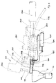
- the two side lasting assemblies are generally the same, save that one is a left-hand and the other a right-hand, and consequently only one of the assemblies will now be described with reference to Figs. 2 to 4; it will be appreciated that these Figures have been separated in order better to indicate features of the construction of the assembly.
- Each side lasting assembly 230 comprises a casting 32 which includes a pivotal mounting 34 by which the assembly 230 is supported on a frame portion of the machine for pivotal movement about a vertical axis whereby the operating elements of the assembly can be caused to move progressively in a direction lengthwise of the shoe bottom whereby, starting from the heel breast line region, a side lasting operation can be progressively effected along the sides of the shoe.
- a piston-and-cylinder arrangement (not shown but designated 38 in EP-A 0247831) is provided, also mounted on a frame portion of the machine, and having associated therewith a so-called "Hydrocheck" control unit by which the speed at which the operating elements are caused to move progressively along the shoe bottom can be controlled.
- the casting 32 is provided with a pivot pin (not shown, but designated 42 in EP-A 0247831), extending horizontally and normally to the direction of the axis of the mounting 34, for supporting a main support block of the assembly 230, the arrangement being such that the operating elements of said assembly can thus move heightwise of the bottom of a shoe supported by the shoe support.
- a piston-and-cylinder arrangement 46 is provided, mounted on the casting 32 and acting upon a rearward end portion of an extension rod projecting from the block.
- the main support block supports at its opposite end a piston-and-cylinder arrangement 250 having a piston rod 252 projecting forwardly therefrom (to the left viewing Fig. 2), said rod in turn supporting a block 254 at its forward end.
- a support block 256 Secured to one side of the block 254 is a support block 256 having a pivotal mounting 258 therein for a carrier 260, which is thus mounted for pivotal movement about the axis of said mounting 258.
- a piston-and-cylinder arrangement 262 is supported by the support block 256 for effecting such pivotal movement.
- the carrier 260 supports a fastener-inserting tool 64 (being of the same construction as the tack insertion device 5 described in EP-A0123471), said tool comprising a block 66 in which a fastener (tack) can be received along a supply tube 67 for driving into the shoe, and also in which the leading end of a driver rod 68 is accommodated for driving such fastener.
- the block 66 also provides a surface 70 which engages the over-wiped lasting marginal portion of the shoe upper to be secured by the fastener.
- the fastener-inserting tool 64 can pivot about the axis of the pivotal mounting 258 the block 66 can be oriented according to the contour of the shoe bottom, especially in the case of ladies high heeled shoes, it being of course desirable that the tacks are driven perpendicularly, or substantially so, into the shoe bottom.
- the wiper arrangement 274 comprises a so-called sleeking roll 276 which is generally cylindrical and is provided with a helical wiper element 282, together with means, including a motor (not shown) and a flexible drive shaft 278, for rotating the roll.
- each instrumentality 230 generally movable in a direction transversely of the shoe bottom to move the operating elements thereof from an initial, out-of-the-way, position into an operative position in which the fastener-inserting tools 64 overlie the marginal portions of the shoe bottom, this movement being achieved by the operation of the piston-and-cylinder arrangements 250.
- each instrumentality 230 also comprises a sensing finger 104 which is pivotally mounted on an extension of the block 66. The finger engages a side portion of the shoe and is thus cammed sideways about its pivot upon such engagement.
- the opposite end of the finger 104 constitutes an actuator for a microswitch (not shown, but designated 108 in EP-A 0123471) which, when actuated, generates a signal to terminate inward movement of the operating elements under the action of the piston-and-cylinder arrangement 250.
- a microswitch not shown, but designated 108 in EP-A 0123471
- a non-rotary finger 178 (omitted from Figs 1 and 2, but shown in Figs 3 and 4) which extends inwardly transversely of the shoe bottom and engages the lasting margin of the upper in advance of the roll 276 to afford a preliminary folding of said margin over the insole edge.
- the finger 178 is mounted, for adjustment as to its inclination both heightwise and widthwise of the shoe bottom, in a block 180 carried at one end of a bracket 182 itself supported for pivotal movement on the extension 259 of the support block 256.
- a piston-and-cylinder arrangement 184 is provided, also mounted on the extension 259 and acting on the bracket 182.
- the shoe support 10 is swung into its operative position, determined by engagement of the heel end of the shoe with the heel band 14, and further is moved heightwise to bring the heel seat region thereof into engagement with the holddown 20.
- the side lasting assemblies 230 are moved to their operative position, determined by engagement of the sensing fingers 104 with edges of the shoe bottom, thereby positioning both the sleeking rolls 276 and the fastener-inserting tools 64 in a correct relationship with the margins of the shoe bottom along which they are to operate progressively.
- the sensing fingers 104 are operative throughout the cycle of operation to position the tools 64 in the correct relationship with the marginal portions of the shoe bottom, following the contour thereof. It will also be appreciated that, as each assembly 230 moves inwardly as aforesaid, the non-rotary finger 178 thereof engages the lasting margin to perform a preliminary folding operation over the insole edge, and also the roll 276, which is at this time rotating, effects through its wiping element 282 an in-wiping action on the lasting margin and presses it against the insole margin. As can be seen from Fig. 3, the lasting roll operates "downstream" of the fastener- inserting tool 64, the direction of operation being from the heel breastline of the shoe bottom toewardly.
- the angle formed by the axis of each roll with the longitudinal centre line of the shoe bottom will vary along the length of the shoe and more specifically, the rolls will define arcs which correspond largely to the contour of the side portions of the shoe bottom.
- the axis of each thereof forms, with a line perpendicular to the longitudinal centre line of the operating locality of the machine, an angle of some 7.5°, while at the end position of each roll the angle formed with such line is in the order of 15°, the axis having at one stage passed through a position coincident with said line.
- material forming part of the lasting margin tends to be drawn not only inwardly over the insole edge but also toewardly in advance of the advancing rolls so that, by the end of such traverse, in some instances a fold F of material is created between the roll and the already lasted forepart portion of the shoe upper.
- the machine has various modes of operation which involve the axial displacement of a selected one or both of the rolls 276 by the action of the piston-and-cylinder arrangement(s) 284 associated therewith upon reaching a predetermined position in the course of their operation along the sides of the shoe bottom.
- each roll 276 is displaced axially inwardly relative to its associated fastener-inserting tool 64 over the insole edge to a position indicated in chain-dot line in Fig. 2 and thus effects an enhanced in-wiping movement on the lasting margin in that region by drawing the excess material further inwardly and thus effecting a desired material-spreading action.
- the rate at which the lasting rolls move along the side portions of the shoe bottom may be reduced during such axial displacement, in which case such displacement is initiated before the end position of the roll is reached.
- the axial displacement of the rolls may be effected when the end position is reached; that is to say, the movement of the lasting roll along the shoe bottom is arrested upon initiation of the axial displacement thereof.
- This axial inward displacement of each roll also serves to counter any tendency of the roll to run off the shoe bottom as a result of its arcuate path.
- a second mode of operation only one of the two lasting rolls 276 effects such inward axial displacement, more particularly the roll which operates along the "outside" side region of the shoe bottom.
- the axial displacement takes place at or adjacent the ball region of the shoe bottom, with the longitudinal movement either at reduced speed or arrested, as in the case of the first mode of operation.
- Such axial displacement again serves to ensure that the "outside” roll 276 remains in an appropriate relationship to the shoe bottom at the ball region, as well as effecting a material-spreading function.
- the two rolls 276 are displaced inwardly, but at different times in the operating cycle. More particularly the roll 276 operating on the "inside" side portion is displaced axially inwardly immediately upon the rolls 276 being brought into engagement with the shoe bottom, that is to say at the heel breastline region, in response to the sensing of the edge of the shoe by the sensing finger 104 as aforesaid. This axial displacement thus serves to effect an additional inwiping force to the lasting margin at said region prior to the insertion of the first tacks.
- the "outside” roll 276 is also displaced axially at a predetermined position in the waist region of the shoe, that is to say at a position reached somewhat earlier than in the case of the first and second modes. More particularly, bearing in mind that the rolls 276 are caused to pivot about a vertical axis to effect their longitudinal movement relative to the shoe bottom, as hereinfore described, the axial inward displacement of the "outside” roll 276 takes place as the rolls lie with their axes parallel to one another, that is to say at a position lying approximately one third of the way along the path of the rolls 276.
- the initial displacement of the "inside” roll 276 ensures that a tighter wrapping of the upper about the last in the breast line region, which in turn has the effect of ensuring that the whole of the "inside” side portion of the upper is so positioned in relation to the insole/shoe bottom that the risk of a fold being formed therein is signficantly diminished.
- the axial displacement is delayed until a position is reached whereat the material-spreading function can be effectively performed. In some cases, it has been found to be beneficial to effect this function before the roll reaches the ball region, thereby enabling the material to be spread over a broader area of the shoe bottom; in this way the formation of a fold at the ball region can thus be avoided.
- the machine also comprises control means whereby the various operations are caused to take place in sequence.
- a "start" button (not shown)
- the side lasting instrumentalities 230 are moved to their operative position, as described above, and a first tack is then inserted by the fastener-inserting tools 64, one at each side of the shoe upper in the region of the breastline thereof,in response to the sensing of the edge of the shoe by the sensing fingers 104.
- the arcuate movement of the side lasting assemblies is then initiated, and the fastener-inserting tools 64 are caused intermittently to insert tacks along the length of the side portions of the shoe.
- an operator-settable valve or microswitch (not shown) is associated with each side lasting assembly 230 so as to be actuatable by a portion of the latter as it is moved along its path.
- this valve or microswitch will be effective also to signal the piston-and-cylinder arrangement 284 to effect such inward displacement movement; where the axial inward displacement takes place before the end of the traverse of the rolls along the shoe bottom, a second valve or microswitch (also not shown) is provided for each side lasting assembly 230 and is similarly actuatable.
- This second valve or microswitch is also of course operator-settable, either independently of the first-mentioned valve or microswitch, or in common therewith.
- the arrangement of switches can similarly be provided for effecting inward axial displacement of the "outside" roll 276.
- control means may include any suitable means such as has been proposed for sensing whether a shoe being operated upon is a left or a right; for example, bearing in mind that the shoe will be centralised, or substantially so, with its longitudinal centre line aligned with the longitudinal centre line of the heel seat lasting instrumentalities, the offset of the toe portion may be sensed, whether by positional sensors or by sensors montoring the position of the toe rest 18, which can pivot about a heightwise axis through a limited arc to accommodate left and right shoes.
- a simple operator-actuatable left/right switching arrangement such as is described in GB-A 2126870 may be used; this arrangement may of course also be used for pivoting the toe rest 18 under power between "left shoe” and “right shoe” supporting positions.
- the inward axial displacement of the "inside” roll 276 is caused to take place upon actuation of its associated sensing finger 104.
- a third operator-settable valve or microswitch (not shown, but similar to the second such valve or microswitch provided for the first mode) is provided, located so as to be actuated at the appropriate time in the machine cyle.
- each roll may have a second and a third such valve or microswitch associated therewith, means being provided in the control means for rendering the appropriate valve active and the other inactive.
- the invention is equally applicable to so-called cement side lasting machines where the lasting rolls 276 are effective also to secure the lasting margin to the insole margin by pressing, using previously applied adhesive.
- the invention is applicable to side lasting machines as well as combination side and seat lasting machines; it is also applicable in its broader aspects to combination toe and side lasting machines, especially where the heel seat region of the shoe has been lasted prior to presentation to such combination machine.
Landscapes
- Footwear And Its Accessory, Manufacturing Method And Apparatuses (AREA)
- Paper (AREA)
Claims (10)
- Machine de montage des parties latérales des empeignes de chaussures, comprenant
un support (10) d'une chaussure, avec la semelle vers le haut, la chaussure comprenant une empeigne placée sur une forme avec une première disposée sur le fond de la forme,
des accessoires de montage des côtés comprenant deux ensembles de rabattement (230) placés chacun d'un côté du support (10) de chaussure et comprenant chacun un rouleau rotatif de montage (276) disposé transversalement à la semelle de la chaussure et ayant un élément hélicoïdal de rabattement (282) qui est au contact de l'empeigne pour appliquer une force de rabattement vers l'intérieur à l'empeigne lorsque le rouleau tourne, avec un dispositif (278) destiné à assurer la rotation des rouleaux (276), et
un dispositif destiné à assurer un déplacement relatif, suivant la longueur de la semelle de la chaussure, entre le support (10) de la chaussure et les accessoires de montage des côtés de manière que les rouleaux de montage (276) travaillent progressivement le long des parties latérales opposées de la semelle de la chaussure,
caractérisé en ce que l'un au moins des rouleaux de montage (276), lorsqu'il a atteint une région prédéterminée en travaillant progressivement le long de la semelle de la chaussure comme indiqué précédemment, se déplace axialement vers l'intérieur, vers l'autre rouleau (276). - Machine selon la revendication 1, caractérisée en ce que le premier rouleau (276) qui est déplacé axialement vers l'intérieur comme indiqué est constitué par le rouleau travaillant sur la marge externe de la semelle de la chaussure, la disposition étant telle qu'il est déplacé axialement de cette manière lorsqu'il atteint la région de l'éminence métatarsienne sur la semelle de la chaussure.
- Machine selon la revendication 2, caractérisée en ce que les deux rouleaux (276) sont déplacés axialement comme indiqué lorsqu'ils atteignent la région de l'éminence métatarsienne sur la semelle de la chaussure.
- Machine selon l'une quelconque des revendications précédentes, caractérisée en ce que la vitesse de déplacement relatif du support de la chaussure et des accessoires de montage des côtés est réduite lorsque le mouvement de déplacement vers l'intérieur du rouleau de montage ou de chaque rouleau de montage est réalisé comme indiqué précédemment.
- Machine selon l'une des revendications 1 et 2, caractérisée en ce que le mouvement relatif du support de chaussure et des accessoires de montage des côtés est interrompu lorsque le déplacement vers l'intérieur du rouleau de montage ou de chaque rouleau de montage est réalisé comme indiqué.
- Machine selon la revendication 1, caractérisée en ce que le rouleau (276) qui est déplacé axialement vers l'intérieur comme indiqué est constitué par le rouleau qui travaille sur la marge externe de la semelle de la chaussure, la disposition étant telle qu'il est déplacé axialement lorsqu'il atteint la région rétrécie de la semelle de la chaussure.
- Machine selon la revendication 6, dans laquelle les rouleaux de montage (276) sont montés afin qu'ils puissent pivoter autour d'un axe dirigé suivant la hauteur et qu'ils se déplacent suivant la longueur de la semelle de la chaussure par rapport au support (10) de la chaussure, si bien que les rouleaux (276) travaillent progressivement le long des parties marginales opposées de la semelle de la chaussure comme indiqué précédemment, et dans laquelle l'axe de chaque rouleau (276), lorsqu'il pivote, passe par une position qui coïncide avec une perpendiculaire à l'axe central longitudinal de l'emplacement de travail de la machine, caractérisée en ce que le rouleau (276) est déplacé axialement comme indiqué précédemment lorsqu'il atteint la position précitée.
- Machine selon l'une des revendications 6 et 7, caractérisée en ce que l'autre rouleau (276) qui travaille le long de la marge interne de la semelle de la chaussure est aussi déplacé axialement vers l'intérieur lorsqu'il a été mis au contact de la semelle de la chaussure.
- Machine selon la revendication 8, dans laquelle un doigt (104) de détection est associé à chaque rouleau (276) et, après détection du bord de la semelle de la chaussure par contact avec lui lorsque le rouleau (276) se déplace vers la position de travail, il assure l'arrêt de ce déplacement et détermine la position de travail, caractérisée en ce que, à la suite de la détection du bord de la semelle de la chaussure par le doigt (104) de détection, le rouleau interne (276) est déplacé axialement vers l'intérieur comme indiqué.
- Machine selon l'une quelconque des revendications précédentes, dans laquelle les accessoires de montage des côtés comportent deux outils (64) d'introduction d'organes de fixation, associés chacun à un rouleau de montage (276), chaque rouleau (276) et d'outil associé (64) étant mobiles ensemble en direction transversale à la semelle de la chaussure de manière qu'ils suivent le contour de la semelle de la chaussure, caractérisée en ce que, dans le mouvement de déplacement axial, le rouleau ou chaque rouleau (276) se déplace vers l'intérieur par rapport à l'outil associé (64).
Applications Claiming Priority (2)
| Application Number | Priority Date | Filing Date | Title |
|---|---|---|---|
| DE3642239 | 1986-12-10 | ||
| DE19863642239 DE3642239A1 (de) | 1986-12-10 | 1986-12-10 | Verfahren und vorrichtung zum zwicken eines schuhschaftes |
Publications (3)
| Publication Number | Publication Date |
|---|---|
| EP0271303A2 EP0271303A2 (fr) | 1988-06-15 |
| EP0271303A3 EP0271303A3 (en) | 1989-07-05 |
| EP0271303B1 true EP0271303B1 (fr) | 1992-03-25 |
Family
ID=6315911
Family Applications (1)
| Application Number | Title | Priority Date | Filing Date |
|---|---|---|---|
| EP87310729A Expired - Lifetime EP0271303B1 (fr) | 1986-12-10 | 1987-12-07 | Machine pour le montage des côtés de dessus de chaussures |
Country Status (5)
| Country | Link |
|---|---|
| US (1) | US4853997A (fr) |
| EP (1) | EP0271303B1 (fr) |
| JP (1) | JPS63214201A (fr) |
| DE (2) | DE3642239A1 (fr) |
| ES (1) | ES2031522T3 (fr) |
Families Citing this family (6)
| Publication number | Priority date | Publication date | Assignee | Title |
|---|---|---|---|---|
| DE3906733A1 (de) * | 1989-03-03 | 1990-09-06 | Schoen & Cie Gmbh | Schuhzwickmaschine |
| GB8927902D0 (en) * | 1989-12-09 | 1990-02-14 | British United Shoe Machinery | Machine for lasting side portions of shoe uppers |
| IT1239938B (it) * | 1990-04-03 | 1993-11-23 | Ormac | Dispositivo per chiudere,stirare ed inchiodare i fianchi di una tomaiaad un rispettivo sottopiede, in particolare per macchine montatrici diparti di calzatura |
| GB9109270D0 (en) * | 1991-04-30 | 1991-06-19 | British United Shoe Machinery | Machine for lasting side portions of shoe uppers |
| GB9109271D0 (en) * | 1991-04-30 | 1991-06-19 | British United Shoe Machinery | Shoe support and machine for use in the manufacture of shoes |
| CA2473611C (fr) * | 2002-02-22 | 2010-03-16 | Dow Global Technologies Inc. | Mousse insonorisante macrocellulaire contenant un additif particulaire |
Family Cites Families (13)
| Publication number | Priority date | Publication date | Assignee | Title |
|---|---|---|---|---|
| DE1817915C3 (de) * | 1968-12-03 | 1975-10-30 | Deutsche Vereinigte Schuhmaschinen Gmbh, 6000 Frankfurt | Vorrichtung zum Ankleben des Zwickeinschlages an der Brandsohle von fest eingespanntem Schuhwerk |
| DE1909474A1 (de) * | 1969-02-25 | 1970-09-10 | Ver Schuhmasch Gmbh | Vorrichtung zum Bearbeiten des Randes von festeingespanntem Schuhwerk |
| DE2233331A1 (de) * | 1972-07-06 | 1974-01-24 | Eugen G Henkel Maschinenfabrik | Maschine zum zwicken von schuhwerk |
| GB1493937A (en) * | 1974-05-07 | 1977-11-30 | British United Shoe Machinery | Shoe upper conforming machines |
| DE7539113U (de) * | 1975-12-08 | 1976-06-03 | Deutsche Vereinigte Schuhmaschinen Gmbh, 6000 Frankfurt | Vorrichtung zum klebezwicken von fest eingespanntem schuhwerk |
| DE2845303C2 (de) * | 1978-10-18 | 1986-03-06 | Schön & Cie GmbH, 6780 Pirmasens | Vorrichtung zum Andrücken des Schaftrandes an die Brandsohle einer Schuheinheit |
| DE2917552A1 (de) * | 1979-04-30 | 1980-11-13 | Ver Schuhmasch Gmbh | Verfahren und vorrichtung zum zwicken von schuhwerk |
| GB2052950B (en) * | 1979-07-16 | 1983-02-16 | British United Shoe Machinery | Machine for lasting heel seat portions of shoes |
| EP0050026A3 (fr) * | 1980-10-11 | 1984-04-18 | British United Shoe Machinery Limited | Machine à monter les tiges de chaussure |
| GB2126870B (en) * | 1982-09-11 | 1985-10-02 | British United Shoe Machinery | Side lasting machines |
| US4491997A (en) * | 1983-03-21 | 1985-01-08 | Usm Corporation | Machine for lasting heel seat portions of shoes |
| DE3314906A1 (de) * | 1983-04-25 | 1984-10-25 | Deutsche Vereinigte Schuhmaschinen Gmbh, 6000 Frankfurt | Verfahren und vorrichtung zum seitenzwicken von aufgeleisteten schuhen mit einer seiten-tacks-einschlagvorrichtung |
| GB8612800D0 (en) * | 1986-05-27 | 1986-07-02 | Busm Co Ltd | Side & heel seat lasting machine |
-
1986
- 1986-12-10 DE DE19863642239 patent/DE3642239A1/de not_active Withdrawn
-
1987
- 1987-12-07 ES ES198787310729T patent/ES2031522T3/es not_active Expired - Lifetime
- 1987-12-07 DE DE8787310729T patent/DE3777771D1/de not_active Expired - Fee Related
- 1987-12-07 EP EP87310729A patent/EP0271303B1/fr not_active Expired - Lifetime
- 1987-12-09 JP JP62311806A patent/JPS63214201A/ja active Pending
-
1988
- 1988-12-28 US US07/290,874 patent/US4853997A/en not_active Expired - Fee Related
Also Published As
| Publication number | Publication date |
|---|---|
| DE3642239A1 (de) | 1988-06-23 |
| DE3777771D1 (de) | 1992-04-30 |
| ES2031522T3 (es) | 1992-12-16 |
| EP0271303A2 (fr) | 1988-06-15 |
| EP0271303A3 (en) | 1989-07-05 |
| US4853997A (en) | 1989-08-08 |
| JPS63214201A (ja) | 1988-09-06 |
Similar Documents
| Publication | Publication Date | Title |
|---|---|---|
| EP0271303B1 (fr) | Machine pour le montage des côtés de dessus de chaussures | |
| US3868737A (en) | Method and apparatus for combined lasting of the toe, ball and shank areas of shoes | |
| CA1127806A (fr) | Machine a monter les chaussures | |
| EP0457882B1 (fr) | Machine de mise sur la forme des parties laterales de tiges de souliers | |
| US4407033A (en) | Combination toe and side lasting machine | |
| US4491997A (en) | Machine for lasting heel seat portions of shoes | |
| EP0118243B1 (fr) | Montage de chaussures utilisant un adhésif | |
| US4467487A (en) | Shoe upper conforming machine | |
| EP0353881B1 (fr) | Machine destinée à travailler progressivement le long des parties marginales des chaussures | |
| US3894670A (en) | Shoe upper fastening device | |
| EP0247831B1 (fr) | Machine à Monter les Flancs et les Emboitages | |
| EP0091299B1 (fr) | Machine à rabattre les talons de chaussures | |
| US4377876A (en) | Shoe lasting machine | |
| US4436771A (en) | Method of lasting shoes | |
| US4435869A (en) | Shoe lasting machines | |
| US4404700A (en) | Machine for lasting side portions of shoes | |
| GB2126870A (en) | Side lasting machines | |
| US3906568A (en) | Band wiping mechanism for shoe lasting machine | |
| US1722499A (en) | Lasting machine | |
| US2238922A (en) | Prewelt straightening and cementing machine | |
| US1142152A (en) | Holddown for lasting-machines. | |
| US1614836A (en) | Machine for operating on boots and shoes | |
| US4442563A (en) | Shoe lasting machine | |
| GB2091535A (en) | Automatically controlling shoe machinery as a lasted assembly is conveyed therethrough | |
| EP0756463A1 (fr) | Machine de montage des parties laterales de tiges de chaussures |
Legal Events
| Date | Code | Title | Description |
|---|---|---|---|
| PUAI | Public reference made under article 153(3) epc to a published international application that has entered the european phase |
Free format text: ORIGINAL CODE: 0009012 |
|
| AK | Designated contracting states |
Kind code of ref document: A2 Designated state(s): DE ES FR GB IT |
|
| PUAL | Search report despatched |
Free format text: ORIGINAL CODE: 0009013 |
|
| AK | Designated contracting states |
Kind code of ref document: A3 Designated state(s): DE ES FR GB IT |
|
| 17P | Request for examination filed |
Effective date: 19891213 |
|
| 17Q | First examination report despatched |
Effective date: 19910614 |
|
| GRAA | (expected) grant |
Free format text: ORIGINAL CODE: 0009210 |
|
| AK | Designated contracting states |
Kind code of ref document: B1 Designated state(s): DE ES FR GB IT |
|
| ET | Fr: translation filed | ||
| REF | Corresponds to: |
Ref document number: 3777771 Country of ref document: DE Date of ref document: 19920430 |
|
| ITF | It: translation for a ep patent filed | ||
| PGFP | Annual fee paid to national office [announced via postgrant information from national office to epo] |
Ref country code: ES Payment date: 19921204 Year of fee payment: 6 |
|
| PG25 | Lapsed in a contracting state [announced via postgrant information from national office to epo] |
Ref country code: GB Effective date: 19921207 |
|
| REG | Reference to a national code |
Ref country code: ES Ref legal event code: FG2A Ref document number: 2031522 Country of ref document: ES Kind code of ref document: T3 |
|
| ITTA | It: last paid annual fee | ||
| PLBE | No opposition filed within time limit |
Free format text: ORIGINAL CODE: 0009261 |
|
| STAA | Information on the status of an ep patent application or granted ep patent |
Free format text: STATUS: NO OPPOSITION FILED WITHIN TIME LIMIT |
|
| 26N | No opposition filed | ||
| GBPC | Gb: european patent ceased through non-payment of renewal fee |
Effective date: 19921207 |
|
| PGFP | Annual fee paid to national office [announced via postgrant information from national office to epo] |
Ref country code: FR Payment date: 19931109 Year of fee payment: 7 |
|
| PG25 | Lapsed in a contracting state [announced via postgrant information from national office to epo] |
Ref country code: ES Free format text: LAPSE BECAUSE OF NON-PAYMENT OF DUE FEES Effective date: 19941208 |
|
| PG25 | Lapsed in a contracting state [announced via postgrant information from national office to epo] |
Ref country code: FR Effective date: 19950831 |
|
| REG | Reference to a national code |
Ref country code: FR Ref legal event code: ST |
|
| PGFP | Annual fee paid to national office [announced via postgrant information from national office to epo] |
Ref country code: DE Payment date: 19961122 Year of fee payment: 10 |
|
| PG25 | Lapsed in a contracting state [announced via postgrant information from national office to epo] |
Ref country code: DE Free format text: LAPSE BECAUSE OF NON-PAYMENT OF DUE FEES Effective date: 19981201 |
|
| REG | Reference to a national code |
Ref country code: ES Ref legal event code: FD2A Effective date: 19950112 |
|
| PG25 | Lapsed in a contracting state [announced via postgrant information from national office to epo] |
Ref country code: IT Free format text: LAPSE BECAUSE OF NON-PAYMENT OF DUE FEES;WARNING: LAPSES OF ITALIAN PATENTS WITH EFFECTIVE DATE BEFORE 2007 MAY HAVE OCCURRED AT ANY TIME BEFORE 2007. THE CORRECT EFFECTIVE DATE MAY BE DIFFERENT FROM THE ONE RECORDED. Effective date: 20051207 |