EP0271384A1 - Einrichtung zur Zirkulation eines Schmiermittels in einem Schmierungskreislauf einer Brennkraftmaschine - Google Patents
Einrichtung zur Zirkulation eines Schmiermittels in einem Schmierungskreislauf einer Brennkraftmaschine Download PDFInfo
- Publication number
- EP0271384A1 EP0271384A1 EP87402559A EP87402559A EP0271384A1 EP 0271384 A1 EP0271384 A1 EP 0271384A1 EP 87402559 A EP87402559 A EP 87402559A EP 87402559 A EP87402559 A EP 87402559A EP 0271384 A1 EP0271384 A1 EP 0271384A1
- Authority
- EP
- European Patent Office
- Prior art keywords
- pump
- chamber
- bore
- engine
- gear
- Prior art date
- Legal status (The legal status is an assumption and is not a legal conclusion. Google has not performed a legal analysis and makes no representation as to the accuracy of the status listed.)
- Granted
Links
- 238000005461 lubrication Methods 0.000 title claims abstract description 17
- 238000002485 combustion reaction Methods 0.000 title claims abstract description 9
- 239000000314 lubricant Substances 0.000 title claims abstract description 7
- 230000008021 deposition Effects 0.000 claims description 4
- 238000007650 screen-printing Methods 0.000 claims description 4
- 229920001296 polysiloxane Polymers 0.000 claims description 3
- 239000003566 sealing material Substances 0.000 claims 2
- 230000001815 facial effect Effects 0.000 description 2
- 238000003754 machining Methods 0.000 description 2
- 230000000694 effects Effects 0.000 description 1
- 239000000463 material Substances 0.000 description 1
- 230000002093 peripheral effect Effects 0.000 description 1
- 238000007789 sealing Methods 0.000 description 1
Images

Classifications
-
- F—MECHANICAL ENGINEERING; LIGHTING; HEATING; WEAPONS; BLASTING
- F01—MACHINES OR ENGINES IN GENERAL; ENGINE PLANTS IN GENERAL; STEAM ENGINES
- F01M—LUBRICATING OF MACHINES OR ENGINES IN GENERAL; LUBRICATING INTERNAL COMBUSTION ENGINES; CRANKCASE VENTILATING
- F01M1/00—Pressure lubrication
- F01M1/02—Pressure lubrication using lubricating pumps
-
- F—MECHANICAL ENGINEERING; LIGHTING; HEATING; WEAPONS; BLASTING
- F16—ENGINEERING ELEMENTS AND UNITS; GENERAL MEASURES FOR PRODUCING AND MAINTAINING EFFECTIVE FUNCTIONING OF MACHINES OR INSTALLATIONS; THERMAL INSULATION IN GENERAL
- F16J—PISTONS; CYLINDERS; SEALINGS
- F16J15/00—Sealings
- F16J15/02—Sealings between relatively-stationary surfaces
- F16J15/14—Sealings between relatively-stationary surfaces by means of granular or plastic material, or fluid
Definitions
- the invention relates to a device ensuring the circulation of a lubricant in a lubrication circuit of an internal combustion engine comprising a gear pump having a body attached to a part of the engine.
- a gear pump of such a motor lubrication device comprises two pinions which mesh with each other and which are mounted rititically inside a chamber formed by two intersecting bores and two opposite median zones intersecting the bores in their common part on either side of the plane containing their axes.
- the gears are each mounted in a bore of the chamber with its axis of rotation along the axis of the bore.
- the pump chamber is delimited by two faces perpendicular to the axes of the bores and the pinions and the two median zones open on one of these faces so as to be in the extension of two corresponding conduits of the lubrication circuit constituting respectively a suction pipe and an oil delivery pipe.
- One of the pinions is integral with a shaft on which is fixed a means for driving the pinion in rotation.
- the pump body enclosing the chamber and the two pinions. It is thus possible, by providing a pump body and a set of gears specially produced, to have for each type of motor the desired oil flow rate.
- the body of the pump has a through bearing for the drive shaft and encloses the chamber in which the two pinions are mounted.
- the pump body comes into contact with the part of the motor via a flat surface of this part on which the suction and discharge conduits open. This flat face of the motor part also constitutes one of the faces delimiting the pump chamber.
- the pump is fixed to the motor part by screws passing through radial extensions of the body.
- a pump is known, the chamber of which is produced in a cylindrical part fitted into a blind bore of the body whose axis is parallel to the axis of the pinions.
- the pump chamber is delimited, opposite the plane bearing surface of the engine part, by the bottom of the blind bore of the body.
- An annular face seal is inserted between the body and the bearing face of the engine part.
- the object of the invention is therefore to propose a device ensuring the circulation of a lubricant in a lubrication circuit of an internal combustion engine comprising a gear pump having a body attached to a part of the engine along a flat surface of this part onto which at least two conduits of the lubrication circuit lead, the body enclosing a chamber consisting of two intersecting bores with parallel axes in each of which a gear is mounted to rotate around the axis of the bore and two median zones intersecting the bores in their common part, on either side of the gears, and emerging, each in the extension of a lubrication duct, at the level of the flat surface of the engine part constituting a face limiting the chamber perpendicular to the axes of the bores , one of the gears being connected to a rotational drive means and meshing with the other gear, a device which is of reduced bulk and great ease of assembly.
- the engine part has a blind bore, the bottom of which constitutes the flat surface on which the lubrication conduits open and the pump body has a part externally limited by a cylindrical surface surrounding the chamber whose axis is parallel. to the axis of the bores of the chamber, this part being housed in the blind bore of the motor part, in sealed contact with this bore in a continuous zone surrounding the chamber and the fixing of the pump body on the part of the motor being provided by screws passing through its cylindrical part, in axial directions and engaged in threaded holes in the part of the motor.
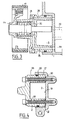
- FIG 1 we see a part 1 of the cylinder block of an internal combustion engine in which is housed the corpos 2 of a gear pump.
- This body 2 contains a chamber 3 consisting of two intersecting bores 4 and 5 with parallel axes and two median zones 6 and 7 intersecting the bores 4 and 5, in the vicinity of their common part, on either side of the plane containing the bore axes.
- gears 8 and 9 meshing with one another are mounted respectively in the bores 4 and 5, on respective shafts 10 and 11 arranged along the axis of the bore corresponding.
- the shaft 10 on which the gear 8 is mounted is a drive shaft rotatably mounted in a ball bearing 12, so that its end opposite to the gear 8 is located outside the body 2 of the pump .
- this end of the shaft 10 is integral with a pulley 14 over which passes a belt 15 ensuring the drive of the shaft 10 and of the pinion 8 in rotation, from the crankshaft of the engine.
- This belt 15 can advantageously consist of the engine timing belt.
- the end of the shaft 10 engaged in a central bore of the pinion 8 comprises a machining along a half-section which is engaged in a corresponding part of the bore of the pinion 8.
- the shaft 10 and the pinion 8 are thus integral in rotation.
- the shaft 11, on which the pinion 9 is rotatably mounted, is fitted into a blind bore of the body 2 of the pump.
- the chamber 3 of the pump is machined directly inside the body 2 and has a flat face 3a perpendicular to the axes of the bores and the pinions formed inside the body 2.
- the opposite face 3b of the chamber 3 is constituted by an outer flat surface of the cylinder block 1.
- the gears 8 and 9 are mounted to rotate with a small radial clearance inside the bores 4 and 5.
- the cylinder casing 1 has a blind bore 17, the bottom 18 of which constitutes the plane bearing surface of the body 2 of the pump and the face 3b for closing the chamber 3. Through this bottom 18, open two conduits such as the conduit 20 visible in FIGS. 2 and 3. One of the two conduits constitutes a suction conduit and the other a discharge conduit of the engine lubrication circuit.
- the body 2 of the pump has a part 21 externally limited by a cylindrical surface surrounding the chamber 3, the axis of which is parallel to the axis of the bores 4 and 5 and therefore to the axis of rotation of the pinions 8 and 9.
- This cylindrical part 21 has a diameter very slightly less than the diameter of the blind bore 17 of the cylinder block 1.
- the part 21 of the body 2 is engaged in the blind bore 17 so that the end of the body 2 comes to bear against the bottom 18 of this blind bore.
- the median zones 6 and 7 of the chamber 3 each come in the extension of a conduit 20.
- the direction of rotation of the gears 8 and 9 of the pump makes it possible to distinguish a suction zone and a discharge zone in the chamber 3 which are placed in communication respectively with the suction conduit and with the discharge conduit passing through the bottom 18 of the blind bore. 17.
- the cylindrical part 21 of the body 2 of the pump has, on its peripheral surface, a groove 24 into which a seal 25 is introduced.
- This seal 25 seals between the body 21 and the bore 17, in a continuous zone located all around room 3.
- the chamber 3 is sealed around the drive shaft 10 by a seal 26 integrated into the ball bearing 12 of the shaft 10.
- the body 2 of the pump is fixed to the cylinder block 1 by means of screws 28 passing through this body in bores 29 of axial direction, at the level of the cylindrical part 21.
- the ends screws are engaged in threaded holes machined in the bottom 18 of the blind bore 17 of the cylinder block 1.
- annular seal 30 facial seal.
- This seal can in particular be produced in the form of a silicone ring deposited by screen printing on one of the contacting faces, that is to say the end face of the body 2 of the pump or the bottom 18 of the bore 17 of the cylinder block 1.
- annular chamber 32 is machined in the pump body 2, around the passage hole of the shaft 10, between the bearing 12 and the chamber 3.
- This annular chamber 32 constitutes a vacuum chamber between the internal chamber of the pump and the bearing of the drive shaft provided with its seal 26.
- Two channels 35 and 36 open into the chamber 32 to put this chamber in communication with the internal compartment 34 of the cylinder block 1.
- the channel 35 allows the return of internal leaks from the pump to the internal compartment of the engine and the channel 36 makes it possible to balance the pressures between the chamber 32 and the compartment 34 of the engine.
- the pump is fixed to the cylinder block 1, by means of the screws 28, so that the chamber 3 is completely sealed and that no oil leakage can occur towards the outside. This seal is obtained at the same time by the seal 25, the seals 30 of the screws and the seal 26 of the drive shaft 10.
- the fixing by the screws 28 passing through the cylindrical part 21 of the pump body 2 in the axial direction makes it possible to limit the total radial size of the pump.
- the fixing means are contained inside the cylindrical surface constituting the outer casing of the pump body 2 and the inner surface of the bore 17 of the cylinder block 1.
- the mounting of the pump is a very easy to make since this pump is perfectly engaged by its part 21 in the bore 17 and the heads of the screws 28 are perfectly accessible on the front face of the pump.
- the seal around the chamber 3 can be achieved by an O-ring engaged in a groove machined inside the blind bore 17.
- This seal could also be achieved by a seal deposited on the face d support of the body 2 of the pump or on the bottom 18 of the bore 17 constituting a continuous zone around the chamber 3.
- Such a face seal can be produced by deposition by screen printing of silicone in the desired area.
- the deposition by screen printing of the material constituting the seal could be extended to the entire bearing surface of the body 2 of the pump, around the chamber 3 and the screws 28.
- the lubricant circulation device according to the invention can be applied to any type of engine comprising a lubrication circuit.
Landscapes
- Engineering & Computer Science (AREA)
- General Engineering & Computer Science (AREA)
- Mechanical Engineering (AREA)
- Rotary Pumps (AREA)
Applications Claiming Priority (2)
| Application Number | Priority Date | Filing Date | Title |
|---|---|---|---|
| FR8617141A FR2607867B1 (fr) | 1986-12-08 | 1986-12-08 | Dispositif assurant la circulation d'un lubrifiant dans un circuit de lubrification d'un moteur a combustion interne |
| FR8617141 | 1986-12-08 |
Publications (2)
| Publication Number | Publication Date |
|---|---|
| EP0271384A1 true EP0271384A1 (de) | 1988-06-15 |
| EP0271384B1 EP0271384B1 (de) | 1990-01-24 |
Family
ID=9341662
Family Applications (1)
| Application Number | Title | Priority Date | Filing Date |
|---|---|---|---|
| EP19870402559 Expired - Lifetime EP0271384B1 (de) | 1986-12-08 | 1987-11-12 | Einrichtung zur Zirkulation eines Schmiermittels in einem Schmierungskreislauf einer Brennkraftmaschine |
Country Status (3)
| Country | Link |
|---|---|
| EP (1) | EP0271384B1 (de) |
| DE (1) | DE3761494D1 (de) |
| FR (1) | FR2607867B1 (de) |
Cited By (4)
| Publication number | Priority date | Publication date | Assignee | Title |
|---|---|---|---|---|
| FR2683262A1 (fr) * | 1991-11-06 | 1993-05-07 | Smh Management Services Ag | Moteur a combustion interne avec pompe a huile sur l'arbre a cames. |
| GB2365927A (en) * | 2000-08-15 | 2002-02-27 | Sauer Danfoss Swindon Ltd | Axially compact gear pump |
| GB2377741A (en) * | 2001-05-30 | 2003-01-22 | Systematic Drill Head Co Ltd | Gearbox |
| CN110761997A (zh) * | 2019-10-28 | 2020-02-07 | 无锡博伊特科技股份有限公司 | 微磁力齿轮循环泵 |
Families Citing this family (2)
| Publication number | Priority date | Publication date | Assignee | Title |
|---|---|---|---|---|
| RU2133349C1 (ru) * | 1997-12-24 | 1999-07-20 | Дронов Евгений Анатольевич | Двигатель внутреннего сгорания |
| RU210819U1 (ru) * | 2022-01-07 | 2022-05-05 | Акционерное общество "Ремдизель" | Масляный насос двигателя внутреннего сгорания |
Citations (5)
| Publication number | Priority date | Publication date | Assignee | Title |
|---|---|---|---|---|
| DE313021C (de) * | ||||
| FR2349773A1 (fr) * | 1976-04-30 | 1977-11-25 | Dowty Seals Ltd | Perfectionnements a des joints d'etancheite |
| GB2027807A (en) * | 1978-08-17 | 1980-02-27 | Maschf Augsburg Nuernberg Ag | Oil pump of an internal combustion engine |
| FR2456235A1 (fr) * | 1979-05-09 | 1980-12-05 | Nordson Corp | Pompe a cartouche |
| EP0161421A2 (de) * | 1984-03-19 | 1985-11-21 | Schwäbische Hüttenwerke Gesellschaft mit beschränkter Haftung | Innenläuferzahnradölpumpe für Kraftfahrzeugverbrennungsmotoren |
-
1986
- 1986-12-08 FR FR8617141A patent/FR2607867B1/fr not_active Expired - Fee Related
-
1987
- 1987-11-12 DE DE8787402559T patent/DE3761494D1/de not_active Expired - Fee Related
- 1987-11-12 EP EP19870402559 patent/EP0271384B1/de not_active Expired - Lifetime
Patent Citations (5)
| Publication number | Priority date | Publication date | Assignee | Title |
|---|---|---|---|---|
| DE313021C (de) * | ||||
| FR2349773A1 (fr) * | 1976-04-30 | 1977-11-25 | Dowty Seals Ltd | Perfectionnements a des joints d'etancheite |
| GB2027807A (en) * | 1978-08-17 | 1980-02-27 | Maschf Augsburg Nuernberg Ag | Oil pump of an internal combustion engine |
| FR2456235A1 (fr) * | 1979-05-09 | 1980-12-05 | Nordson Corp | Pompe a cartouche |
| EP0161421A2 (de) * | 1984-03-19 | 1985-11-21 | Schwäbische Hüttenwerke Gesellschaft mit beschränkter Haftung | Innenläuferzahnradölpumpe für Kraftfahrzeugverbrennungsmotoren |
Cited By (9)
| Publication number | Priority date | Publication date | Assignee | Title |
|---|---|---|---|---|
| FR2683262A1 (fr) * | 1991-11-06 | 1993-05-07 | Smh Management Services Ag | Moteur a combustion interne avec pompe a huile sur l'arbre a cames. |
| EP0540977A1 (de) * | 1991-11-06 | 1993-05-12 | SMH Management Services AG | Brennkraftmaschine mit Schmierpumpen auf der Nockenwelle |
| US5295463A (en) * | 1991-11-06 | 1994-03-22 | Smh Management Services Ag | Internal combustion engine with oil pump mounted on the camshaft |
| AU655387B2 (en) * | 1991-11-06 | 1994-12-15 | Smh Management Services Ag | Internal combustion engine with oil pump mounted on the camshaft |
| GB2365927A (en) * | 2000-08-15 | 2002-02-27 | Sauer Danfoss Swindon Ltd | Axially compact gear pump |
| GB2365927B (en) * | 2000-08-15 | 2002-10-30 | Sauer Danfoss Swindon Ltd | Axially compact gear pump |
| GB2377741A (en) * | 2001-05-30 | 2003-01-22 | Systematic Drill Head Co Ltd | Gearbox |
| CN110761997A (zh) * | 2019-10-28 | 2020-02-07 | 无锡博伊特科技股份有限公司 | 微磁力齿轮循环泵 |
| CN110761997B (zh) * | 2019-10-28 | 2024-05-03 | 无锡博伊特科技股份有限公司 | 微磁力齿轮循环泵 |
Also Published As
| Publication number | Publication date |
|---|---|
| FR2607867A1 (fr) | 1988-06-10 |
| DE3761494D1 (de) | 1990-03-01 |
| FR2607867B1 (fr) | 1991-01-11 |
| EP0271384B1 (de) | 1990-01-24 |
Similar Documents
| Publication | Publication Date | Title |
|---|---|---|
| FR2522736A1 (fr) | Systeme de lubrification du type brouillard auto-nettoyant a simple boucle pour compresseur a vis | |
| CA2621837C (fr) | Systeme de deshuilage pour moteur d'aeronef | |
| FR2508133A1 (fr) | Mecanisme de transmission a changement de rapport | |
| EP2582922B1 (de) | Führungs- und dichtungsvorrichtung für einen turbinemotor mit kohledichtung und integriertem traglager | |
| FR2468009A1 (fr) | Pompe et/ou moteur a engrenages | |
| EP0271384B1 (de) | Einrichtung zur Zirkulation eines Schmiermittels in einem Schmierungskreislauf einer Brennkraftmaschine | |
| EP0540977B1 (de) | Brennkraftmaschine mit Schmierpumpen auf der Nockenwelle | |
| EP1280996A1 (de) | Dosierpumpe zum fördern von flüssigkeiten | |
| FR2798428A1 (fr) | Boite de vitesses , par exemple pour vehicule automobile , a commande hydraulique , plateaux de commande , et couche intermediaire. | |
| FR2518200A1 (fr) | Appareil pour l'alimentation en fluide d'un embrayage hydraulique | |
| EP4023909B1 (de) | Satellitenträger für ein reduktionsgetriebe für luftfahrzeug-turbotriebwerk | |
| FR2545193A1 (fr) | Boitier amovible de distribution pour moteur a explosion ou a combustion | |
| FR2746447A1 (fr) | Installation pour transferer du carburant d'un reservoir vers le moteur d'un vehicule automobile, par une pompe a engrenages ou a transfert et une pompe a cellules semi-rotative | |
| EP1186802A1 (de) | Antriebsvorrichtung mit Hydraulikmotor und Zahnradgetriebe | |
| FR2491171A3 (fr) | Dispositif tournant de pompage capable de supporter un element tournant tout en debitant un liquide ayant des proprietes lubrifiantes | |
| CA2138356A1 (fr) | Systeme de pompage comportant une pompe volumetrique a grand debit | |
| FR2619881A1 (fr) | Arbre d'equilibrage pour moteur a pistons alternatifs | |
| FR2752602A1 (fr) | Agencement d'embrayage comprenant un reservoir pour un liquide hautement visqueux | |
| FR2478221A1 (fr) | Machine a engrenage, telle que pompe ou moteur hydraulique | |
| WO1995010721A1 (fr) | Dispositif d'etancheite pour arbre tournant | |
| FR2969243A1 (fr) | Element de boitier de differentiel de transmission, differentiel de transmission le comportant, et application a une boite de vitesses | |
| FR2645235A1 (fr) | Ensemble d'etancheite, et actionneur rotatif commande par un fluide et le comportant | |
| FR2562624A1 (fr) | Ensemble de transmission de mouvement susceptible de fonctionner en immersion | |
| EP2447575A1 (de) | Getriebe mit Deckel, der mehrere Schmierleitungen bildet, und zugehöriger Deckel | |
| EP4689445A1 (de) | Lager mit ölfördermittel |
Legal Events
| Date | Code | Title | Description |
|---|---|---|---|
| PUAI | Public reference made under article 153(3) epc to a published international application that has entered the european phase |
Free format text: ORIGINAL CODE: 0009012 |
|
| 17P | Request for examination filed |
Effective date: 19880328 |
|
| AK | Designated contracting states |
Kind code of ref document: A1 Designated state(s): DE GB IT |
|
| 17Q | First examination report despatched |
Effective date: 19890510 |
|
| GRAA | (expected) grant |
Free format text: ORIGINAL CODE: 0009210 |
|
| AK | Designated contracting states |
Kind code of ref document: B1 Designated state(s): DE GB IT |
|
| ITF | It: translation for a ep patent filed | ||
| REF | Corresponds to: |
Ref document number: 3761494 Country of ref document: DE Date of ref document: 19900301 |
|
| GBT | Gb: translation of ep patent filed (gb section 77(6)(a)/1977) | ||
| PLBE | No opposition filed within time limit |
Free format text: ORIGINAL CODE: 0009261 |
|
| STAA | Information on the status of an ep patent application or granted ep patent |
Free format text: STATUS: NO OPPOSITION FILED WITHIN TIME LIMIT |
|
| 26N | No opposition filed | ||
| ITTA | It: last paid annual fee | ||
| PGFP | Annual fee paid to national office [announced via postgrant information from national office to epo] |
Ref country code: DE Payment date: 19961028 Year of fee payment: 10 |
|
| PGFP | Annual fee paid to national office [announced via postgrant information from national office to epo] |
Ref country code: GB Payment date: 19961105 Year of fee payment: 10 |
|
| PG25 | Lapsed in a contracting state [announced via postgrant information from national office to epo] |
Ref country code: GB Free format text: LAPSE BECAUSE OF NON-PAYMENT OF DUE FEES Effective date: 19971112 |
|
| GBPC | Gb: european patent ceased through non-payment of renewal fee |
Effective date: 19971112 |
|
| PG25 | Lapsed in a contracting state [announced via postgrant information from national office to epo] |
Ref country code: DE Free format text: LAPSE BECAUSE OF NON-PAYMENT OF DUE FEES Effective date: 19980801 |
|
| PG25 | Lapsed in a contracting state [announced via postgrant information from national office to epo] |
Ref country code: IT Free format text: LAPSE BECAUSE OF NON-PAYMENT OF DUE FEES;WARNING: LAPSES OF ITALIAN PATENTS WITH EFFECTIVE DATE BEFORE 2007 MAY HAVE OCCURRED AT ANY TIME BEFORE 2007. THE CORRECT EFFECTIVE DATE MAY BE DIFFERENT FROM THE ONE RECORDED. Effective date: 20051112 |