EP0271640A2 - Einrichtung zum dosierten Ausspritzen viskoser Medien - Google Patents
Einrichtung zum dosierten Ausspritzen viskoser Medien Download PDFInfo
- Publication number
- EP0271640A2 EP0271640A2 EP87112610A EP87112610A EP0271640A2 EP 0271640 A2 EP0271640 A2 EP 0271640A2 EP 87112610 A EP87112610 A EP 87112610A EP 87112610 A EP87112610 A EP 87112610A EP 0271640 A2 EP0271640 A2 EP 0271640A2
- Authority
- EP
- European Patent Office
- Prior art keywords
- displacement
- storage container
- filling
- piston
- movable
- Prior art date
- Legal status (The legal status is an assumption and is not a legal conclusion. Google has not performed a legal analysis and makes no representation as to the accuracy of the status listed.)
- Granted
Links
Images


Classifications
-
- B—PERFORMING OPERATIONS; TRANSPORTING
- B05—SPRAYING OR ATOMISING IN GENERAL; APPLYING FLUENT MATERIALS TO SURFACES, IN GENERAL
- B05B—SPRAYING APPARATUS; ATOMISING APPARATUS; NOZZLES
- B05B9/00—Spraying apparatus for discharge of liquids or other fluent material, without essentially mixing with gas or vapour
- B05B9/03—Spraying apparatus for discharge of liquids or other fluent material, without essentially mixing with gas or vapour characterised by means for supplying liquid or other fluent material
- B05B9/04—Spraying apparatus for discharge of liquids or other fluent material, without essentially mixing with gas or vapour characterised by means for supplying liquid or other fluent material with pressurised or compressible container; with pump
- B05B9/047—Spraying apparatus for discharge of liquids or other fluent material, without essentially mixing with gas or vapour characterised by means for supplying liquid or other fluent material with pressurised or compressible container; with pump supply being effected by follower in container, e.g. membrane or floating piston, or by deformation of container
-
- B—PERFORMING OPERATIONS; TRANSPORTING
- B29—WORKING OF PLASTICS; WORKING OF SUBSTANCES IN A PLASTIC STATE IN GENERAL
- B29C—SHAPING OR JOINING OF PLASTICS; SHAPING OF MATERIAL IN A PLASTIC STATE, NOT OTHERWISE PROVIDED FOR; AFTER-TREATMENT OF THE SHAPED PRODUCTS, e.g. REPAIRING
- B29C31/00—Handling, e.g. feeding of the material to be shaped, storage of plastics material before moulding; Automation, i.e. automated handling lines in plastics processing plants, e.g. using manipulators or robots
- B29C31/04—Feeding of the material to be moulded, e.g. into a mould cavity
- B29C31/06—Feeding of the material to be moulded, e.g. into a mould cavity in measured doses, e.g. by weighting
- B29C31/065—Feeding of the material to be moulded, e.g. into a mould cavity in measured doses, e.g. by weighting using volumetric measuring chambers moving between a charging station and a discharge station
-
- G—PHYSICS
- G01—MEASURING; TESTING
- G01F—MEASURING VOLUME, VOLUME FLOW, MASS FLOW OR LIQUID LEVEL; METERING BY VOLUME
- G01F11/00—Apparatus requiring external operation adapted at each repeated and identical operation to measure and separate a predetermined volume of fluid or fluent solid material from a supply or container, without regard to weight, and to deliver it
- G01F11/02—Apparatus requiring external operation adapted at each repeated and identical operation to measure and separate a predetermined volume of fluid or fluent solid material from a supply or container, without regard to weight, and to deliver it with measuring chambers which expand or contract during measurement
- G01F11/04—Apparatus requiring external operation adapted at each repeated and identical operation to measure and separate a predetermined volume of fluid or fluent solid material from a supply or container, without regard to weight, and to deliver it with measuring chambers which expand or contract during measurement of the free-piston type
-
- G—PHYSICS
- G01—MEASURING; TESTING
- G01F—MEASURING VOLUME, VOLUME FLOW, MASS FLOW OR LIQUID LEVEL; METERING BY VOLUME
- G01F11/00—Apparatus requiring external operation adapted at each repeated and identical operation to measure and separate a predetermined volume of fluid or fluent solid material from a supply or container, without regard to weight, and to deliver it
- G01F11/02—Apparatus requiring external operation adapted at each repeated and identical operation to measure and separate a predetermined volume of fluid or fluent solid material from a supply or container, without regard to weight, and to deliver it with measuring chambers which expand or contract during measurement
- G01F11/08—Apparatus requiring external operation adapted at each repeated and identical operation to measure and separate a predetermined volume of fluid or fluent solid material from a supply or container, without regard to weight, and to deliver it with measuring chambers which expand or contract during measurement of the diaphragm or bellows type
- G01F11/086—Apparatus requiring external operation adapted at each repeated and identical operation to measure and separate a predetermined volume of fluid or fluent solid material from a supply or container, without regard to weight, and to deliver it with measuring chambers which expand or contract during measurement of the diaphragm or bellows type using an auxiliary pressure to cooperate with the diaphragm or bellows
Definitions
- the invention relates to a device for the metered spraying of viscous media with at least one spray nozzle and a storage container with an internal separation between the supply and displacement side, which is connected to a displacement device, the displacement amount per time or distance being determinable by means of the displacement device.
- Devices of the type described above have been built and placed on the market by the applicant. They are used, for example, for the application of strip-shaped coatings on components, such as. B. for applying the sealing edge to motor vehicle windshields. Such facilities have proven themselves well in practice for the stated purpose.
- a one-armed, stationary manipulator moves an ejection nozzle along a predetermined path, and at the same time the generally highly viscous material is injected from the ejection nozzle. Since the material to be sprayed out must be metered very precisely and the speed of the spray nozzle along the specified path must be taken into account, the use of a controllable metering device is necessary.
- this metering device consists of a cylindrical container with a displaceable piston arranged therein.
- This cylindrical container is filled from a supply drum, which contains the medium to be sprayed out, via a line by means of a drum pump, the piston mentioned being driven out.
- the cylinder space mentioned is likewise connected to the ejection nozzle via a generously dimensioned, flexible hose line — corresponding directional valves are provided for this purpose.
- the piston can be pushed back into the cylinder by means of a threaded spindle moved by an electric motor, thereby transporting the medium present there to the ejection nozzle via the flexible hose line mentioned and spraying it out there.
- the quantity to be sprayed out can be dosed via the speed of the threaded spindle.
- the speed of the threaded spindle can be regulated easily and precisely.
- the invention is therefore based on the object of proposing a device of the type described at the outset which can be kept simpler in its construction and which at the same time no longer has the dosing uncertainties described.
- At least one movable storage container each with an ejection nozzle, by at least one filling connection connected or connectable to a supply station, each of which can be detachably connected to a storage container movable by a transport device together with the ejection nozzle.
- the respective storage container with ejection nozzle forms a structural unit that is small and easy to handle.
- the large, flexible and elastic hose connection between the displacement device and the storage container, in which the medium to be sprayed is transported from the displacement device to the storage container has been canceled.
- the medium to be ejected in the reservoir and the ejection nozzle are now immediately adjacent.
- the respective storage container can be sprayed empty and then transported to a filling station for refilling.
- At least one filling valve is provided between the filling connection and the supply station. This enables a clean separation of the start and end of the filling process and it is also possible to switch to the station to be operated in the case of several filling stations.
- Another embodiment of the invention provides at least one transport device with which at least one storage container can be positioned so that it can be filled via the filling connection.
- the transport device which moves the storage container with the ejection nozzle can also be used to bring the storage container to the filling station and to connect it to the filling connection so that filling can take place.
- the storage container with spray nozzle should be arranged stationary, it is also possible, conversely, to connect the respective filling connection to the supply station via a flexible line and then to bring the filling connection to the spray nozzle with the storage container and to establish the necessary filling connection there.
- the transport device does not necessarily have to position the storage container, but that an existing transport device can also move the filling connections into the correct filling position in addition or alone.
- At least two filling connections connected or connectable to a supply station are provided, and at least one transport device and at least two storage containers for filling at least one storage container, while another storage container can be emptied at the same time.
- a filled storage container is always available alternately.
- the storage containers each contain different media, that is to say are filled with different media. Of course, this means that supply stations with different media must also be available.
- the filling connections are provided at a location in the device that can be reached by the transport device.
- the transport device then does not have to have additional properties for reaching the filling stations, but its technical possibilities can remain limited to the extent necessary for its actual use. It should therefore be avoided that the transport device must have additional features only to reach the filling stations.
- each storage container is connected to the displacement device via a flexible line.
- the displacement device can be arranged stationary.
- the displacement device itself no longer displaces the medium to be sprayed out directly, but only indirectly.
- the displacement device is namely separated from the storage space of the storage container by the separation in the storage container.
- the displacement device can therefore an incompressible medium, such as. B. hydraulic oil, displacing so that in the storage space of the storage container is displaced as much space as in the displacement device.
- the incompressible medium transmits displacement without delay from the displacement device to the storage container and this in the same volume size.
- the flexible line can thereby be kept thin and mobile, so that a this line no longer has a significant disability.
- a separate displacement device should preferably also be provided for each individual storage container.
- the displacement device has a movable, actuatable displacement body, the space between the displacement body and the displacement side of the storage container on the other hand being filled with an essentially incompressible medium, as has already been explained above.
- a displacement of the displacement body is transmitted without delay and in the same volume size to the storage chamber of the storage container via the incompressible medium.
- the invention proposes that the displaceable volume of each storage container corresponds to the need for an assigned working cycle. As a result, the storage containers can be kept as small as possible and handy. After each run, they are refilled and this ensures that there is always sufficient medium to be sprayed out for the necessary work cycle.
- the displacement device has at least one fluid cylinder, with at least one movable piston as the displacement body.
- This is a structurally easy to implement option for a well-functioning and easily controlled displacement device.
- the necessary components can also be series components, which are proven as such and are not very susceptible to faults and which can be obtained as spare parts at any time from a manufacturer's warehouse.
- the fluid cylinder has at least one piston rod connected to the piston, for scanning the displacement path of the piston and / or for connection to a displacement motor.
- the piston rod can also z. B. can be used in addition to the connection, for example, with a ball screw driven by an electric motor, with which the metering path and metering speed are to be determined.
- the cylinder space facing away from the displacer side is connected to a fluid pump via a flow control valve.
- a flow control valve This is an alternative form of effecting the displacement drive, which is also simple in construction and easy to control.
- each storage container is designed as a commercially available pressure accumulator with two chambers, one chamber of which forms the displacement side and the other chamber of which forms the supply side. It has been shown that commercially available pressure accumulators are excellently suited as storage containers for the purpose envisaged here. In terms of their design, they already have an inner flexible membrane and thus already contain the necessary separation between the supply side and the displacement side. Since such pressure accumulators are also designed for hydraulic fluids, the use of hydraulic oil on the displacement side is completely unproblematic. Despite their generally very light construction, they also have the necessary compressive strength and are very inexpensive.
- a stationary manipulator is used as the transport device.
- manipulators some of which are also referred to as “robots”, are already widely used in industry. They have the necessary mobility and the necessary load-bearing capacity. Only their gripping members must be adapted to the storage container to be gripped
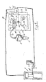
- FIG. 1 shows a storage container 3 in which a displacement side 18 is separated from a storage chamber 20 by a membrane 5.
- the chamber 20 opens with its outlet into an ejection nozzle 1.
- a valve (not shown here) can be provided between the chamber 20 and the ejection nozzle 1.
- the displacement side 18 of the storage container 3 is connected to the chamber 22 of a fluid cylinder 19 via a flexible line 15. Chamber 22 and a further chamber 23 are separated by a piston 17.
- Piston 17 is connected to a double piston rod, one piston rod 21 of which interacts, for example, with two limit switches 26 and 27. Limit switches 26 and 27 can represent limit positions for the displacement quantity, for example.
- the chamber 23 is connected to a fluid pump 25 via a line 34 in which a quantity control valve 24 is arranged. The system is protected against overpressure by the pressure relief valve 33.
- the functional sequence of the individual devices is coordinated, ensured and processed via a control 28.
- the limit switches 26 and 27 are connected to the control 28 by means of the lines 30 and 31.
- the quantity control valve 24 or its actuating device is connected to the control 28 via the line 32. This enables the correct dosing speed to be maintained and the limit positions determined in each case to be determined. This can mean that when the limit switch 26 is driven on - this information is passed on to the control 28 via the line 30 - the fluid pump 25 is switched off via the control line 33.
- the manipulator 11 or the transport device 11 can then be given the command, for example, via the control line 35, for example to drive the storage container 3 to the filling connection 9 and there to connect the ejection nozzle 1 to the filling connection 9 in order to carry out a filling.
- the barrel pump can be activated via line 29.
- the filling valve 12 is opened via the line 36.
- the barrel pump then drives the medium to be sprayed out through the ejection nozzle 1 into the storage chamber 20 and thus drives the hydraulic oil on the displacement side 18 back via the flexible line 15 back into the chamber 22 of the fluid cylinder 19, whereby the piston 17 is driven to the right again and the piston rod 21 is extended.
- the oil displaced from the chamber 23 can either be fed into the tank without pressure via a separate circuit, not shown, or through a bypass usually present in the flow control valve 24, or also through the flow control valve 24 itself and via the pressure relief valve 33 to the tank be.
- the pressure relief valve 33 could also be automatically adjustable so that the pressure relief is set very low for the return stroke.
- Such circuits are known per se and are not the subject of the invention.
- the displacement device 7, consisting essentially of the fluid cylinder 19 with the associated actuation devices, such as the fluid pump 25 and the pressure limiting valve 33 and the quantity control valve 24, is combined as an assembly and can be arranged on a stand 37, as shown in FIG. 2.
- the transport device 11 can be arranged in the form of a one-armed manipulator, for example.
- the supply station 8 is arranged with the storage barrel and the associated barrel pump, which is connected to the filling connection 9 by means of the line 38 via the filling valve 12.
- the control cabinet shown in Figure 2 may include the controller 28, but also in addition z. B. still a computer and programming devices for path programming of the manipulator 11th
- Figures 3 and 4 show only a simple modification of a device according to Figures 1 and 2.
- the embodiment of Figure 3 corresponds in its structure to the embodiment of Figure 1, but is essentially duplicated. Instead of the double arrangement, a multiple arrangement can also be provided. It is possible to feed the individual filling stations from the same supply station. However, it is also possible to provide several supply stations or to assign a separate supply station to each individual filling station. The supply stations can contain different media to be sprayed out. The respective storage containers must be assigned exactly to the individual filling stations for different media.
- the filling connections 9 and 10 are then assigned to the corresponding storage containers 3 and 4. In this case, the storage container 3 then has the separation 5 and the storage container 4 has the separation 6, each in the exemplary embodiment as Membrane formed on. It is also conceivable that the reservoirs 3 and 4 each differ in their structure from one another in adaptation to the media to be sprayed out.
- the entire device 13 contains two storage containers 3 and 4, which are connected to a displacement device 7 via the flexible lines 15 and 16, respectively.
- a displacement device 7 For the sake of simplicity, only one displacement device 7 is shown here. However, it is necessary to assign such a displacement device to each storage container.
- the storage container is just being picked up and filled by the filling connection 10 via its ejection nozzle 3, while the storage container 3 is moved in the intended manner by the manipulator 11 and the medium to be sprayed out is metered out by the displacement device 7. During this time, the storage container 4 can be filled. If the storage container 3 is emptied, it can be moved via the manipulator 11 to a free filling connection 9 or 10 and set down there. The storage container 4, which has meanwhile been filled, can then be removed immediately and the work operation continued with it.
Landscapes
- Physics & Mathematics (AREA)
- Fluid Mechanics (AREA)
- General Physics & Mathematics (AREA)
- Engineering & Computer Science (AREA)
- Mechanical Engineering (AREA)
- Robotics (AREA)
- Basic Packing Technique (AREA)
- Spray Control Apparatus (AREA)
Abstract
Description
- Die Erfindung betrifft eine Einrichtung zum dosierten Ausspritzen viskoser Medien mit mindestens einer Ausspritzdüse und einem Vorratsbehälter mit einer inneren Trennung zwischen Vorrats- und Verdrängungsseite, der mit einer Verdrängungseinrichtung verbunden ist, wobei die Verdrängungsmenge pro Zeit oder Weg mittels der Verdrängungseinrichtung bestimmbar ist.
- Einrichtungen der oben beschriebenen Art sind vom Anmelder selbst gebaut und in Verkehr gebracht worden. Sie werden eingesetzt beispielsweise zur Aufbringung streifenförmiger Beschichtungen an Bauteilen, wie z. B. zum Aufbringen des Dichtrandes an Kraftfahrzeugwindschutzscheiben. Solche Einrichtungen haben sich für den genannten Zweck in der Praxis durchaus gut bewährt. Es wird bei diesen Einrichtungen von einem einarmigen, ortsfesten Manipulator eine Ausspritzdüse entlang einer vorgegebenen Bahn verfahren und hierbei gleichzeitig aus der Ausspritzdüse das in aller Regel hochviskose Material ausgespritzt. Da das auszuspritzende Material sehr genau dosiert werden muß und hierbei die Geschwindigkeit der Ausspritzdüse entlang der vorgegebenen Bahn beachtet werden muß, ist der Einsatz einer kontrollierbaren Dosiereinrichtung notwendig. Diese Dosiereinrichtung besteht im Stand der Technik aus einem zylinderförmigen Behälter mit einem darin angeordneten, verschiebbaren Kolben. Dieser zylinderförmige Behälter wird aus einem Vorratsfaß, welches das auszuspritzende Medium enthält, über eine Leitung mittels einer Faßpumpe gefüllt, wobei der genannte Kolben ausgetrieben wird. Der genannte Zylinderraum ist ebenfalls - hierzu sind entsprechende Wegeventile vorgesehen - über eine großzügig bemessene, flexible Schlauchleitung mit der Ausspritzdüse verbunden. Ist der Zylinder über die entsprechende Wegeventilschaltung auf die Ausspritzdüse geschaltet, so kann über eine von einem Elektromotor bewegte Gewindespindel der Kolben wieder in den Zylinder eingedrückt und hierdurch das dort vorhandene Medium über die genannte flexible Schlauchleitung zur Ausspritzdüse transportiert und dort ausgespritzt werden. Über die Geschwindigkeit der Gewindespindel ist die auszuspritzende Menge dosierbar. Hierbei ist die Geschwindigkeit der Gewindespindel problemlos und präzise regelbar. Dennoch bleibt bei den Einrichtungen des Standes der Technik die präzise Dosierung insbesondere bei Geschwindigkeitsänderungen, beispielsweise dann, wenn die Ausspritzdüse von der geraden in eine kurvenförmige Bahn wechselt, schwierig, weil sich herausgestellt hat, daß Geschwindigkeitsänderungen an der die Auspressung bewirkenden Gewindespindel oder Geschwindigkeitsänderungen äquivalenter Elemente sich nur verzögert in einer Veränderung der ausgespritzten Masse pro Zeit auswirken. Die Größe dieser Verzögerung muß daher festgestellt werden für jeden einzelnen, vorbestimmten, von der Ausspritzdüse abzufahrenden Wegtypzyklus. Hierbei ist die genannte Verzögerung zusätzlich abhängig von der Viskosität des auszuspritzenden Mediums. Die notwendigerweise sehr groß bemessene flexible Leitung zwischen Verdrängungseinrichtung und Ausspritzdüse ist zudem hinderlich bei der Führung der Ausspritzdüse.
- Der Erfindung liegt damit die Aufgabe zugrunde, eine Einrichtung der eingangs beschriebenen Art vorzuschlagen, die in ihrem Aufbau einfacher gehalten werden kann und die gleichzeitig die beschriebenen Dosierunsicherheiten nicht mehr aufweist.
- Diese Aufgabe ist erfindungsgemäß gelöst durch mindestens einen bewegbaren Vorratsbehälter mit je einer Ausspritzdüse, durch mindestens einen mit einer Versorgungsstation verbundenen oder verbindbaren Füllanschluß, welch jeder mit einem von einer Transporteinrichtung auch zusammen mit der Ausspritzdüse bewegbaren Vorratsbehälter lösbar verbunden werden kann. Der jeweilige Vorratsbehälter mit Ausspritzdüse bildet eine Baueinheit, die klein und einfach zu handhaben ist. Die große, flexible und elastische Schlauchverbindung zwischen Verdrängungseinrichtung und Vorratsbehälter, in der das auszuspritzende Medium von der Verdrängungseinrichtung zum Vorratsbehälter transportiert wurde, ist entfallen. Auszuspritzendes Medium im Vorratsbehälter und Ausspritzdüse sind nunmehr unmittelbar benachbart. Es kann der jeweilige Vorratsbehälter leergespritzt und dann zu einer Füllstation zum erneuten Auffüllen transportiert werden. Der Aufbau der Einrichtung hat sich damit stark vereinfacht und es ist vor allen Dingen die bisherige Dosierunsicherheit beseitigt.
- Nach einer Ausgestaltung der Erfindung ist vorgeschlagen, daß zwischen Füllanschluß und Versorgungsstation mindestens ein Füllventil vorgesehen ist. Hierdurch ist eine saubere Trennung von Beginn und Ende des Füllvorgangs möglich und es kann außerdem bei mehreren Füllstationen auf die jeweils zu bedienende Station geschaltet werden.
- Eine andere Ausgestaltung der Erfindung sieht mindestens eine Transporteinrichtung vor, mit welcher mindestens ein Vorratsbehälter so positionierbar ist, daß er über den Füllanschluß gefüllt werden kann. Bei dieser Anordnung kann die Transporteinrichtung, die den Vorratsbehälter mit der Ausspritzdüse bewegt, auch dazu benutzt werden, den Vorratsbehälter zur Füllstation zu bringen und mit dem Füllanschluß so zu verbinden, daß eine Füllung erfolgen kann. Es ist jedoch insbesondere dann, wenn der Vorratsbehälter mit Spritzdüse stationär angeordnet sein sollte, ebenso umgekehrt möglich, den jeweiligen Füllanschluß über eine flexible Leitung mit der Versorgungsstation zu verbinden und dann den Füllanschluß zur Ausspritzdüse mit dem Vorratsbehälter zu bringen und dort die notwendige Füllverbindung herzustellen. Das bedeutet, daß die Transporteinrichtung nicht zwingend den Vorratsbehälter positionieren muß, sondern daß eine vorhandene Transporteinrichtung durchaus auch zusätzlich oder allein die Füllanschlüsse in die richtige Füllposition verfahren kann.
- Ergänzend ist nach der Erfindung vorgeschlagen, daß als Vorratsbehälter ein handelsüblicher Druckspeicher verwendet wird. Solche Einrichtungen haben sich in der Massenanwendung bewehrt, sind trotz hoher Druckfestigkeit leicht und handlich. Sie sind preiswert und als Ersatzteil jederzeit aus dem Lager des Herstellers zu beziehen.
- In weiterer Ausgestaltung der Erfindung sind mindestens zwei mit einer Versorgungsstation verbundene oder verbindbare Füllanschlüsse vorgesehen sowie mindestens eine Transporteinrichtung und mindestens zwei Vorratsbehälter zur Füllung mindestens eines Vorratsbehälters, während ein anderer Vorratsbehälter gleichzeitig entleert werden kann. Hierdurch steht im Wechsel immer ein gefüllter Vorratsbehälter zur Verfügung. Hierbei ist auch denkbar, daß die Vorratsbehälter jeweils unterschiedliche Medien enthalten, also mit unterschiedlichen Medien gefüllt werden. Dies bedeutet natürlich, daß auch Versorgungsstationen mit unterschiedlichen Medien vorhanden sein müssen.
- Weiterhin ist nach der Erfindung vorgesehen, daß die Füllanschlüsse an einem von der Transporteinrichtung erreichbaren Ort in der Einrichtung vorgesehen sind. Die Transporteinrichtung muß dann nicht zusätzliche Eigenschaften zur Erreichung der Füllstationen aufweisen, sondern kann in ihren technischen Möglichkeiten beschränkt bleiben auf den für ihren eigentlichen Einsatz notwendigen Umfang. Es soll also vermieden werden, daß die Transporteinrichtung zusätzliche Merkmale aufweisen muß, ausschließlich um die Füllstationen zu erreichen.
- Ergänzend ist dann nach der Erfindung noch vorgeschlagen, daß jeder Vorratsbehälter über eine flexible Leitung mit der Verdrängungseinrichtung verbunden ist. Hierdurch kann die Verdrängungseinrichtung stationär angeordnet sein. Im Gegensatz zum Stand der Technik verdrängt jetzt die Verdrängungseinrichtung selbst nicht mehr direkt das auszuspritzende Medium, sondern nur noch indirekt. Die Verdrängungseinrichtung ist nämlich über die Trennung im Vorratsbehälter vom Vorratsraum des Vorratsbehälters getrennt. Die Verdrängungseinrichtung kann daher über die genannte flexible Leitung ein inkompressibles Medium, wie z. B. Hydrauliköl, verdrängen, so daß im Vorratsraum des Vorratsbehälters ein ebensogroßes Raumvolumen verdrängt wird wie in der Verdrängungseinrichtung. Das inkompressible Medium überträgt eine Verdrängung verzögerungsfrei von der Verdrängungseinrichtung zum Vorratsbehälter und dies in gleicher Volumengröße. Die flexible Leitung kann hierdurch dünn und beweglich gehalten werden, so daß eine nennenswerte Behinderung von dieser Leitung nicht mehr ausgeht. Hier ist für jeden einzelnen Vorratsbehälter vorzugsweise auch eine separate Verdrängungseinrichtung vorzusehen.
- Es ist dann ergänzend vorgeschlagen, daß die Verdrängungseinrichtung einen beweglichen, betätigbaren Verdrängungskörper aufweist, wobei der Raum zwischen Verdrängungskörper und Verdrängungsseite des Vorratsbehälters andererseits mit einem im wesentlichten inkompressiblen Medium gefüllt ist, wie das oben bereits erläutert wurde. Eine Verschiebung des Verdrängungskörpers wird über das inkompressible Medium verzögerungsfrei und in gleicher Volumengröße auf die Vorratskammer des Vorratsbehälters übertragen. Mit einer entsprechenden Betätigung des Verdrängungskörpers läßt sich daher sehr präsize und ohne Verzögerung das Ausspritzvolumen pro Zeiteinheit beeinflussen.In weiterer Ergänzung ist dann nach der Erfindung noch vorgeschlagen, daß das verdrängbare Volumen eines jeden Vorratsbehälters dem Bedarf für einen zugeordneten Arbeitszyklus entspricht. Hierdurch können die Vorratsbehälter so klein wie möglich und handlich gehalten werden. Nach jedem Durchgang werden sie neu gefüllt, und es ist hierdurch gewährleistet, daß für den notwendigen Arbeitszyklus immer ausreichend auszuspritzendes Medium zur Verfügung steht.
- Eine andere ergänzende Ausgestaltung der Erfindung sieht vor, daß die Verdrängungseinrichtung mindestens einen Strömungsmittelzylinder aufweist, mit mindestens einem beweglichen Kolben als Verdrängungskörper. Dies ist eine konstruktiv einfach zu realisierende Möglichkeit für eine gut funktionsfähige und einfach zu regelnde Verdrängungseinrichtung. Die notwendigen Bauelemente können zudem Serienbauteile sein, die als solche somit bewährt und wenig störanfällig sind und als Ersatzteile jederzeit aus dem Vorratslager eines Herstellers erreichbar sind.
- Es ist dann weiter vorgesehen, daß der Strömungsmittelzylinder mindestens eine mit dem Kolben verbundene Kolbenstange aufweist, zur Abtastung des Verdrängungsweges des Kolbens und/oder zur Verbindung mit einem Verschiebemotor. Hierdurch kann das Verdrängungsvolumen und/oder eine Verdrängungsgrenzlage leicht erfaßt werden. Die Kolbenstange kann hierbei auch z. B. zusätzlich zur Verbindung beispielsweise mit einer von einem Elektromotor angetriebenen Kugelrollspindel verwendet werden, mit der Dosierweg und Dosiergeschwindigkeit bestimmt werden sollen.
- In weiterer Ausgestaltung der Erfindung ist vorgeschlagen, daß der der Verdrängerseite abgewandte Zylinderraum über ein Mengenregelventil mit einer Strömungsmittelpumpe verbunden ist. Dies ist eine alternative Form den Verdrängungsantrieb zu bewirken, die ebenfalls einfach im Aufbau und leicht beherrschbar ist.
- Wiederum eine Ausgestaltung der Erfindung sieh vor, daß jeder Vorratsbehälter als handelsüblicher Druckspeicher mit zwei Kammern ausgebildet ist, dessen eine Kammer die Verdrängungsseite und dessen andere Kammer die Vorratsseite bildet. Es hat sich gezeigt, daß handelsübliche Druckspeicher sich als Vorratsbehälter für den hier vorgesehenen Zweck ausgezeichnet eignen. Sie weisen von Ihrer Bauart her bereits eine innere flexible Membran auf, und enthalten damit bereits die notwendige Trennung zwischen Vorratsseite und Verdrängungsseite. Da solche Druckspeicher auch für Hydraulikflüssigkeiten ausgelegt sind, ist der Einsatz von Hydrauliköl auf der Verdrängerseite völlig unproblematisch. Sie weisen außerdem trotz ihrer in der Regel sehr leichten Bauart die notwendige Druckfestigkeit auf und sind sehr preiswert.
- Schließlich ist nach der Erfindung noch vorgesehen, daß als Transporteinrichtung ein stationärer Manipulator verwendet wird. Solche Manipulatoren, zum Teil auch mit der Bezeichnung "Roboter" belegt, sind vielfach in der Industrie bereits im Einsatz. Sie weisen die notwendige Bewegungsfähigkeit und die hier notwendige Tragfähigkeit auf. Lediglich ihre Greiforgane müssen an den zu greifenden Vorratsbehälter angepaßt sein
- Die Erfindung soll nun anhand der beigefügten Zeichnungen, die ein Ausführungsbeispiel zeigen, näher erläutert werden.
- Es zeigen:
- Figur 1: Schemaskizze des Aufbaus der neuerungsgemäßen Einrichtung
- Figur 2: Perspektivische Darstellung der Gesamteinrichtung nach Figur 1
- Figur 3: Einrichtung wie Figur 1, jedoch mit doppeltem Vorratsbehälter
- Figur 4: Perspektivisch Darstellung der gesamten Einrichtung nach Figur 3.
- Figur 1 zeigt einen Vorratsbehälter 3, bei dem eine Verdrängungsseite 18 von einer Vorratskammer 20 durch eine Membran 5 getrennt ist. Die Kammer 20 mündet mit ihrem Ausgang in eine Ausspritzdüse 1. Es kann bei Bedarf zwischen der Kammer 20 und der Ausspritzdüse 1 noch ein hier nicht dargestelltes Ventil vorgesehen sein.
- Die Verdrängungsseite 18 des Vorratsbehälters 3 ist über eine flexible Leitung 15 mit der Kammer 22 eines Strömungsmittelzylinders 19 verbunden. Kammer 22 und eine weitere Kammer 23 sind getrennt durch einen Kolben 17. Kolben 17 ist verbunden mit einer doppelten Kolbenstange, dessen eine Kolbenstange 21 beispielsweise zusammenwirkt mit zwei Endschaltern 26 and 27. Die Endschalter 26 und 27 können beispielsweise Grenzlagen für die Verdrängungsmenge darstellen. Zur Betätigung des Kolbens 17 ist die Kammer 23 über eine Leitung 34, in der ein Megenregelventil 24 angeordnet ist, mit einer Strömungsmittelpumpe 25 verbunden. Das System ist gegen Überdruck abgesichert durch das Druckbegrenzungsventil 33.
- Der Funktionsablauf der einzelnen Einrichtungen wird über eine Steuerung 28 koordiniert, sichergestellt und abgewickelt. Die Endschalter 26 und 27 sind hierzu mittels der Leitungen 30 und 31 mit der Steuerung 28 verbunden. Ebenso ist das Mengenregelventil 24 bzw. dessen Stelleinrichtung über die Leitung 32 mit der Steuerung 28 verbunden. Hierdurch kann die richtige Dosiergeschwindigkeit eingehalten und die jeweils festgelegten Grenzlagen ermittelt werden. So kann dies bedeuten, daß bei Befahren des Endschalters 26 - diese Information wird über die Leitung 30 an die Steuerung 28 gegeben - die Strömungsmittelpumpe 25 über die Steuerleitung 33 abgeschaltet wird. Es kann dann beispielsweise über die Steuerleitung 35 der Manipulator 11 oder die Transporteinrichtung 11 das Kommando bekommen, beispielsweise den Vorratsbehälter 3 zum Füllanschluß 9 zu fahren und dort die Ausspritzdüse 1 mit dem Füllanschluß 9 zur Durchführung einer Füllung zu verbinden. Ist diese Verbindung hergestellt, so kann die Faßpumpe über die Leitung 29 aktiviert werden. Über die Leitung 36 wird das Füllventil 12 geöffnet. Die Faßpumpe treibt dann das auszuspritzende Medium durch die Ausspritzdüse 1 in die Vorratskammer 20 und treibt damit auf der Verdrängungsseite 18 das Hydrauliköl über die flexible Leitung 15 wieder zurück in die Kammer 22 des Strömungsmittelzylinders 19, wodurch der Kolben 17 wieder nach rechts getrieben und die Kolbenstange 21 ausgefahren wird. Das aus der Kammer 23 verdrängte Öl kann entweder über eine nicht dargestellte separate Schaltung drucklos in den Tank geführt werden, oder aber durch eine in dem Mengenregelventil 24 üblicherweise vorhandene Umgehung, oder auch durch das Mengenregelventil 24 selbst zurück und über das Druckbegrenzungsventil 33 zum Tank geführt sein. Hierzu könnte das Druckbegrenzungsventil 33 auch automatisch so regelbar sein, daß für den Rückhub die Druckbegrenzung sehr niedrig gestellt wird. Solche Schaltungen aber sind ansich bekannt und nicht Gegenstand der Erfindung.
Wird nun der Endschalter 27 befahren, so kann die Steuerung 28 über die Leitung 29 die Fülleinrichtung wieder abschalten und über die Leitung 36 das Füllventil 12 wieder schließen. Die Transporteinrichtung 11 erhält nun eine Information darüber, daß der Vorratsbehälter 3 wieder gefüllt und abholbereit am Füllanschluß zur Verfügung steht. Hat die Transporteinrichtung den Vorratsbehälter 3 wieder übernommen bzw. in die Anfangsposition gefahren, so kann die Steuerung 28 über die Leitung 33 die Strömungsmittelpumpe 25 wieder einschalten und eine bedarfsgerechte Mengenregelung am Mengenregelventil 24 bewirken. - Die im wesentlichen aus dem Strömungsmittelzylinder 19 mit den zugehörigen Betätigungseinrichtungen, wie der Strömungsmittelpumpe 25 und dem Druckbegrenzungsventil 33 sowie dem Mengenregelventil 24 bestehende Verdrängungseinrichtung 7 ist als Baugruppe zusammengefaßt und kann an einem Ständer 37, wie dies Figur 2 zeigt, angeordnet sein. Am gleichen Ständer kann in einer Anordnung wie in Figur 2 dargestellt, die Transporteinrichtung 11 in der Form beispielsweise eines einarmigen Manipulators angeordnet sein. Neben dem Ständer 37 ist die Versorgungsstation 8 mit dem Vorratsfaß und der zugehörigen Faßpumpe angeordnet, die mittels der Leitung 38 über das Füllventil 12 mit dem Füllanschluß 9 verbunden ist. Der in Figur 2 noch dargestellte Schaltschrank kann die Steuerung 28 umfassen, aber auch zusätzlich z. B. noch einen Rechner und Programiereinrichtungen für eine Wegprogramierung des Manipulators 11.
- Die Figuren 3 und 4 zeigen lediglich eine einfache Modifizierung einer Einrichtung nach den Figuren 1 und 2. Die Ausführungsform nach Figur 3 entspricht in ihrem Aufbau der Ausführungsform nach Figur 1, ist jedoch im wesentlichen doppelt vorhanden. Statt der doppelten Anordnung kann auch eine Mehrfachanordnung vorgesehen sein. Hierbei ist es möglich, die einzelnen Füllstationen aus der gleichen Versorgungsstation zu speisen. Es ist aber auch möglich, mehrere Versorgungsstationen vorzusehen oder auch jeder einzelnen Füllstation eine separate Versorgungsstation zuzuordnen. Hierbei können die Versorgungsstationen durchaus unterschiedliche auszuspritzende Medien enthalten. Die jeweiligen Vorratsbehälter müssen bei unterschiedlichen Medien den einzelnen Füllstationen exakt zugeordnet sein. Die Füllanschlüsse 9 und 10 sind dann den entsprechenden Vorratsbehältern 3 und 4 zugeordnet. Hierbei weist dann der Vorratsbehälter 3 die Trennung 5 und der Vorratsbehälter 4 die Trennung 6, im Ausführungsbeispiel jeweils als Membran ausgebildet, auf. Es ist auch denkbar, daß sich die Vorratsbehälter 3 und 4 jeweils in ihrem Aufbau voneinander unterscheiden in Anpassung an die auszuspritzenden Medien.
- Bei eine Ausführungsform nach Figur 3 enthält die Gesamteinrichtung 13 zwei Vorratsbehälter 3 und 4, die über die flexiblen Leitungen 15 bzw. 16 mit einer Verdrängungseinrichtung 7 verbunden sind. Der Einfachheit halber ist hier nur eine Verdrängungseinrichtung 7 gezeichnet. Es ist jedoch notwendig, jedem Vorratsbehälter jeweils eine solche Verdrängungseinrichtung zuzuordnen.
- Im Ausführungsbeispiel nach den Figuren 3 und 4 wird der Vorratsbehälter über seine Ausspritzdüse 3 gerade vom Füllanschluß 10 aufgenommen und gefüllt, während der Vorratsbehälter 3 vom Manipulator 11 in vorgesehener Weise verfahren wird und dabei das auszuspritzende Medium, dosiert von der Verdrängungseinrichtung 7, ausspritzt. In dieser Zeit kann derVorratsbehälter 4 gefüllt werden. Ist der Vorratsbehälter 3 entleert, so kann er über den Manipulator 11 zu einem freien Füllanschluß 9 oder 10 gefahren und dort abgesetzt werden. Der inzwischen gefüllte Vorratsbehälter 4 kann danach sofort entnommen und mit diesem der Arbeitsvorgang fortgesetzt werden.
- Es ist insgesamt gelungen einen sehr einfachen Aufbau einer solchen Einrichtung zu erreichen und gleichzeitig die bisherigen Dosierschwierigkeiten zu beseitigen.
-
- 1 Ausspritzdüse
- 2 Ausspritzdüse
- 3 Vorratsbehälter
- 4 Vorratsbehälter
- 5 Trennung
- 6 Trennung
- 7 Verdrängungseinrichtung
- 8 Versorgungsstation
- 9 Füllanschluß
- 10 Füllanschluß
- 11 Transporteinrichtung
- 12 Füllventil
- 13 Einrichtung
- 14 Einrichtung
- 15 flexible Leitung
- 16 flexible Leitung
- 17 Verdrängungskörper
- 18 Verdrängungsseite
- 19 Strömungsmittelzylinder
- 20 Kammer
- 21 Kolbenstange
- 22 Zylinderraum
- 23 Zylinderraum
- 24 Mengenregelventil
- 25 Strömungsmittelpumpe
- 26 Endschalter
- 27 Endschalter
- 28 Steuerung
- 29 Leitung
- 30 Leitung
- 31 Leitung
- 32 Leitung
- 33 Druckbegrenzungsventil
- 34 Leitung
- 35 Leitung
- 36 Leitung
- 37 Ständer
- 38 Leitung
Claims (14)
Applications Claiming Priority (2)
| Application Number | Priority Date | Filing Date | Title |
|---|---|---|---|
| DE8633671U DE8633671U1 (de) | 1986-12-17 | 1986-12-17 | Einrichtung zum dosierten Ausspritzen viskoser Medien |
| DE8633671U | 1986-12-17 |
Publications (3)
| Publication Number | Publication Date |
|---|---|
| EP0271640A2 true EP0271640A2 (de) | 1988-06-22 |
| EP0271640A3 EP0271640A3 (en) | 1989-08-09 |
| EP0271640B1 EP0271640B1 (de) | 1991-04-17 |
Family
ID=6801202
Family Applications (1)
| Application Number | Title | Priority Date | Filing Date |
|---|---|---|---|
| EP87112610A Expired - Lifetime EP0271640B1 (de) | 1986-12-17 | 1987-08-29 | Einrichtung zum dosierten Ausspritzen viskoser Medien |
Country Status (3)
| Country | Link |
|---|---|
| EP (1) | EP0271640B1 (de) |
| DE (2) | DE8633671U1 (de) |
| ES (1) | ES2022237B3 (de) |
Cited By (3)
| Publication number | Priority date | Publication date | Assignee | Title |
|---|---|---|---|---|
| DE4220048A1 (de) * | 1992-06-19 | 1993-12-23 | Fft Flexible Fertigungstechnik | Regel- und steuerbares Auftragssystem für viskose Medien |
| US7059844B2 (en) | 1993-06-14 | 2006-06-13 | EMI—TEC Elektronische Materialien GmbH | Process for producing a casing providing a screen against electromagnetic radiation |
| DE10004089B4 (de) * | 2000-01-31 | 2007-05-03 | Centre Luxembourgeois de Recherches pour le Verre et la Céramique S.A., Dudelange | Gebäudefenster mit extrudierter Dichtung |
Families Citing this family (6)
| Publication number | Priority date | Publication date | Assignee | Title |
|---|---|---|---|---|
| IT1203874B (it) * | 1987-04-09 | 1989-02-23 | Bayer Italia Spa | Metodo e dispositivo per la produzione di una parte stampata a partire da una massa da stampaggio duroplastica contenente fibre |
| FR2632891B1 (fr) * | 1988-06-17 | 1990-10-19 | Saint Gobain Vitrage | Amelioration a la fabrication d'un cordon de matiere organique destine a servir de joint et d'intercalaire dans un vitrage multiple |
| FR2666272B1 (fr) * | 1990-08-30 | 1994-06-03 | Alsthom Gec | Dispositif pour la coulee de materiaux thermodurcissables. |
| DE4208884C2 (de) * | 1991-03-27 | 1997-03-20 | Sca Schucker Gmbh | Verfahren und Vorrichtung zum Aufbringen einer aus einem härtbaren Klebstoff bestehenden pastösen Masse |
| DE9312276U1 (de) * | 1993-08-17 | 1993-12-02 | Schneider, Friedhelm, 51580 Reichshof | Dosiergerät für Membrankolben für hochviskose Flüssigkeit |
| FR2768958B1 (fr) * | 1997-09-30 | 1999-12-24 | Ecia Equip Composants Ind Auto | Installation de fabrication de pieces en matiere thermoplastique notamment pour vehicules automobiles |
Family Cites Families (2)
| Publication number | Priority date | Publication date | Assignee | Title |
|---|---|---|---|---|
| FR2411797A1 (fr) * | 1977-12-16 | 1979-07-13 | Gruffy Georges | Dispositif de stockage et de tirage de biere pression par container souple |
| US4594057A (en) * | 1985-06-10 | 1986-06-10 | Morgan Products, Inc. | Injector pump |
-
1986
- 1986-12-17 DE DE8633671U patent/DE8633671U1/de not_active Expired
-
1987
- 1987-08-29 DE DE8787112610T patent/DE3769447D1/de not_active Expired - Fee Related
- 1987-08-29 EP EP87112610A patent/EP0271640B1/de not_active Expired - Lifetime
- 1987-08-29 ES ES87112610T patent/ES2022237B3/es not_active Expired - Lifetime
Cited By (3)
| Publication number | Priority date | Publication date | Assignee | Title |
|---|---|---|---|---|
| DE4220048A1 (de) * | 1992-06-19 | 1993-12-23 | Fft Flexible Fertigungstechnik | Regel- und steuerbares Auftragssystem für viskose Medien |
| US7059844B2 (en) | 1993-06-14 | 2006-06-13 | EMI—TEC Elektronische Materialien GmbH | Process for producing a casing providing a screen against electromagnetic radiation |
| DE10004089B4 (de) * | 2000-01-31 | 2007-05-03 | Centre Luxembourgeois de Recherches pour le Verre et la Céramique S.A., Dudelange | Gebäudefenster mit extrudierter Dichtung |
Also Published As
| Publication number | Publication date |
|---|---|
| EP0271640B1 (de) | 1991-04-17 |
| DE3769447D1 (de) | 1991-05-23 |
| EP0271640A3 (en) | 1989-08-09 |
| DE8633671U1 (de) | 1988-01-07 |
| ES2022237B3 (es) | 1991-12-01 |
Similar Documents
| Publication | Publication Date | Title |
|---|---|---|
| EP0132457B1 (de) | Teilesatz für Mehrkomponentenerzeugnisse | |
| DE69116670T2 (de) | Verfahren und Vorrichtung zur Durchflussregelung | |
| DE2809846C2 (de) | ||
| EP1213529B1 (de) | Schmierstoffspender | |
| DE3725172A1 (de) | Verfahren und anlage zum elektrostatischen beschichten mit leitfaehigem material | |
| EP0271662B1 (de) | Einrichtung zum Dosierten Ausspritzen viskoser Medien | |
| EP0271640B1 (de) | Einrichtung zum dosierten Ausspritzen viskoser Medien | |
| DE10115463A1 (de) | Zerstäuber für eine Beschichtungsanlage und Verfahren zu seiner Materialversorgung | |
| DE2742804A1 (de) | Abgabevorrichtung fuer schmelzkleber | |
| EP0245790B1 (de) | Vorrichtung zum Dosieren von Reaktionsgemischen | |
| DE4400943A1 (de) | Vorrichtung zum Anordnen, Füllen und Verschweißen von Hülsen für die künstliche Besamung | |
| DE2415237A1 (de) | Vorrichtung zum dosierten abfuellen von fluessigen, im ruhezustand erstarrenden stoffen, wie margarine o.dgl. | |
| DE1801555C3 (de) | Einspritzvorrichtung für Wachs oder ähnliche plastische Massen | |
| DE1917157A1 (de) | Einrichtung zum Auftragen von Proben auf chromatographische Saeulen | |
| DE19704573A1 (de) | Vorrichtung und Verfahren zur Lackierung von Kraftfahrzeugkarossen | |
| DE1598223B2 (de) | Einrichtung zum selbsttaetigen auftragen von proben auf chromatographische kolonnen | |
| DE1779280B2 (de) | Verfahren zum einspritzen von kunststoffmaterial aus einem ersten und einem zweiten einspritzzylinder in eine spritzgiessform | |
| EP0771268B1 (de) | Sprühfeuchtwerk | |
| DE2101351C3 (de) | Vorrichtung zum portionierten Abfüllen von zähflüssigem, insbesondere hochviskosem Füllgut | |
| EP1010469A2 (de) | Verfahren und System zur Farbversorgung einer elektrostatischen Beschichtungsanlage | |
| DE2008103A1 (de) | Verfahren und Vorrichtung zum Ver schließen einer Filmkassette aus Kunst | |
| DE3831785A1 (de) | Verfahren und vorrichtung zum nachfuellen einer hochviskosen, pastoesen substanz in einen speicher einer vorrichtung zum auftragen dieser substanz auf werkstuecke | |
| DE4310019C1 (de) | Druckelastischer Flüssigkeitsbehälter aus Kunststoff mit Dosierkammer | |
| DE1491721B1 (de) | Injektionsspritze | |
| WO1995005538A1 (de) | Anordnung zum öffnen und schliessen einer verschlusskappe |
Legal Events
| Date | Code | Title | Description |
|---|---|---|---|
| PUAI | Public reference made under article 153(3) epc to a published international application that has entered the european phase |
Free format text: ORIGINAL CODE: 0009012 |
|
| AK | Designated contracting states |
Kind code of ref document: A2 Designated state(s): BE DE ES FR GB IT NL SE |
|
| PUAL | Search report despatched |
Free format text: ORIGINAL CODE: 0009013 |
|
| RAP1 | Party data changed (applicant data changed or rights of an application transferred) |
Owner name: VEGLA VEREINIGTE GLASWERKE GMBH |
|
| AK | Designated contracting states |
Kind code of ref document: A3 Designated state(s): BE DE ES FR GB IT NL SE |
|
| 17P | Request for examination filed |
Effective date: 19891025 |
|
| 17Q | First examination report despatched |
Effective date: 19900921 |
|
| GRAA | (expected) grant |
Free format text: ORIGINAL CODE: 0009210 |
|
| AK | Designated contracting states |
Kind code of ref document: B1 Designated state(s): BE DE ES FR GB IT NL SE |
|
| PG25 | Lapsed in a contracting state [announced via postgrant information from national office to epo] |
Ref country code: NL Effective date: 19910417 |
|
| REF | Corresponds to: |
Ref document number: 3769447 Country of ref document: DE Date of ref document: 19910523 |
|
| GBT | Gb: translation of ep patent filed (gb section 77(6)(a)/1977) | ||
| ITF | It: translation for a ep patent filed | ||
| ET | Fr: translation filed | ||
| NLV1 | Nl: lapsed or annulled due to failure to fulfill the requirements of art. 29p and 29m of the patents act | ||
| PLBE | No opposition filed within time limit |
Free format text: ORIGINAL CODE: 0009261 |
|
| STAA | Information on the status of an ep patent application or granted ep patent |
Free format text: STATUS: NO OPPOSITION FILED WITHIN TIME LIMIT |
|
| 26N | No opposition filed | ||
| PGFP | Annual fee paid to national office [announced via postgrant information from national office to epo] |
Ref country code: FR Payment date: 19930706 Year of fee payment: 7 |
|
| PGFP | Annual fee paid to national office [announced via postgrant information from national office to epo] |
Ref country code: SE Payment date: 19930719 Year of fee payment: 7 |
|
| PGFP | Annual fee paid to national office [announced via postgrant information from national office to epo] |
Ref country code: ES Payment date: 19930813 Year of fee payment: 7 |
|
| PGFP | Annual fee paid to national office [announced via postgrant information from national office to epo] |
Ref country code: GB Payment date: 19930819 Year of fee payment: 7 |
|
| PG25 | Lapsed in a contracting state [announced via postgrant information from national office to epo] |
Ref country code: GB Effective date: 19940829 |
|
| PG25 | Lapsed in a contracting state [announced via postgrant information from national office to epo] |
Ref country code: SE Effective date: 19940830 Ref country code: ES Free format text: LAPSE BECAUSE OF NON-PAYMENT OF DUE FEES Effective date: 19940830 |
|
| EAL | Se: european patent in force in sweden |
Ref document number: 87112610.8 |
|
| GBPC | Gb: european patent ceased through non-payment of renewal fee |
Effective date: 19940829 |
|
| PG25 | Lapsed in a contracting state [announced via postgrant information from national office to epo] |
Ref country code: FR Effective date: 19950428 |
|
| EUG | Se: european patent has lapsed |
Ref document number: 87112610.8 |
|
| REG | Reference to a national code |
Ref country code: FR Ref legal event code: ST |
|
| PGFP | Annual fee paid to national office [announced via postgrant information from national office to epo] |
Ref country code: BE Payment date: 20010627 Year of fee payment: 15 |
|
| PGFP | Annual fee paid to national office [announced via postgrant information from national office to epo] |
Ref country code: DE Payment date: 20010913 Year of fee payment: 15 |
|
| PG25 | Lapsed in a contracting state [announced via postgrant information from national office to epo] |
Ref country code: BE Free format text: LAPSE BECAUSE OF NON-PAYMENT OF DUE FEES Effective date: 20020831 |
|
| BERE | Be: lapsed |
Owner name: *VEGLA VEREINIGTE GLASWERKE G.M.B.H. Effective date: 20020831 |
|
| PG25 | Lapsed in a contracting state [announced via postgrant information from national office to epo] |
Ref country code: DE Free format text: LAPSE BECAUSE OF NON-PAYMENT OF DUE FEES Effective date: 20030301 |
|
| REG | Reference to a national code |
Ref country code: ES Ref legal event code: FD2A Effective date: 19950911 |
|
| PG25 | Lapsed in a contracting state [announced via postgrant information from national office to epo] |
Ref country code: IT Free format text: LAPSE BECAUSE OF NON-PAYMENT OF DUE FEES;WARNING: LAPSES OF ITALIAN PATENTS WITH EFFECTIVE DATE BEFORE 2007 MAY HAVE OCCURRED AT ANY TIME BEFORE 2007. THE CORRECT EFFECTIVE DATE MAY BE DIFFERENT FROM THE ONE RECORDED. Effective date: 20050829 |