EP0271740A2 - Dispositif pour allumer ou éteindre un appareil monté dans un véhicule automobile - Google Patents
Dispositif pour allumer ou éteindre un appareil monté dans un véhicule automobile Download PDFInfo
- Publication number
- EP0271740A2 EP0271740A2 EP87117189A EP87117189A EP0271740A2 EP 0271740 A2 EP0271740 A2 EP 0271740A2 EP 87117189 A EP87117189 A EP 87117189A EP 87117189 A EP87117189 A EP 87117189A EP 0271740 A2 EP0271740 A2 EP 0271740A2
- Authority
- EP
- European Patent Office
- Prior art keywords
- switching
- ignition lock
- switching device
- ignition
- arrangement according
- Prior art date
- Legal status (The legal status is an assumption and is not a legal conclusion. Google has not performed a legal analysis and makes no representation as to the accuracy of the status listed.)
- Granted
Links
Images
Classifications
-
- B—PERFORMING OPERATIONS; TRANSPORTING
- B60—VEHICLES IN GENERAL
- B60R—VEHICLES, VEHICLE FITTINGS, OR VEHICLE PARTS, NOT OTHERWISE PROVIDED FOR
- B60R16/00—Electric or fluid circuits specially adapted for vehicles and not otherwise provided for; Arrangement of elements of electric or fluid circuits specially adapted for vehicles and not otherwise provided for
- B60R16/02—Electric or fluid circuits specially adapted for vehicles and not otherwise provided for; Arrangement of elements of electric or fluid circuits specially adapted for vehicles and not otherwise provided for electric constitutive elements
- B60R16/023—Electric or fluid circuits specially adapted for vehicles and not otherwise provided for; Arrangement of elements of electric or fluid circuits specially adapted for vehicles and not otherwise provided for electric constitutive elements for transmission of signals between vehicle parts or subsystems
Definitions
- the invention relates to an arrangement for switching on or off a device operated in a motor vehicle, in particular a car radio, consisting of a switching device which can be actuated with the ignition lock of the motor vehicle and a switching device arranged in the device itself.
- connection options for a car radio in a motor vehicle Either the device is connected to a constantly live line or it is connected to a line in which the power supply can be interrupted by the ignition lock of the motor vehicle.
- the first possibility has the disadvantage that the device must always be operated again at the start and end of the trip via the switch arranged in the device, it being very easy to forget to switch off when leaving the vehicle and the vehicle battery is thereby unnecessarily discharged.
- the ignition lock has a so-called “park” position, in which the power supply to the connected device is established without switching on the ignition.
- the ignition key is usually not removable in this position. For children left behind in the car who, for example, For example, hearing a cassette poses a significant risk. Even if the key could be removed, this could often be forgotten.
- the invention has for its object to provide an arrangement of the type specified in the preamble of claim 1 so that even when the "lock" position of the ignition lock is omitted, the device operated in the vehicle can be switched on and off via the ignition lock and secondly the ignition switch position "Off" can be operated.
- the switching device coupled to the ignition lock delivers a logic level corresponding to the respective position of the ignition lock at its output. Furthermore, a bistable flip-flop circuit is provided, which changes its switching state each time the switching device arranged in the device itself is actuated and also supplies a logic level corresponding to the respective switching state at its output.
- the digital signals supplied by the switching device of the ignition lock and by the bistable multivibrator are linked via a switching logic which generates the control signal necessary for switching the device on and off.
- the switching logic provided is advantageously designed such that the device to be operated can be switched on and off independently of the position of the ignition lock by means of the switching device arranged in the device itself.
- the power supply to the device is basically interrupted when the ignition lock is switched from the "on” to the "off” position (switching off the vehicle engine), while when the ignition lock is switched from the "off” to the “on” position the original operating state of the device is restored. For example, if the device was switched on before the vehicle engine was switched off, this operating state is restored when the engine is started again. Accordingly, both the switching position and the switching direction of the ignition lock, as well as the switching position of the bistable flip-flop circuit arranged in the device, are evaluated via the switching logic and, depending on this, the control signal necessary for switching the device on and off is generated.
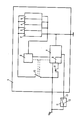
- the figure shows a device 1 to be operated in a motor vehicle, consisting of a receiving part 2, a cassette part 3, an LF part 4 and a lighting device 5.
- the device is on the one hand and on the other hand via an ignition lock 11 with the battery voltage U B connected.
- the ignition lock 11 has only two positions and is coupled to a switching device 12.
- the battery voltage U B leads via a switch 10, which can be controlled by a switching logic 7 and a timer circuit 6, to the device circuits 2 to 5 to be supplied.
- the switching logic includes a bistable multivibrator 8, e.g. B. a flip-flop, integrated, the switching state can be changed via a switching device 9, in such a way that the switching state of the flip-flop 8 changes each time the switching device 9 is actuated.
- the switching logic 7 determines the position of the ignition lock 11 via the output 13 of the switching device 12.
- the switching logic 7 is thus available to the switching logic 7 via the switching device 12 and the flip-flop 8 and, with a corresponding logical combination, controls the desired switching functions.
- the logical combination of the two digital signals can be done either by a suitable arrangement of gates or by program-controlled software using a microprocessor.
- the time circuit 6 provided in the exemplary embodiment advantageously leaves the device 1 in the switched-on state only for a predetermined time.
- the relevant time circuit is only activated when certain digital signals are linked, for example when the output 13 of the switching device 12 is at a "low level” and the switching position of the flip-flop 8 is activated by actuating the switching device 9 from “low”. goes to "high”.
- the ignition lock is in the "off” position and the device is switched on via the switching device 9.
- the switching device 9 is preferably designed as a non-latching tip button, which replaces the conventional current-operated operating voltage switch and z. B. can be arranged on the volume control of the device 1.
Landscapes
- Engineering & Computer Science (AREA)
- Mechanical Engineering (AREA)
- Lock And Its Accessories (AREA)
- Control Of Direct Current Motors (AREA)
- Stopping Of Electric Motors (AREA)
- Relay Circuits (AREA)
Priority Applications (1)
| Application Number | Priority Date | Filing Date | Title |
|---|---|---|---|
| AT87117189T ATE63728T1 (de) | 1986-12-17 | 1987-11-21 | Anordnung zum ein- bzw. ausschalten eines in einem kraftfahrzeug betriebenen geraetes. |
Applications Claiming Priority (2)
| Application Number | Priority Date | Filing Date | Title |
|---|---|---|---|
| DE3642996 | 1986-12-17 | ||
| DE19863642996 DE3642996A1 (de) | 1986-12-17 | 1986-12-17 | Anordnung zum ein- bzw. ausschalten eines in einem kraftfahrzeug betriebenen geraetes |
Publications (3)
| Publication Number | Publication Date |
|---|---|
| EP0271740A2 true EP0271740A2 (fr) | 1988-06-22 |
| EP0271740A3 EP0271740A3 (en) | 1989-04-05 |
| EP0271740B1 EP0271740B1 (fr) | 1991-05-22 |
Family
ID=6316334
Family Applications (1)
| Application Number | Title | Priority Date | Filing Date |
|---|---|---|---|
| EP87117189A Expired - Lifetime EP0271740B1 (fr) | 1986-12-17 | 1987-11-21 | Dispositif pour allumer ou éteindre un appareil monté dans un véhicule automobile |
Country Status (3)
| Country | Link |
|---|---|
| EP (1) | EP0271740B1 (fr) |
| AT (1) | ATE63728T1 (fr) |
| DE (2) | DE3642996A1 (fr) |
Cited By (3)
| Publication number | Priority date | Publication date | Assignee | Title |
|---|---|---|---|---|
| FR2634334A1 (fr) * | 1988-07-12 | 1990-01-19 | Radiotechnique Ind & Comm | Dispositif de commande logique de commutation de l'alimentation d'un autoradio |
| EP0444929A3 (en) * | 1990-03-01 | 1992-08-26 | Nec Corporation | Power source control system for automobile telephone |
| EP0814571A3 (fr) * | 1996-06-21 | 2003-03-12 | Robert Bosch Gmbh | Récepteur de radiodiffusion avec un dispositif téléphonique intégré |
Families Citing this family (4)
| Publication number | Priority date | Publication date | Assignee | Title |
|---|---|---|---|---|
| DE3914848A1 (de) * | 1989-05-05 | 1990-11-08 | Grundig Emv | Anordnung zur einschaltverzoegerung eines in einem kraftfahrzeug betriebenen geraetes |
| DE4041620C2 (de) * | 1990-12-22 | 2003-02-20 | Bosch Gmbh Robert | Einrichtung zur Spannungsversorgung bei Geräten mit Nachlauf |
| DE4241012A1 (de) * | 1992-12-05 | 1994-06-09 | Blaupunkt Werke Gmbh | Anordnung zum automatischen Abschalten eines in einem Kfz betriebenen Autoradio |
| RU2129497C1 (ru) * | 1998-07-24 | 1999-04-27 | Раев Михаил Наумович | Устройство для отключения системы освещения транспортного средства |
Family Cites Families (3)
| Publication number | Priority date | Publication date | Assignee | Title |
|---|---|---|---|---|
| US3646354A (en) * | 1970-11-05 | 1972-02-29 | Joe W Von Brimer | Electrical supervisory control |
| US3739187A (en) * | 1972-09-12 | 1973-06-12 | Amp Inc | Remote switching system |
| DE3304103C2 (de) * | 1983-02-08 | 1985-02-14 | Daimler-Benz Ag, 7000 Stuttgart | Vorrichtung zur Energieversorgung von Rundfunkgeräten in Kraftfahrzeugen |
-
1986
- 1986-12-17 DE DE19863642996 patent/DE3642996A1/de active Granted
-
1987
- 1987-11-21 EP EP87117189A patent/EP0271740B1/fr not_active Expired - Lifetime
- 1987-11-21 AT AT87117189T patent/ATE63728T1/de not_active IP Right Cessation
- 1987-11-21 DE DE8787117189T patent/DE3770249D1/de not_active Expired - Lifetime
Cited By (3)
| Publication number | Priority date | Publication date | Assignee | Title |
|---|---|---|---|---|
| FR2634334A1 (fr) * | 1988-07-12 | 1990-01-19 | Radiotechnique Ind & Comm | Dispositif de commande logique de commutation de l'alimentation d'un autoradio |
| EP0444929A3 (en) * | 1990-03-01 | 1992-08-26 | Nec Corporation | Power source control system for automobile telephone |
| EP0814571A3 (fr) * | 1996-06-21 | 2003-03-12 | Robert Bosch Gmbh | Récepteur de radiodiffusion avec un dispositif téléphonique intégré |
Also Published As
| Publication number | Publication date |
|---|---|
| ATE63728T1 (de) | 1991-06-15 |
| DE3642996C2 (fr) | 1990-03-08 |
| EP0271740B1 (fr) | 1991-05-22 |
| DE3770249D1 (de) | 1991-06-27 |
| EP0271740A3 (en) | 1989-04-05 |
| DE3642996A1 (de) | 1988-06-30 |
Similar Documents
| Publication | Publication Date | Title |
|---|---|---|
| DE2911998C2 (de) | Stromversorgung für einen Mikroprozessor, der elektrische Einrichtungen, insbesondere eines Kraftfahrzeuges steuert | |
| EP0486509B1 (fr) | Circuit d'activation pour un microprocesseur | |
| DE3505306C2 (fr) | ||
| DE19916966A1 (de) | Elektronische Zündstartschalter- und Lenkradverriegelungsvorrichtung | |
| DE60116223T2 (de) | Gerät und Methode, um einen Fahrzeugsmotor anzulassen | |
| DE2747733A1 (de) | Digitale elektronische steuerschaltung | |
| DE3609718A1 (de) | Zuendsystem fuer fahrzeuge | |
| EP0271740B1 (fr) | Dispositif pour allumer ou éteindre un appareil monté dans un véhicule automobile | |
| DE4015271A1 (de) | Schaltungsanordnung zur abfrage von schalterstellungen | |
| DE2618028C2 (de) | Universell einsetzbares, in integrierter Schaltkreistechnik ausführbares Zeitglied | |
| DE9404382U1 (de) | Möbelantrieb | |
| EP1001527A2 (fr) | Circuit générateur d'un signal de sortie | |
| DE10119212B4 (de) | Vorrichtung und Verfahren für einen Zündschalterstatus | |
| DE69112868T2 (de) | Ein-/Aus- Schaltung mit Verrieglungsfunktion. | |
| EP0687916A2 (fr) | Procédé pour tester un circuit intégré ainsi q'un circuit intégré avec circuit de test | |
| DE19963191B4 (de) | Vorrichtung und Verfahren für die Beleuchtung, insbesondere die Innenraumbeleuchtung eines Kraftfahrzeuges | |
| DE69607540T2 (de) | Diebstahlschutzsystem für ein Kraftfahrzeug | |
| DE69508673T2 (de) | Elektrischer Stromsteuerungskreis für Schalter | |
| EP2624275A1 (fr) | Commutateur électrique | |
| DE2918501C2 (fr) | ||
| DE3914848C2 (fr) | ||
| DE69421075T2 (de) | Überlastschutzanordnung für eine integrierte Schaltung und entsprechendes Verfahren | |
| DE602004008498T2 (de) | Mehrfachsteuervorrichtung für elektrische motoren | |
| DE1580760C3 (de) | Elektrische Schalteinrichtung fur einen Scheibenwischermotor in Kraftfahrzeugen | |
| EP1361660A2 (fr) | Circuit électronique comportant au moins une entrée pour sélectionner un état du circuit électronique |
Legal Events
| Date | Code | Title | Description |
|---|---|---|---|
| PUAI | Public reference made under article 153(3) epc to a published international application that has entered the european phase |
Free format text: ORIGINAL CODE: 0009012 |
|
| AK | Designated contracting states |
Kind code of ref document: A2 Designated state(s): AT BE CH DE FR GB IT LI |
|
| PUAL | Search report despatched |
Free format text: ORIGINAL CODE: 0009013 |
|
| AK | Designated contracting states |
Kind code of ref document: A3 Designated state(s): AT BE CH DE FR GB IT LI |
|
| 17P | Request for examination filed |
Effective date: 19890531 |
|
| 17Q | First examination report despatched |
Effective date: 19901031 |
|
| GRAA | (expected) grant |
Free format text: ORIGINAL CODE: 0009210 |
|
| AK | Designated contracting states |
Kind code of ref document: B1 Designated state(s): AT BE CH DE FR GB IT LI |
|
| REF | Corresponds to: |
Ref document number: 63728 Country of ref document: AT Date of ref document: 19910615 Kind code of ref document: T |
|
| GBT | Gb: translation of ep patent filed (gb section 77(6)(a)/1977) | ||
| REF | Corresponds to: |
Ref document number: 3770249 Country of ref document: DE Date of ref document: 19910627 |
|
| ET | Fr: translation filed | ||
| ITF | It: translation for a ep patent filed | ||
| PLBE | No opposition filed within time limit |
Free format text: ORIGINAL CODE: 0009261 |
|
| STAA | Information on the status of an ep patent application or granted ep patent |
Free format text: STATUS: NO OPPOSITION FILED WITHIN TIME LIMIT |
|
| 26N | No opposition filed | ||
| REG | Reference to a national code |
Ref country code: GB Ref legal event code: 746 Effective date: 19931112 |
|
| ITPR | It: changes in ownership of a european patent |
Owner name: OFFERTA DI LICENZA AL PUBBLICO |
|
| REG | Reference to a national code |
Ref country code: FR Ref legal event code: DL |
|
| REG | Reference to a national code |
Ref country code: CH Ref legal event code: PFA Free format text: GRUNDIG E.M.V. ELEKTRO- MECHANISCHE VERSUCHSANSTALT MAX GRUNDIG GMBH & CO. KG |
|
| REG | Reference to a national code |
Ref country code: FR Ref legal event code: CD |
|
| REG | Reference to a national code |
Ref country code: CH Ref legal event code: PFA Free format text: GRUNDIG E.M.V. ELEKTRO- MECHANISCHE VERSUCHSANSTALT MAX GRUNDIG GMBH & CO. KG TRANSFER- GRUNDIG AG |
|
| REG | Reference to a national code |
Ref country code: FR Ref legal event code: TP |
|
| REG | Reference to a national code |
Ref country code: GB Ref legal event code: IF02 |
|
| REG | Reference to a national code |
Ref country code: CH Ref legal event code: PUE Owner name: GRUNDIG CAR INTERMEDIA SYSTEM GMBH Free format text: GRUNDIG AG#KURGARTENSTRASSE 37#D-90762 FUERTH (DE) -TRANSFER TO- GRUNDIG CAR INTERMEDIA SYSTEM GMBH#BEUTHENER STRASSE 41#90471 NUERNBERG (DE) |
|
| REG | Reference to a national code |
Ref country code: FR Ref legal event code: TP |
|
| REG | Reference to a national code |
Ref country code: GB Ref legal event code: 732E |
|
| REG | Reference to a national code |
Ref country code: CH Ref legal event code: PUE Owner name: DELPHI TECHNOLOGIES, INC. Free format text: GRUNDIG CAR INTERMEDIA SYSTEM GMBH#BEUTHENER STRASSE 41#90471 NUERNBERG (DE) -TRANSFER TO- DELPHI TECHNOLOGIES, INC.#PO BOX 5052#TROY, MI 48007 (US) |
|
| PGFP | Annual fee paid to national office [announced via postgrant information from national office to epo] |
Ref country code: FR Payment date: 20061108 Year of fee payment: 20 |
|
| PGFP | Annual fee paid to national office [announced via postgrant information from national office to epo] |
Ref country code: AT Payment date: 20061113 Year of fee payment: 20 |
|
| PGFP | Annual fee paid to national office [announced via postgrant information from national office to epo] |
Ref country code: GB Payment date: 20061115 Year of fee payment: 20 |
|
| PGFP | Annual fee paid to national office [announced via postgrant information from national office to epo] |
Ref country code: DE Payment date: 20061116 Year of fee payment: 20 |
|
| PGFP | Annual fee paid to national office [announced via postgrant information from national office to epo] |
Ref country code: IT Payment date: 20061130 Year of fee payment: 20 Ref country code: CH Payment date: 20061130 Year of fee payment: 20 |
|
| PGFP | Annual fee paid to national office [announced via postgrant information from national office to epo] |
Ref country code: BE Payment date: 20070118 Year of fee payment: 20 |
|
| REG | Reference to a national code |
Ref country code: GB Ref legal event code: 732E |
|
| REG | Reference to a national code |
Ref country code: FR Ref legal event code: TP |
|
| REG | Reference to a national code |
Ref country code: GB Ref legal event code: PE20 |
|
| BE20 | Be: patent expired |
Owner name: *DELPHI TECHNOLOGIES INC. Effective date: 20071121 |
|
| REG | Reference to a national code |
Ref country code: CH Ref legal event code: PL |
|
| PG25 | Lapsed in a contracting state [announced via postgrant information from national office to epo] |
Ref country code: GB Free format text: LAPSE BECAUSE OF EXPIRATION OF PROTECTION Effective date: 20071120 |