EP0271821A2 - Dispositif de chauffage de liquide de lavage de vitres ou analogue pour véhicules automobiles à moteur refroidi par liquide - Google Patents
Dispositif de chauffage de liquide de lavage de vitres ou analogue pour véhicules automobiles à moteur refroidi par liquide Download PDFInfo
- Publication number
- EP0271821A2 EP0271821A2 EP87118216A EP87118216A EP0271821A2 EP 0271821 A2 EP0271821 A2 EP 0271821A2 EP 87118216 A EP87118216 A EP 87118216A EP 87118216 A EP87118216 A EP 87118216A EP 0271821 A2 EP0271821 A2 EP 0271821A2
- Authority
- EP
- European Patent Office
- Prior art keywords
- housing
- bushings
- shells
- sheet metal
- longitudinal edges
- Prior art date
- Legal status (The legal status is an assumption and is not a legal conclusion. Google has not performed a legal analysis and makes no representation as to the accuracy of the status listed.)
- Withdrawn
Links
- 238000010438 heat treatment Methods 0.000 title claims description 3
- 239000007788 liquid Substances 0.000 title abstract description 8
- 238000005406 washing Methods 0.000 title description 5
- 239000002826 coolant Substances 0.000 claims abstract description 8
- 238000007789 sealing Methods 0.000 claims abstract description 8
- 229910052751 metal Inorganic materials 0.000 claims description 19
- 239000002184 metal Substances 0.000 claims description 19
- 229910052782 aluminium Inorganic materials 0.000 claims description 3
- XAGFODPZIPBFFR-UHFFFAOYSA-N aluminium Chemical compound [Al] XAGFODPZIPBFFR-UHFFFAOYSA-N 0.000 claims description 3
- 239000012530 fluid Substances 0.000 claims description 3
- 238000005266 casting Methods 0.000 claims description 2
- 230000006698 induction Effects 0.000 claims description 2
- 238000001746 injection moulding Methods 0.000 claims description 2
- 239000012778 molding material Substances 0.000 claims description 2
- 238000003466 welding Methods 0.000 claims description 2
- 239000011324 bead Substances 0.000 claims 1
- 230000002093 peripheral effect Effects 0.000 abstract 1
- 239000000498 cooling water Substances 0.000 description 7
- 238000004519 manufacturing process Methods 0.000 description 4
- 210000002445 nipple Anatomy 0.000 description 3
- 230000015572 biosynthetic process Effects 0.000 description 2
- 239000000110 cooling liquid Substances 0.000 description 2
- 239000002283 diesel fuel Substances 0.000 description 2
- 239000000463 material Substances 0.000 description 2
- 229910000679 solder Inorganic materials 0.000 description 2
- 238000005476 soldering Methods 0.000 description 2
- RYGMFSIKBFXOCR-UHFFFAOYSA-N Copper Chemical compound [Cu] RYGMFSIKBFXOCR-UHFFFAOYSA-N 0.000 description 1
- 239000000853 adhesive Substances 0.000 description 1
- 230000001070 adhesive effect Effects 0.000 description 1
- 238000002485 combustion reaction Methods 0.000 description 1
- 229910052802 copper Inorganic materials 0.000 description 1
- 239000010949 copper Substances 0.000 description 1
- 230000009969 flowable effect Effects 0.000 description 1
- 238000009434 installation Methods 0.000 description 1
- 238000000034 method Methods 0.000 description 1
- 239000004071 soot Substances 0.000 description 1
- XLYOFNOQVPJJNP-UHFFFAOYSA-N water Substances O XLYOFNOQVPJJNP-UHFFFAOYSA-N 0.000 description 1
Images

Classifications
-
- F—MECHANICAL ENGINEERING; LIGHTING; HEATING; WEAPONS; BLASTING
- F28—HEAT EXCHANGE IN GENERAL
- F28D—HEAT-EXCHANGE APPARATUS, NOT PROVIDED FOR IN ANOTHER SUBCLASS, IN WHICH THE HEAT-EXCHANGE MEDIA DO NOT COME INTO DIRECT CONTACT
- F28D7/00—Heat-exchange apparatus having stationary tubular conduit assemblies for both heat-exchange media, the media being in contact with different sides of a conduit wall
- F28D7/02—Heat-exchange apparatus having stationary tubular conduit assemblies for both heat-exchange media, the media being in contact with different sides of a conduit wall the conduits being helically coiled
- F28D7/024—Heat-exchange apparatus having stationary tubular conduit assemblies for both heat-exchange media, the media being in contact with different sides of a conduit wall the conduits being helically coiled the conduits of only one medium being helically coiled tubes, the coils having a cylindrical configuration
-
- B—PERFORMING OPERATIONS; TRANSPORTING
- B60—VEHICLES IN GENERAL
- B60S—SERVICING, CLEANING, REPAIRING, SUPPORTING, LIFTING, OR MANOEUVRING OF VEHICLES, NOT OTHERWISE PROVIDED FOR
- B60S1/00—Cleaning of vehicles
- B60S1/02—Cleaning windscreens, windows or optical devices
- B60S1/46—Cleaning windscreens, windows or optical devices using liquid; Windscreen washers
- B60S1/48—Liquid supply therefor
- B60S1/487—Liquid supply therefor the liquid being heated
Definitions
- the invention relates to a device for motor vehicles with a liquid-cooled motor for heating windshield washer fluid or the like according to the preamble of claim 1.
- the heat exchanger arranged in the cooling water hose line consists of a tubular housing through which the cooling water flows, in which a double-walled tube is arranged coaxially, the cavity of which forms the heat exchanger channel for the washing liquid.
- the double-walled tube can only be inserted axially into the tubular housing without the connecting nipple and the connecting nipples can only be inserted through the wall of the housing after the double-walled tube has been inserted and connected to the inner double-walled tube, which is a complicated and expensive manufacturing effort required.
- a heat exchanger for a heatable windshield washer is known, the flow of which flows through the cooling water
- Nes tubular housing is closed at the ends by attached, hose connector connecting end cover and in which a helically coiled pipe coil is arranged as a heat exchanger channel for the washing liquid, the connection ends for the washing liquid line at the one heat exchanger end radially and at the other heat exchanger end obliquely angularly through to the housing length Protrude openings of the tubular housing or the front cover.
- the coiled tubing can only be installed in the housing if the oblique-angled connection end is initially oriented axially, so that when the coiled pipe is inserted into the tubular housing, this connection end will pass through the tubular housing first, and after inserting the coiled pipe into the tubular housing the desired or required inclined position is bent. This can damage the material of the coiled tubing.
- This heat exchanger training also requires a high manufacturing effort to connect the end cover tightly and firmly to the tubular housing, for example by a tight soldering of the abutting or overlapping edges of the sheet metal housing and the sheet metal cover, and around the connecting ends of the coiled tubing in the through openings of the to reliably seal the tubular housing or the end cover against the escape of cooling water from the heat exchanger, for example by soldering a copper tube helix into the through openings of the tubular sheet metal housing and the sheet metal cover.
- the invention has for its object to provide a device of the type mentioned, which can be assembled more conveniently, quickly and cheaply from prefabricated individual parts than the known heat exchangers described above and, above all, at the points at which the connection ends of the coiled tubing from the heat exchanger housing are brought out, even with occurring increases pressure in the coolant circuit ensures tightness, which reliably eliminates a loss of cooling water that is dangerous for the engine.
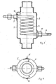
- a cylindrical heat exchanger housing 1 of the device shown has hose connection pieces 2 on both ends of the housing in order to be able to be used directly in the coolant line between a liquid-cooled engine and an engine cooler, in particular in motor vehicles, and to be directly flowed through by the coolant.
- the housing 1 has stepped connecting pieces 2, 3 on both end faces, in order to be able to attach coolant hoses with different diameters occurring in practice in motor vehicles and to clamp them by means of hose clamps.
- a helical coil 4 is arranged in the longitudinal direction of the housing, the turns of which are spaced from one another, so that the turns of the tubular coil can be intensively flowed around by the cooling liquid and can absorb heat from the cooling liquid in order to heat a liquid flowing through the coil, such as B. the wash water for the windshield washer of a motor vehicle.
- the device can also with great advantage Part are used to continuously preheat the diesel fuel for a diesel engine to such an extent that the diesel fuel remains optimally flowable and atomisable, especially in the cold season, and thereby burns fuel-economically and environmentally friendly with low soot in the diesel engine without additional energy expenditure with the already available heat of the engine cooling water can be.
- the housing 1 is divided axially into two semi-cylindrical shells 5, which can be tightly connected to one another at their abutting longitudinal edges.
- the housing 1 has two radial bushings 7 through which the radially directed connection ends 8 of the coiled tubing 4 can be passed.
- the two bushings 7 have the same type as the ends 8 of the coiled tubing 4 in opposite radial directions and the bushings 7 are arranged on the circumference of both housing shells 5.
- the ends 8 of the coiled tubing 4 can also point in the same radial direction, so that the two bushings 7 can accordingly be arranged in the same radial direction on the circumference of only one housing shell 5.
- the coiled tubing 4 can be conveniently inserted between the two housing shells during assembly of the device, and the radial connecting ends 8 of the coiled tubing can thereby be used 4 can be easily inserted through the grommets 7 and then in a simple and quick assembly process using the O-rings 9 and the over union nuts 10 are properly and reliably sealed in the grommets 7.
- the housing consists of casting or injection molding material, for example plastic.
- the housing consists of a cast aluminum, such as is also used for cylinder heads, for example, and has the advantage that the two semi-cylindrical housing shells 5 have high stability and strength even at higher temperatures and can be tightly clamped or pressed together at their longitudinal edges.
- the two housing shells 5 have outwardly projecting tabs 11 on their longitudinal edges, on which the shells 5, with a sealing insert between their longitudinal edges, can be tightly clamped by means of clamping screws 12.
- the formation of the housing from sprayable or pourable material, in particular from cast aluminum, enables the bushings 7 to be cast tightly, non-rotatably and longitudinally immovably into the shell wall during the manufacture of the shells 5. So that the grommets 7 z. B. when unscrewing the union nuts 10 do not twist or move longitudinally in the shell wall and thereby lose their tightness in the shell wall, the grommets 7 at their end cast in the shell wall, for example with a twisting circumferential knurling 13 and a longitudinal displacement-preventing constriction 14 be provided.
- the two semi-cylindrical housing shells 5 are made of sheet metal.
- the longitudinal edges 15 of one housing shell are offset in the radial direction, in the exemplary embodiment shown in the radial direction outwards, and overlap the longitudinal edges 16 of the other housing shell.
- On the overlapping longitudinal edges are the two housing shells, after the convenient installation of the pipe fittings described with reference to FIGS. 1 and 2 del 4, tightly and firmly connected. This can be done by an adhesive known in the art of metal connections or by a solder.
- the overlapping longitudinal edges of the housing shells can be inserted into one another so far that the longitudinal edges 16 abut against the offset of the radially offset longitudinal edges 15, as a result of which the overlap gap between the longitudinal edges 15 and 16 to the housing interior is sufficiently sealed to allow liquid solder to flow through to the housing interior to prevent it.
- the bushings 7 are, preferably from the inside of the housing, inserted through holes in the sheet metal wall of the housing shells 5 and rest on the inside of the sheet metal wall with a flange-like fastening shoulder 17 formed on the bushings.
- the grommets 7 can be fastened by a screwed-on lock nut lying on the outside of the sheet metal wall, and a sealing washer can be provided for sealing the grommet in the sheet metal wall hole between the fastening shoulder 17 and the sheet metal wall.
- the tight attachment of the bushing 7 to the sheet metal wall of the housing shell 5 can be done in mechanical production in that the fastening shoulder 17 has a ring 18 surrounding the bushing 7, with which the fastening shoulder 17 touches the sheet metal wall and on which the fastening shoulder 17 by a Induction welding is tight and firmly connected to the sheet metal wall.
Landscapes
- Engineering & Computer Science (AREA)
- Mechanical Engineering (AREA)
- Physics & Mathematics (AREA)
- Thermal Sciences (AREA)
- General Engineering & Computer Science (AREA)
- Water Supply & Treatment (AREA)
- Heat-Exchange Devices With Radiators And Conduit Assemblies (AREA)
- Cleaning By Liquid Or Steam (AREA)
Applications Claiming Priority (4)
| Application Number | Priority Date | Filing Date | Title |
|---|---|---|---|
| DE3643245 | 1986-12-18 | ||
| DE3643245 | 1986-12-18 | ||
| DE3737241 | 1987-11-03 | ||
| DE19873737241 DE3737241A1 (de) | 1986-12-18 | 1987-11-03 | Vorrichtung fuer kraftfahrzeuge mit fluessigkeitsgekuehltem motor zum erwaermen von scheibenwaschfluessigkeit oder dergleichen |
Publications (2)
| Publication Number | Publication Date |
|---|---|
| EP0271821A2 true EP0271821A2 (fr) | 1988-06-22 |
| EP0271821A3 EP0271821A3 (fr) | 1989-07-26 |
Family
ID=25850503
Family Applications (1)
| Application Number | Title | Priority Date | Filing Date |
|---|---|---|---|
| EP87118216A Withdrawn EP0271821A3 (fr) | 1986-12-18 | 1987-12-09 | Dispositif de chauffage de liquide de lavage de vitres ou analogue pour véhicules automobiles à moteur refroidi par liquide |
Country Status (3)
| Country | Link |
|---|---|
| US (1) | US4862951A (fr) |
| EP (1) | EP0271821A3 (fr) |
| DE (1) | DE3737241A1 (fr) |
Cited By (5)
| Publication number | Priority date | Publication date | Assignee | Title |
|---|---|---|---|---|
| EP0454919A1 (fr) * | 1990-05-03 | 1991-11-06 | Cheng-Ming Wong | Dispositif de chauffage d'eau pour nettoyage de vitre de véhicule |
| FR2667932A1 (fr) * | 1990-10-12 | 1992-04-17 | Valeo Systemes Dessuyage | Dispositif de chauffage d'un liquide lave-glace, notamment pour vehicule automobile. |
| US5183099A (en) * | 1990-02-28 | 1993-02-02 | Caoutchouc Manufacture Et Plastiques S.A. | Motor vehicle windshield washer system |
| FR2680740A1 (fr) * | 1991-09-03 | 1993-03-05 | Valeo Systemes Dessuyage | Dispositif de chauffage d'un liquide de lave-glace, notamment pour un pare-brise de vehicule automobile. |
| FR2680741A1 (fr) * | 1991-09-03 | 1993-03-05 | Valeo Systemes Dessuyage | Dispositif de chauffage d'un liquide de lave-glace, notamment pour vehicule automobile. |
Families Citing this family (24)
| Publication number | Priority date | Publication date | Assignee | Title |
|---|---|---|---|---|
| US5249623A (en) * | 1987-08-29 | 1993-10-05 | Mueller Fritz | Rubber heat exchanger |
| US4944343A (en) * | 1987-08-29 | 1990-07-31 | Mueller Fritz | Apparatus for heating fuel |
| US5099909A (en) * | 1991-05-31 | 1992-03-31 | Giuseppe Barigelli | Surface type heat exchanger for heating the water feeding the windshield washer of automobiles and for heating the diesel oil |
| US5411005A (en) * | 1993-06-15 | 1995-05-02 | Bohl; Michael E. | Emissions and fuel control system and device |
| US5522453A (en) * | 1995-03-22 | 1996-06-04 | Green; Kenneth E. | Washer fluid heater |
| US5957384A (en) * | 1997-08-26 | 1999-09-28 | Lansinger; Jere Rask | Windshield heated wiping system |
| US6675437B1 (en) | 1999-12-15 | 2004-01-13 | Shawn L. York | Portable high-temperature, high-pressure washing plant |
| US6364010B1 (en) * | 2000-06-02 | 2002-04-02 | The Consortium For Technology Licensing, Ltd. | Device to provide heated washer fluid |
| US6637378B1 (en) | 2001-03-23 | 2003-10-28 | Wayel Al-Amin | Heater core preheater |
| US6591896B1 (en) * | 2002-05-23 | 2003-07-15 | Dennis Hansen | Method and system for providing a transmission fluid heat exchanger in-line with respect to an engine cooling system |
| CA2405239A1 (fr) * | 2002-09-25 | 2004-03-25 | Peter Yeung | Compartiment de chauffage de liquide de nettoyage pour hotte de cuisine |
| US8032979B2 (en) * | 2005-09-17 | 2011-10-11 | Hydramaster North America, Inc. | Heat exchanger |
| US20070095370A1 (en) * | 2005-11-03 | 2007-05-03 | Vladimir Kratser | Mobile high-temperature washing plant |
| US10221823B2 (en) * | 2006-09-13 | 2019-03-05 | John E. Traina | Method of heating and retaining heat in an internal combustion engine to improve fuel economy |
| US8925620B2 (en) | 2008-08-18 | 2015-01-06 | Tsm Corporation | Windshield washer fluid heater |
| US8550147B2 (en) | 2008-08-18 | 2013-10-08 | Clear Vision Associates, Llc | Windshield washer fluid heater and system |
| US20100200598A1 (en) * | 2009-02-09 | 2010-08-12 | Eric John Hermsen | Fuel storage tank protection system |
| US20100300394A1 (en) * | 2009-05-28 | 2010-12-02 | Gm Global Technology Operations, Inc. | Metal alloy castings with cast-in-place tubes for fluid flow |
| WO2013074129A1 (fr) * | 2011-11-03 | 2013-05-23 | Kasprzak Adam | "vaporisateur compact de carburant" miami max ii |
| DE102012211311A1 (de) * | 2012-06-29 | 2014-01-02 | Behr Gmbh & Co. Kg | Abgaswärmeübertrager |
| DE102014007048A1 (de) * | 2014-05-14 | 2015-11-19 | Eisenmann Ag | Beschichtungssystem zum Beschichten von Gegenständen |
| US20170241308A1 (en) * | 2016-02-24 | 2017-08-24 | Ford Global Technologies, Llc | Oil maintenance strategy for electrified vehicles |
| US10436354B1 (en) * | 2016-06-28 | 2019-10-08 | Mercury Plastics Llc | Reservoir and methods of forming |
| DE102017207738A1 (de) * | 2017-05-08 | 2018-11-08 | Mahle International Gmbh | Elektrische Heizeinrichtung |
Family Cites Families (13)
| Publication number | Priority date | Publication date | Assignee | Title |
|---|---|---|---|---|
| US1785159A (en) * | 1927-09-14 | 1930-12-16 | Herbert G Ullman | Heat-interchange device |
| US1853585A (en) * | 1929-07-15 | 1932-04-12 | Albert L Ritt | Automobile heater |
| US1893484A (en) * | 1932-07-26 | 1933-01-10 | Joseph S Belt | Heat exchanger |
| US2456564A (en) * | 1945-06-07 | 1948-12-14 | Muller Otto | Fluid heater |
| US2537678A (en) * | 1948-01-24 | 1951-01-09 | Koetting Fritz | Pipe joint for water heaters |
| US2663548A (en) * | 1948-03-20 | 1953-12-22 | Heat X Changer Co Inc | Beverage cooler |
| DE2112473C3 (de) * | 1971-03-16 | 1973-10-18 | Audi Nsu Auto Union Ag, 7107 Neckarsulm | Heizbare Waschvorrichtung fur Scheiben an Kraftfahrzeugen |
| US3828847A (en) * | 1973-02-14 | 1974-08-13 | Glass Lined Water Heater Co | Hot water heater |
| DE2745791A1 (de) * | 1977-10-12 | 1979-04-26 | Keppler | Waermetauscher zum heizen des scheibenwaschwassers einer kraftfahrzeug- scheibenwaschanlage |
| US4397288A (en) * | 1981-05-01 | 1983-08-09 | Phillips Temro, Inc. | Diesel fuel warmer |
| DE3232371A1 (de) * | 1982-08-31 | 1984-03-01 | Karl 8022 Grünwald Gercken | Kraftfahrzeug mit fluessigkeitsgekuehltem motor und mit heizbarer scheiben-waschvorrichtung |
| US4575003A (en) * | 1984-05-10 | 1986-03-11 | Hotshot Auto Products Inc. | Fluid heating attachment for automobile engine cooling systems |
| CA1291113C (fr) * | 1985-03-22 | 1991-10-22 | Keith Stuart Mclaren | Echangeur thermique |
-
1987
- 1987-11-03 DE DE19873737241 patent/DE3737241A1/de not_active Withdrawn
- 1987-12-09 EP EP87118216A patent/EP0271821A3/fr not_active Withdrawn
- 1987-12-18 US US07/134,935 patent/US4862951A/en not_active Expired - Fee Related
Cited By (8)
| Publication number | Priority date | Publication date | Assignee | Title |
|---|---|---|---|---|
| US5183099A (en) * | 1990-02-28 | 1993-02-02 | Caoutchouc Manufacture Et Plastiques S.A. | Motor vehicle windshield washer system |
| EP0454919A1 (fr) * | 1990-05-03 | 1991-11-06 | Cheng-Ming Wong | Dispositif de chauffage d'eau pour nettoyage de vitre de véhicule |
| FR2667932A1 (fr) * | 1990-10-12 | 1992-04-17 | Valeo Systemes Dessuyage | Dispositif de chauffage d'un liquide lave-glace, notamment pour vehicule automobile. |
| EP0481842A1 (fr) * | 1990-10-12 | 1992-04-22 | Valeo Systemes D'essuyage | Dispositif de chauffage d'un liquide de lave-glace, notamment pour véhicule automobile |
| FR2680740A1 (fr) * | 1991-09-03 | 1993-03-05 | Valeo Systemes Dessuyage | Dispositif de chauffage d'un liquide de lave-glace, notamment pour un pare-brise de vehicule automobile. |
| FR2680741A1 (fr) * | 1991-09-03 | 1993-03-05 | Valeo Systemes Dessuyage | Dispositif de chauffage d'un liquide de lave-glace, notamment pour vehicule automobile. |
| EP0531206A1 (fr) * | 1991-09-03 | 1993-03-10 | Valeo Systemes D'essuyage | Dispositif de chauffage d'un liquide de lave-glace, notamment pour véhicule automobile |
| EP0531205A1 (fr) * | 1991-09-03 | 1993-03-10 | Valeo Systemes D'essuyage | Dispositif de chauffage d'un liquide de lave-glace, notamment pour un pare-brise de véhicule automobile |
Also Published As
| Publication number | Publication date |
|---|---|
| US4862951A (en) | 1989-09-05 |
| EP0271821A3 (fr) | 1989-07-26 |
| DE3737241A1 (de) | 1988-07-28 |
Similar Documents
| Publication | Publication Date | Title |
|---|---|---|
| EP0271821A2 (fr) | Dispositif de chauffage de liquide de lavage de vitres ou analogue pour véhicules automobiles à moteur refroidi par liquide | |
| DE69100764T2 (de) | Erwärmer für Scheibenwaschflüssigkeit für Motorkühlflüssigkeitskreislauf. | |
| EP2171337B1 (fr) | Conduite a fluides surmoulee | |
| DE69613701T2 (de) | Vorrichtung zum dichten verbinden eines starren rohrendstückes mit einem schlauch und herstellungsverfahren für eine solche vorrichtung | |
| DE2831832C2 (de) | Verfahren zum dichten Verbinden von Rohren | |
| DE102016203070B3 (de) | Anschlussstutzen und Wärmemanagementmodul mit einem solchen | |
| EP0666461B2 (fr) | Raccord de tuyaux pour une boíte à eau d'un échangeur de chaleur pour véhicule automobile | |
| DE3443085A1 (de) | Doppelrohr-waermetauscher | |
| DE19711034B4 (de) | Anschlußvorrichtung für Plattenwärmetauscher, insbesondere für Kraftfahrzeuge | |
| DE10023149A1 (de) | Hochdruckkraftstoffeinspritzrohr für Dieselmotoren | |
| DE3133756C2 (de) | Doppelrohrkühler | |
| EP0102919A2 (fr) | Procédé pour le raccordement de tuyaux et le raccord correspondant | |
| EP3894733B1 (fr) | Dispositif d'étanchéité, manchon d'étanchéité et leur utilisation | |
| DD297499A5 (de) | Befestigung und befestigungsverfahren | |
| DE2948621A1 (de) | Heizvorrichtung zum erwaermen von brennstoff mit einer erhitzten fluessigkeit | |
| DE2249449A1 (de) | Anschlussvorrichtung fuer die endoeffnungen von doppelwandigen schlaeuchen | |
| EP0874141B1 (fr) | Dispositif d'aération pour le conduit menant à la pipe d'admission d'un moteur à combustion | |
| DE102004021667A1 (de) | Schlauchverbindungssystem für einen beheizbaren Schlauch | |
| DE3602891A1 (de) | Waermetauscher fuer kraftfahrzeuge | |
| DE8714630U1 (de) | Vorrichtung für Kraftfahrzeuge mit flüssigkeitsgekühltem Motor zum Erwärmen von Scheibenwaschflüssigkeit od. dgl. | |
| DE102007025406A1 (de) | Verfahren und Anordnung zur Verbindung von Leitungsenden | |
| EP3115671B1 (fr) | Raccord de transition | |
| DE3116290C2 (de) | "Verbindung eines Rohres mit einem Anschlußstück" | |
| EP1118811A2 (fr) | Conduite flexible avec un dispositif de raccordement sur au moins une extrémité | |
| DE19815167B4 (de) | Kraftstoffleitungssystem |
Legal Events
| Date | Code | Title | Description |
|---|---|---|---|
| PUAI | Public reference made under article 153(3) epc to a published international application that has entered the european phase |
Free format text: ORIGINAL CODE: 0009012 |
|
| AK | Designated contracting states |
Kind code of ref document: A2 Designated state(s): AT BE CH DE ES FR GB GR IT LI LU NL SE |
|
| PUAL | Search report despatched |
Free format text: ORIGINAL CODE: 0009013 |
|
| AK | Designated contracting states |
Kind code of ref document: A3 Designated state(s): AT BE CH DE ES FR GB GR IT LI LU NL SE |
|
| RAP1 | Party data changed (applicant data changed or rights of an application transferred) |
Owner name: MUELLER, JOERG DIETER FRITZ |
|
| RIN1 | Information on inventor provided before grant (corrected) |
Inventor name: MUELLER, FRITZ, DIPL.-ING. Inventor name: LOHRUM, ANTON |
|
| STAA | Information on the status of an ep patent application or granted ep patent |
Free format text: STATUS: THE APPLICATION IS DEEMED TO BE WITHDRAWN |
|
| 18D | Application deemed to be withdrawn |
Effective date: 19910703 |
|
| RIN1 | Information on inventor provided before grant (corrected) |
Inventor name: MUELLER, FRITZ, DIPL.-ING. Inventor name: LOHRUM, ANTON |