EP0271832A1 - Magnetoelastisches Kraftmessgerät - Google Patents
Magnetoelastisches Kraftmessgerät Download PDFInfo
- Publication number
- EP0271832A1 EP0271832A1 EP19870118360 EP87118360A EP0271832A1 EP 0271832 A1 EP0271832 A1 EP 0271832A1 EP 19870118360 EP19870118360 EP 19870118360 EP 87118360 A EP87118360 A EP 87118360A EP 0271832 A1 EP0271832 A1 EP 0271832A1
- Authority
- EP
- European Patent Office
- Prior art keywords
- holes
- bobbin
- force transducer
- magnetoelastic
- transducer according
- Prior art date
- Legal status (The legal status is an assumption and is not a legal conclusion. Google has not performed a legal analysis and makes no representation as to the accuracy of the status listed.)
- Withdrawn
Links
- 238000004804 winding Methods 0.000 claims abstract description 34
- 230000004323 axial length Effects 0.000 claims abstract description 17
- 239000007787 solid Substances 0.000 claims abstract description 13
- 230000005284 excitation Effects 0.000 claims abstract description 8
- 239000000463 material Substances 0.000 claims abstract description 4
- 239000000696 magnetic material Substances 0.000 claims description 2
- 230000007935 neutral effect Effects 0.000 abstract description 3
- 238000004519 manufacturing process Methods 0.000 description 7
- 230000004907 flux Effects 0.000 description 3
- 230000006835 compression Effects 0.000 description 2
- 238000007906 compression Methods 0.000 description 2
- 238000011161 development Methods 0.000 description 2
- 230000018109 developmental process Effects 0.000 description 2
- 230000002349 favourable effect Effects 0.000 description 2
- 238000009434 installation Methods 0.000 description 2
- 238000005259 measurement Methods 0.000 description 2
- 238000004026 adhesive bonding Methods 0.000 description 1
- 230000002153 concerted effect Effects 0.000 description 1
- 239000013078 crystal Substances 0.000 description 1
- 230000005611 electricity Effects 0.000 description 1
- 239000002783 friction material Substances 0.000 description 1
- 238000005495 investment casting Methods 0.000 description 1
- 239000002184 metal Substances 0.000 description 1
- 238000000034 method Methods 0.000 description 1
- 238000009740 moulding (composite fabrication) Methods 0.000 description 1
- 230000008569 process Effects 0.000 description 1
- 230000001681 protective effect Effects 0.000 description 1
- 238000004080 punching Methods 0.000 description 1
- QHGVXILFMXYDRS-UHFFFAOYSA-N pyraclofos Chemical compound C1=C(OP(=O)(OCC)SCCC)C=NN1C1=CC=C(Cl)C=C1 QHGVXILFMXYDRS-UHFFFAOYSA-N 0.000 description 1
- 238000005096 rolling process Methods 0.000 description 1
- 230000001502 supplementing effect Effects 0.000 description 1
Images

Classifications
-
- G—PHYSICS
- G01—MEASURING; TESTING
- G01L—MEASURING FORCE, STRESS, TORQUE, WORK, MECHANICAL POWER, MECHANICAL EFFICIENCY, OR FLUID PRESSURE
- G01L1/00—Measuring force or stress, in general
- G01L1/12—Measuring force or stress, in general by measuring variations in the magnetic properties of materials resulting from the application of stress
- G01L1/127—Measuring force or stress, in general by measuring variations in the magnetic properties of materials resulting from the application of stress by using inductive means
-
- G—PHYSICS
- G01—MEASURING; TESTING
- G01L—MEASURING FORCE, STRESS, TORQUE, WORK, MECHANICAL POWER, MECHANICAL EFFICIENCY, OR FLUID PRESSURE
- G01L1/00—Measuring force or stress, in general
- G01L1/12—Measuring force or stress, in general by measuring variations in the magnetic properties of materials resulting from the application of stress
- G01L1/125—Measuring force or stress, in general by measuring variations in the magnetic properties of materials resulting from the application of stress by using magnetostrictive means
Definitions
- the invention relates to a magnetoelastic force transducer according to the precharacterising part of Claim 1.
- a magnetoelastic force transducer is known, for example, from the SE-B-151 267.
- a transducer of the afore-mentioned type comprises a force-subjected magnetic core built up of magnetoelastic sheets, which is provided with four through-holes for windings located perpendicular to each other, one winding being an excitation winding supplied from an a.c. source for generating a magnetic flux in the core, and the other winding being a measuring winding for sensing the magnitude of the magnetic flux passing through the measuring winding.
- the magnitude of this flux depends on the magnitude of the external force applied to the core.
- EP-B-0 089 916 shows a magnetoelastic force transducer with a specially formed sheet section with a measuring part formed as a double-bent beam.
- a transducer exhibits high linear ity and low zero voltage values.
- the zero voltage of a transducer is caused by internal stresses and crystal orientation in the sheet material, which have arisen, inter alia, during the manufacturing processes of the material, for example during rolling.
- the invention aims at the design of a magnetoelastic force transducer of the above-mentioned kind, which is extremely well suited to be manufactured at low cost by automatic series production.
- the invention suggests a magnetoelastic force transducer according to the introductory part of Claim 1, which is characterized by the features of the characterizing part of Claim 1.
- the new constructive design which avoids a laminated core structure.
- the new constructive design involves a considerable simplification, as far as manufacture and installation are concerted, in relation to the prior art magnetoelastic force transducers.
- the need of such a robust and inexpensive force transducer exists everywhere in the engineering and other industry for control and supervision of various processes.
- a magnetoelastic transducer consists of two identical solid bodies the shape of which is preferably circular-cylindrical. Extending from the first circular end surface a first axial centre hole is provided with an axial length somewhat shorter than the length of the cylindrical body. A second axial centre hole with a diameter smaller than that of the above-mentioned centre hole is made in the remaining central part of the cylindrical body. This hole is provided with an internal thread.
- a concentric tubular space is provided having an axial length somewhat shorter than the length of the body.
- the inner diameter of the tubular space is adapted such that a thin cylindrical tubular wall is formed between this space and the first central hole.
- the two cylindrical bodies are to be mounted against each other in such a way that the tubular spaces are facing each other.
- the mounting together is preferably performed by means of a stud bolt with a shank diameter adapted to provide clearance in the first central hole and with a bolt dimension adapted for the threads of the smaller threaded centre hole.
- the shank of the stud bolt should have such a length as to project somewhat outwards from the assembled transducer.
- the stud bolt is suitably made of a non-magnetic material.
- a bobbin In the total tubular space that is formed when the cylindrical bodies are mounted together there is placed a bobbin, the inner diameter of which is dimensioned to fit against the outer diameter of the thin cylindrical tubular wall and the axial length of which corresponds to the axial length of the total tubular space.
- the bobbin is provided with two measuring windings wound on the bobbin in such a way that each measuring winding will be located, in the axial direction in one of the two assembled cylindrical bodies.
- the bobbin is also provided with an excitation winding disposed radially outside the measuring windings and extending over the entire axial length of the bobbin.
- the measuring windings are electrically connected in opposite, which means that the voltage induced in the windings out-balance each other as long as no force is applied, the total output voltage thus being approximately zero.
- the transducer can be changed in a very simple way for measuring tensile forces. This can be done, for example, by providing the stud bolt with a loop or the like.
- a magnetoelastic force transducer described so far will, with a certain probability, exhibit a certain residual voltage at zero applied force and will have a certain linearity imperfection.
- the two cylindrical bodies are provided with preferably two diametrically and concentrically positioned threaded holes in that end surface that comprises the opening of the first central hole. These threaded holes extend into the tubular space housing the bobbin with its windings.
- the axial length of the bobbin is made shorter than the entire axial length of the tubular space.
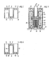
- Figures 1 and 3 show two identical, cylindrical bodies 1 and 2, with first axial centre holes 5 and 6 extending from one circular end surfaces 3 and 4, the axial length or axial depth of these holes being somewhat shorter than the axial length of the cylindrical bodies 1,2.
- Second axial centre holes 7 and 8 with threads 9 and 10 are provided in the remaining central core portion.
- Figure 2 shows the bobbin 17 on which the measuring windings 18 and 19 and the excitation winding 20 are wound.
- the inner diameter of the bobbin 17 is dimensioned for slide fit against the outer diameter of the inner cylindrical tubular wall 15.
- Figure 4 shows a magnetoelastic force transducer with the cylindrical bodies 1 and 2 from Figures 1 and 3 and the bobbin 17 from Figure 2 mounted together.
- the mounting is performed with the aid of a stud bolt 21, to which the force P to be measured is applied.
- the shank diameter of the stud bolt 21 is adapted to provide clearance in the centre hole 5 (or 6), and the stud bolt 21 has a screw thread corresponding to the threads 9 and 10 in the holes 7 and 8.
- the transducer is placed on a fixed base 22.
- the stud bolt 21 is provided with a loop or the like (not shown in Figure 4).
- FIG. 4 The basic design of a transducer according to the invention is shown in Figure 4 consisting of the three components in the Figures 1 to 3 and the stud bolt 21 that carries a threaded portion extending from its inner end face by means of which the two cylindrical bodies 1 and 2 are firmly screwed together.
- Figures 5 to 7 show a modified embodiment of a force transducer according to the invention which is provided with means for mechanical neutral point compensation.
- like numerals as in Figures 1 to 4 refer to corresponding components and portions.
- the changes necessary to afford mechanical neutral point compensation are relatively minor.
- the end surfaces 3,4 are provided with two diametrically and concentrically positioned threaded holes 43,44 and 45,46, respectively, these hole passing through the end wall into the tubular space 13,14.
- a further change consists in select ing the axial length of the bobbin 17 shorter than the total axial length of the tubular space 15,16 in the assembled force transducer.
- a first rough adjustment of the axial position of the bobbin is made while assembling the force transducer.
- the final setting of the axial position of the bobbin 17 in the transducer will be made later in connection with the calibration of the transducer.
- the position of the bobbin 17 is adjusted axially until the output signal of the transducer at zero applied force becomes zero or attains its minimum value.
- a spring 32 can be placed in the space 6 for further fine adjustment. Prestressing of the spring force is performed by with an adjusting screw 33. As shown in Figure 6, the spring 32 may consist of a coil spring or of a number of spring washers.
- the two solid bodies 1 and 2 are of cylindrical shape with the first central holes 5,6 and the bobbin having circular cross-sections and the tubular spaces 13,14 having circular cylindrical crosssections.
- this circular shape is the most favourable from the view point of manufacture, space utié lization and the uniformity of the magnetic circuit, other shapes are feasible.
- the central holes 5,6, the bobbin 17 with the windings, the thicker portion of the stud bolt, and the tubular spaces 13,14 can be used, such as other cylindrical shapes, for example an elliptical-cylindrical shape, or prismatic shapes, for example a rectangular or a square shape.
- Such shapes could be useful if the force transducers have to be posi tioned in certain limited spaces, and there manufacture could be facilitated by forming the solid bodies along with there holes and spaces by means of precision casting.
- connecting together of the two solid bodies could be effected in other ways than by means of the stud 21.
- a screw means separate from the stud 21 could be used or the cylindrical bodies could be provided with connecting flanges at their adjoining end faces.
- the hole 5 can be provided with a bearing busing of a suitable low friction material.
- the transducer can also suitably be provided with a flange of some kind or be given other possibilities for fixing it against the bases 22.
Landscapes
- Physics & Mathematics (AREA)
- General Physics & Mathematics (AREA)
- Force Measurement Appropriate To Specific Purposes (AREA)
Applications Claiming Priority (4)
| Application Number | Priority Date | Filing Date | Title |
|---|---|---|---|
| SE8605377 | 1986-12-15 | ||
| SE8605378 | 1986-12-15 | ||
| SE8605378A SE455886B (sv) | 1986-12-15 | 1986-12-15 | Magnetoelastisk kraftgivare |
| SE8605377A SE455885B (sv) | 1986-12-15 | 1986-12-15 | Magnetoelastisk kraftgivare |
Publications (1)
| Publication Number | Publication Date |
|---|---|
| EP0271832A1 true EP0271832A1 (de) | 1988-06-22 |
Family
ID=26659621
Family Applications (1)
| Application Number | Title | Priority Date | Filing Date |
|---|---|---|---|
| EP19870118360 Withdrawn EP0271832A1 (de) | 1986-12-15 | 1987-12-11 | Magnetoelastisches Kraftmessgerät |
Country Status (1)
| Country | Link |
|---|---|
| EP (1) | EP0271832A1 (de) |
Cited By (2)
| Publication number | Priority date | Publication date | Assignee | Title |
|---|---|---|---|---|
| EP0568972A3 (de) * | 1992-05-05 | 1993-11-24 | Asea Brown Boveri Ab | Magnetostriktiver Kraftwandler |
| WO2011144995A1 (en) | 2010-05-20 | 2011-11-24 | Acomon Ag | A polymerization catalyst for polythiourethanes, polymerizable liquid composition and process for the production of organic polythiourethane glass with a high refractive index |
Citations (5)
| Publication number | Priority date | Publication date | Assignee | Title |
|---|---|---|---|---|
| US1906551A (en) * | 1930-01-08 | 1933-05-02 | Forest Alfred V De | Magnetic testing method and means |
| US3320802A (en) * | 1963-09-05 | 1967-05-23 | Schenck Gmbh Carl | Device for measuring force |
| US3681982A (en) * | 1968-09-08 | 1972-08-08 | Yaskawa Denki Seisakusho Kk | Transducer system for detecting and measuring mechanical loads or stresses |
| SU1030675A1 (ru) * | 1982-01-21 | 1983-07-23 | Уфимский авиационный институт им.Орджоникидзе | Магнитоупругий преобразователь динамических усилий |
| EP0142110A2 (de) * | 1983-11-09 | 1985-05-22 | Asea Ab | Magnetoelastisches Kraftmessgerät |
-
1987
- 1987-12-11 EP EP19870118360 patent/EP0271832A1/de not_active Withdrawn
Patent Citations (5)
| Publication number | Priority date | Publication date | Assignee | Title |
|---|---|---|---|---|
| US1906551A (en) * | 1930-01-08 | 1933-05-02 | Forest Alfred V De | Magnetic testing method and means |
| US3320802A (en) * | 1963-09-05 | 1967-05-23 | Schenck Gmbh Carl | Device for measuring force |
| US3681982A (en) * | 1968-09-08 | 1972-08-08 | Yaskawa Denki Seisakusho Kk | Transducer system for detecting and measuring mechanical loads or stresses |
| SU1030675A1 (ru) * | 1982-01-21 | 1983-07-23 | Уфимский авиационный институт им.Орджоникидзе | Магнитоупругий преобразователь динамических усилий |
| EP0142110A2 (de) * | 1983-11-09 | 1985-05-22 | Asea Ab | Magnetoelastisches Kraftmessgerät |
Cited By (2)
| Publication number | Priority date | Publication date | Assignee | Title |
|---|---|---|---|---|
| EP0568972A3 (de) * | 1992-05-05 | 1993-11-24 | Asea Brown Boveri Ab | Magnetostriktiver Kraftwandler |
| WO2011144995A1 (en) | 2010-05-20 | 2011-11-24 | Acomon Ag | A polymerization catalyst for polythiourethanes, polymerizable liquid composition and process for the production of organic polythiourethane glass with a high refractive index |
Similar Documents
| Publication | Publication Date | Title |
|---|---|---|
| US4802368A (en) | Magnetoelastic force transducer | |
| EP0292718B1 (de) | Magnetoelastischer Kraftmessgeber | |
| US4825709A (en) | Magnetoelastic force transducer | |
| US5437197A (en) | Magnetostrictive sensor structures | |
| US4592234A (en) | Suspension system for a transducer | |
| CA1219633A (en) | Magnetic transducer | |
| JPS6117959A (ja) | 加速度計 | |
| US20190066902A1 (en) | Press-clamp with clamping force sensor for electric transformer winding | |
| EP0501351B1 (de) | Kraftaufnehmer | |
| GB2042183A (en) | Correction of linear errors in position measuring transducers | |
| US7228746B2 (en) | Strain-measuring device | |
| US5670753A (en) | Disc-shaped transducer for a weighing system | |
| EP0098706A2 (de) | Kraftwandler | |
| EP0568972B1 (de) | Magnetostriktiver Kraftwandler | |
| JPS5946526A (ja) | 電磁ストレスセンサ | |
| EP0221471A2 (de) | Drehmomentwandler | |
| US4287776A (en) | Force transducer | |
| US4819340A (en) | Compact focal plane precision positioning device and method | |
| US4199978A (en) | Method and apparatus for measuring mechanical forces on machine or support elements | |
| US4703208A (en) | Wristwatch stepping motor | |
| JP7422250B2 (ja) | プランジャコイル機構のための、特に電磁式の力補償の原理に基づいて作動する秤のプランジャコイル機構のための、磁気ポット | |
| US3494672A (en) | Bearings | |
| SU1296251A2 (ru) | Датчик усили прокатки | |
| JP3243124B2 (ja) | 円輪板 | |
| US4929891A (en) | Exciting unit for internal magnet type meters |
Legal Events
| Date | Code | Title | Description |
|---|---|---|---|
| PUAI | Public reference made under article 153(3) epc to a published international application that has entered the european phase |
Free format text: ORIGINAL CODE: 0009012 |
|
| AK | Designated contracting states |
Kind code of ref document: A1 Designated state(s): DE FR GB IT |
|
| 17P | Request for examination filed |
Effective date: 19881110 |
|
| 17Q | First examination report despatched |
Effective date: 19900214 |
|
| STAA | Information on the status of an ep patent application or granted ep patent |
Free format text: STATUS: THE APPLICATION HAS BEEN WITHDRAWN |
|
| 18W | Application withdrawn |
Withdrawal date: 19900623 |
|
| R18W | Application withdrawn (corrected) |
Effective date: 19900623 |