EP0271897A2 - Schnittstellenmodul für die Überlagerung von alphanumerischen Zeichen über RGB-Videosignale - Google Patents
Schnittstellenmodul für die Überlagerung von alphanumerischen Zeichen über RGB-Videosignale Download PDFInfo
- Publication number
- EP0271897A2 EP0271897A2 EP87118661A EP87118661A EP0271897A2 EP 0271897 A2 EP0271897 A2 EP 0271897A2 EP 87118661 A EP87118661 A EP 87118661A EP 87118661 A EP87118661 A EP 87118661A EP 0271897 A2 EP0271897 A2 EP 0271897A2
- Authority
- EP
- European Patent Office
- Prior art keywords
- video
- input
- video signal
- vdp
- rgb
- Prior art date
- Legal status (The legal status is an assumption and is not a legal conclusion. Google has not performed a legal analysis and makes no representation as to the accuracy of the status listed.)
- Granted
Links
Images
Classifications
-
- G—PHYSICS
- G09—EDUCATION; CRYPTOGRAPHY; DISPLAY; ADVERTISING; SEALS
- G09G—ARRANGEMENTS OR CIRCUITS FOR CONTROL OF INDICATING DEVICES USING STATIC MEANS TO PRESENT VARIABLE INFORMATION
- G09G5/00—Control arrangements or circuits for visual indicators common to cathode-ray tube indicators and other visual indicators
- G09G5/02—Control arrangements or circuits for visual indicators common to cathode-ray tube indicators and other visual indicators characterised by the way in which colour is displayed
- G09G5/026—Control of mixing and/or overlay of colours in general
Definitions
- the present invention concerns systems requiring the extension of display performances to commercial type devices, and more particularly an interface module for superimposing alphanumeric characters upon RGB video signals.
- display devices of the commercial type such as television sets or monitors
- applications different from usual video-image broadcasting is compulsory to extend new services to common TV users.
- videocommunication services with video and audio signals multiplexed in a single broad-band channel or separated; HiFi diffusive audio and video signals, recorded or interacting, forwarded by a service centre; services of participative television, where a user can generate broadcast programs.
- the structure of a broad-band network is composed of: - user's installations comprising display devices and interface modules for the connection to the distribution network; - an ISDN exchange (Integrated Services Digital Network) representing the first user's party through channel D whereupon signalling is sent both for ISDN and broad-band services, and which sends its signalling towards the broad-band exchange; - a broad-band exchange, which receives from a service centre and sends through the distribution network to users broad-band signals; as to the signalling it dialogues on one hand with the ISDN exchange and on the other hand with the service centre when the requests are to be controlled by the service centre itself; - a service centre, which is the centralized module controlling recorded and interacting services.
- ISDN exchange Integrated Services Digital Network
- a user installation to be connected to broad-band services will comprise a television set or a commercial monitor, an interface towards the broad-band exchange and an interface towards channel D of ISDN network.
- supplementary functions are demanded, such as the control of the users dialogue through data input devices such as alphanumeric keyboard, remote control, touch-screen function (if present in the display device).
- the performance of the video signal thus mixed is to be maintained at the same level as that of the original RGB signal, while low-cost and low-size requirements are to be ensured, since that interface is to be physically housed near each display device at the user's premises.
- Circuits known in the art for mixing the images and characters generally act on the image signal in the adopted TV standard, as for instance composite PAL, and operate in the TV set circuits downstream of the first intermediate frequency of the radiofrequency signal to mix the alphanumeric characters converted in turn into the same TV standard.
- An external circuit capable of carrying out a direct mixing of RGB image signals with RGB alphanumeric signals, with a resulting RGB flow, is to be avoided since it entails serious problems as to complexity, encumbrance and cost.
- an interface module for channel D of ISDN network which mixes an RGB video signal with alphanumeric characters in the adopted TV standard, e.g. composite PAL, and which allows the use of a commerical-type TV set or monitor, provided it is equipped with SCART connector it supplies with the mixed video signal.
- the interface presents total-modularity characteristics, since it allows separable functions of: input of the usual video diffusive signal through the antenna plug; input of RGB video signal with or without superimposition of alphanumeric characters, mixed with known windowing or superimposing techniques; use of data input devices such as alphanumeric keyboard, remote control, touch-screen function (if provided by the TV set); bidirectional connection on channel D of ISDN network.
- the present invention provides the interface module described in claim 1.
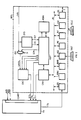
- FIG.1 denotes a video monitor or a television set of the commercial type, of whatever known type, provided it is equipped with the SCART connector.
- SCART connector inputs are defined in EN50049 specification adopted on the 27 October 1982 at Athens by CENELEC (European Committee for Electrotechnical Standardization); said specification, in addition to nominal voltage and impedance values, defines the following possible inputs, denotes also in Fig.1: - an audio input AUD of the monophonic or of the stereophonic type; - an RGB input of the three primary colour components of red, green and blue video signal, in base band without synchronization; - a VID input of a composite PAL video signal, which can consist of the single composite video signal, or of a complete base-band signal; - a fast switching signal CV, which selects VID or RGB inputs according to its polarity; - a slow switching signal CL, which chooses for TV the input either from SCART connection or from ordinary TV antenna, not shown in the figure.
- TV can also be equipped with the auxiliary function known in the art as "touch-screen”: by touching with the fingers the screen at determined points, an internal TV set circuitry generates a signal, supplied at the auxiliary output TS, carrying a pair of coded orthogonal coordinates identifying the touched point.
- touch-screen by touching with the fingers the screen at determined points, an internal TV set circuitry generates a signal, supplied at the auxiliary output TS, carrying a pair of coded orthogonal coordinates identifying the touched point.
- MTS indicates by a dashed line the interface module provided by the invention.
- MTS is to generate either the simple composite image synchronism signal for TV set, or PAL-composite image signal, partly or totally replacing the signal possibly present at RGB input.
- Said image signal consists of alphanumeric character sequences appearing on the screen as a consequence of dialogue procedures appearing on the screen as a consequence of dialogue procedures providing one or more data inputs e.g. from alphanumeric keyboard providing one or more data inputs e.g. from alphanumeric keyboard TAST, from remote control TELC, from output TS of "touch-screen" of TV set.
- Said procedures also comprise bidirectional dialogue, through bus S, with an exchange of ISDN network on digital subscriber line called "channel D".
- MTS comprises circuit blocks hereinbelow described and surrounded in Fig. 1 by the dashed line.
- ENC denotes a video-colour image encoder, which converts RGB video signal it receives at the input, consisting of composite synchronism SYN1 and of the three primary colour components R (red), G (green) and B (blue), into a composite-PAL video signal it supplies at the input VID of SCART connector.
- ENC can be implemented with TEA2000 component made by Mullard Limited.
- MX1 denotes a common multiplexer which sends onto SYN1 external composite synchronism signal SYN, or composite synchronism signal SCM generated by block VDP. MX1 is controlled by block VDP. MX1 is controlled by selecting signal S1 generated by block CPU.
- SYD denotes a known block separating frame and line synchronism signals from composite synchronism SYN.
- Line SLL and frame SCT synchronism signals are supplied to block VDP.
- Block SYD can be implemented with an integrated circuit indicated by SN96533 made by Texas Instruments.
- VDP denotes a block carrying out the known function of video image processor, i.e. of generator of video signals relevant to alphanumeric characters to be visualized on the screen.
- VDP addresses during reading and writing phases a video memory MEMV containing the coding of alphanumeric characters, and dialogues in bidirectional way with a data processing unit CPU whereby it is controlled.
- VDP generates composite synchronism signal SCM, the three primary colour components R, G, B of the video signal relevant to alphanumeric characters, and fast switching signal CV.
- VDP can be implemented with the integrated circuit indicated by TMS3556, made by Texas Instruments; said firm supplies also a data sheet of the component wherefrom useful information to implement the dialogue between VDP and memory MEMV and processing unit CPU can be obtained.
- CPU indicates the data processing unit which is to decode the information coming from the various data inputs, such as TELC, TAST, bus S, TS and to control VDP so as to generate the video signal relevant to alphanumeric characters.
- BI denotes a bus inside the CPU, which is connected to various circuit blocks described hereinbelow.
- ROM1 denotes a known-type ROM containing the microprogram executed by CPU, which will be described hereinafter.
- RAM1 denotes a known-type RAM memory for data.
- PIC denotes a known-type circuit, which controls the interrupt signals activating corresponding operative modules of the microprogram.
- PIT denotes a known-type module carrying out timing functions; it also generates an impulse at regular intervals which forms one of the "interrupt" signals forwarded to PIC.
- US1, US2, US3 denote known-type interface circuits which convert data flows arriving at their inputs into compatible format for the transfer onto bus BI: in addition at the presence of input data they generate an "interrupt" signal sent to block PIC.
- US1 receives the data at the output TS of touch-screen of TV set; US2 from keyboard TAST; US3 from a known-type receiver, not represented in the figure, of data coming from remote control TELC.
- US1, US2, US3 can be implemented with integrated circuits of 8274 type, made by INTEL.
- Said circuits receive and recognize characters sent asynchronously according to RS232C standard corresponding to CCITT Recommandations V4, V24, V28.
- IDC denotes a circuit acting as an interface on the line side, to allow the diagram with transmission line through bus S. Its design depends on the type of transmission line used. If the line is to be connected to ISDN network, the IDC is implemented by an integrated circuit of 79C32 type and AMD (Advanced Micro Devices), which manages levels 2 and 3 of the access protocol to channel D of ISDN network in accordance with CCITT Recommandations Q920/1, Q930/1.
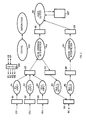
- Processing unit CPU operates according to the microprogram written in memory ROM1 in programming languages PLM86, ASM86, and subdived into operative modules hereibelow described with reference to Fig 2. This figure shows the data flow between said modules and the interested main buffer registers B1, B2,...B10 physically stored in data memory RAM1.
- microprogram is subdivided into operative modules M1, M2,...M9 controlled by a supervising module hereinafter referred to as supervisor.
- Operative modules have a number of states N corresponding to the number of pages of alphanumeric characters to be visualized on the screen.
- the states (and hence also the pages) have a tree structure starting from an initial state, corresponding to the first video page containing the first index, and which has M levels; from each state of an mth level it is possible to pass to a certain number of states of level (m+1)-th dependent on the information arriving through data input devices, (0 ⁇ m ⁇ M).
- This module is to decode the information arriving from input TS (Fig.1) of touch-screen through interface US1, which activates an interrupt signal, detected by controller PIC, and managed by the supervisor, which in turn activates module M1.
- Said information consists of an ASCII coded coordinate pair of the screen point touched by the subscriber, and is written by US1 in buffer B1.
- M1 For each state N, M1 has at its disposal in memory ROM1 (Fig.1) a table containing the coding of the screen points which, when touched, give origin to actual commands, and another table containing the codings of such commands, addressable with the first table contents.
- Module M1 at each reading in B1 of a coordinate pair, first reads in buffer B10 a coding byte of the present state allowing it to select the two tables above. Hence it checks in the first table if said coordinate pair corresponds to one of the accepted points in the present state, otherwise it does not execute the other operations and cancels the pair in B1; then it reads in the second table the command code and writes it in B5.
- This module is to decode the information arriving from keyboard TAST (Fig 1) through interface US2 which activates an interrupt signal, detected by controller PIC, and managed by the supervisor, which in turn will activate module M2.
- Said information consists of an ASCII coded command sent by the subscriber and is written by US2 in buffer B2.
- M2 For each state N, M2 has at its disposal in memory ROM1 (Fig.1) a table containing the coding of said commands.
- Module M2 at each reading in B2, first reads in buffer B10 the coding of the present state allowing it to select one of said tables . Hence, by B2 contents it addresses the table wherefrom it extracts a command it writes into buffer B5.
- command tables used by modules M1 and M2 have a different structure, since the information useful to their addressing is different, but they contain commands coded in the same way, such as to uniform the criterion by which they will be interpreted.
- This module carries out functions analogous to those of module M2, but they are devoted to decode the information arriving from remote control TELC (Fig.1) through interface US3 which activates an interrupt signal, forwarded to controller PIC and managed by the supervisor which will activate M3.
- Said information is written by US3 into buffer B3 and consists of a coding of commands sent to the subscriber which may be written to ASCII code, as in the case of keyboard TAST, or in another code more convenient to remote control.
- module M3 is to carry out preliminary operations of known type for the conversion into transmission ASCII code.
- Commands contained in B5 can be of the following two types: commands of passing to another video page (with state change) and/or commands of writing in the same video page, possibly in determined positions, of alphanumeric characters sent by the subscriber (permanence in the same state).
- the dialogue with the transmission line always provides an echo on the video screen which entails the display of characters with the already-seen modalities.
- This module is activated by the supervisor in presence of commands to be interpreted in buffer B5.
- M4 above modifies the state byte in buffer B10; then it writes in buffer B6 a coding of the new video page.
- M4 In presence of a video write command in B5, M4 does not modify B10 contents, while it writes in B6 the coding of characters to be displayed and the relevant video coordinates, besides refreshing the present video page.
- M4 writes in buffer B7 messages relevant to data read in B5 to be sent onto bus S; said messages comprise a coding heading of the message type, followed by parameters comprising the possible characters sent through video.
- the dialogue with the transmission line comprises, as already mentioned, the relevant echo on the video: hence M4 writes in B6 commands of change of page and/or writing of characters with the modalities already mentioned, besides possibly modifying state byte in B10.
- This module is activated by the supervisor in presence of messages in buffer B7.
- M5 reads in B7 and writes in buffer B4 of the FIFO type (First In First Out) messages in form readable by block IDC (fig.1); besides it supplies an activating signal to IDC which will forward it onto bus S.
- FIFO type First In First Out
- This module has the opposite task of M5, i.e. it reads in buffer B4, decodes and writes in buffer B8 the messages coming from bus S, written by interface IDC.
- M6 is activated by the supervisor upon receiving an interrupt signal generated by IDC when receiving messages form bus S.
- module M6 carries out operations equivalent to those carried out by M1, M2, M3, by reading the state byte in buffer B10 and codings of commands, to be written in B8, in convenient tables present in memory ROM1.
- This module is activated by the supervisor in presence of commands in buffer B8.
- the task of M7 is equivalent to that of M4, as to the interpretation of commands entailing page and/or character display, it writes in buffer B9, and reading and possible modification of state byte in buffer B10.
- This module has the task of managing the dialogue with block VDP (Fig.1) to sent it video-page information , on the basis of the commands read in buffers B6 or B9, and is activated by the supervisor in presence of said commands.
- the video pages at the output VID of MTS (Fig.1) have a matrix structure formed by 25 lines with 40 characters per line; each character is comprised in an 8x10-pixel matrix.
- each character is defined by a 2-byte word.
- the second byte carries the character ASCII coding, while the first defines the character properties such as colour, dimensions, display (intermittent or fixed), inversion between background and character colours, et cetera.
- Memory ROM1 (Fig.1) stores N matrices, one for each video page, carrying character definition words; some matrices have empty spaces which can be filled up with the words defining alphanumeric characters sent by the subscriber.
- Module M8 reads in ROM1 and matrix of the video page corresponding to the command present in B6 or B9 and carries it to a determined area of memory RAM1; then it adds possible characters sent by the subscriber in the positions indicated by the video coordinates present in the relevant command, then it activates the dialogue with VDP.
- microprogram which controls the dialogue with VDP, as well as the physical connections to be set with said block are known and described in the user's handbook of TMS3556 component.
- VDP in turn reads in RAM1 the matrix made by module M8 and composes in the video memory MEMV the video page to display with a known modality described in the handbook above.
- VDP can in addition forward to VDP the commands relevant to the display modalities, that VDP will handle in a known way.
- VDP will keep SCART connector, through input CV, always switched to input RGB.
- VDP will supply a signal CV which switches SCART connector onto input VID for these portions of image signal consisting of video-page alphanumeric characters, i.e. in correspondence with the whole matrix of each character (case c) or of the only significant points (case d); said signal CV switches SCART connector onto RGB input for the remaining time.
- Module M8 also supplies selection signal S1 to multiplexer MX1 (Fig.1) so that it may be switched to input SYN in case of b) type display, otherwise onto input SCM.
- M8 supplies slow switching signal CL which chooses for monitor TV and SCART connector input for all the display types a),...d).
- This module manages time-interval counting operations, executed by block PIT of Fig.1, for the check, carried out by the supervisor, on the possible overflow of processing times by the various operative modules.
- the supervisor activates M9 upon request of the other operative modules, by instance to check the reception of replies within determined time limits, and programs the counting operations M9 is to carry out.
- Operative modules processing states are: rest; ready, wherein the module is waiting for its activation; active, which corresponds to the processing phase; interrupted.
- the supervisor makes the code of the module processing state correspond to the code identifying the operative module.
- the supervisor prepares a list of the operative modules in the ready state and establishes the modules execution order, which takes into account the priority level associated with each module and the presence of the relevant activation or interrupt signals.
- the supervisor controls the stuffing degree of buffers B1,...B9 and activates the various operative modules which allow said buffers to be emptied, taking also into account the following priorities: modules M6, M5, M1, M2, M3, followed by M4 or M7 (according to which of the preceding one has been served) and then M8.
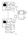
- Fig. 3 shows an example of subscriber's installation which is connected to means of a known-type network terminal NT, to a broad-band exchange (not-shown in the figure) through a bidirectional bus CLB, and to an ISDN exchange (this too not-shown in the figure) through channel D.
- Subscriber's installation is composed of a few broad-band terminals TLB1,...TLBi, as well as of ISDN terminals TERI,...TERj.
- the latter are terminals capable of dialoguing with ISDN exchange through bus S, common to all the terminals limitedly to ISDN services.
- the broad-band signals are supplied by network terminal NT on the specific channels BLB1,...BLBi to each broad-band terminal.
- each channel BLBi ther can be multiplexed: - a plurality of 70 (or 34) Mbit/s video flows - the associated audio signal - a plurality of 2 Mbit/s flows, to be used for teleconferencing or to Hi-Fi channel transmission.
- the generic broad-band terminal consists of: a commercial TV set or monitor equipped with SCART connector; an interface ILB towards the broad-band exchange of known structure, which is connected to BLB channel and supplies TV with audio signals AUD and video RGB signals (Fig.1); an interface module MTS provided by the invention which extracts composite synchronism SYN from ILB, supplies TV with signals VID, CV, CL and receives the possible signal TS, and bidirectionally connects the terminal, through bus S to channel D.
- a television camera CA can be provided for the participatory television and videocommunication function.
- a further two-input multiplexer which interrupts the bus supplying RGB signal to the homonymous input of SCART connector can be provided in interface module MTS of Fig.1: a first multiplexer input is supplied with the RGB video signal coming from outside, while the second input is supplied with the RGB signal generated by block VDP of MTS.
- the multiplexer is controlled by a signal generated by operative module M8 (Fig. 2) so that it might be switched to the input coming from VDP in a)-display mode which cuts off the image signal input from the outside; besides SCART connector is switched, through signal CV, to RGB input in correspondance with the image signal, and to input VID for the display of alphanumeric characters.
- the conversion into PAL, executed by ENC of alphanumeric characters generated in RGB by VDP is avoided with consequent ameliorated image quality, but with a cost increase of MTS.
Landscapes
- Engineering & Computer Science (AREA)
- Physics & Mathematics (AREA)
- Computer Hardware Design (AREA)
- General Physics & Mathematics (AREA)
- Theoretical Computer Science (AREA)
- Controls And Circuits For Display Device (AREA)
Applications Claiming Priority (2)
| Application Number | Priority Date | Filing Date | Title |
|---|---|---|---|
| IT8667943A IT1215206B (it) | 1986-12-18 | 1986-12-18 | Modulo interfaccia per la sovrapposizione di caratteri alfanumerici e segnale video rgb |
| IT6794386 | 1986-12-18 |
Publications (3)
| Publication Number | Publication Date |
|---|---|
| EP0271897A2 true EP0271897A2 (de) | 1988-06-22 |
| EP0271897A3 EP0271897A3 (en) | 1990-11-28 |
| EP0271897B1 EP0271897B1 (de) | 1994-06-22 |
Family
ID=11306575
Family Applications (1)
| Application Number | Title | Priority Date | Filing Date |
|---|---|---|---|
| EP87118661A Expired - Lifetime EP0271897B1 (de) | 1986-12-18 | 1987-12-16 | Schnittstellenmodul für die Überlagerung von alphanumerischen Zeichen über RGB-Videosignale |
Country Status (5)
| Country | Link |
|---|---|
| US (1) | US4800423A (de) |
| EP (1) | EP0271897B1 (de) |
| CA (1) | CA1281124C (de) |
| DE (2) | DE3750123T2 (de) |
| IT (1) | IT1215206B (de) |
Cited By (2)
| Publication number | Priority date | Publication date | Assignee | Title |
|---|---|---|---|---|
| ES2124676A1 (es) * | 1997-07-31 | 1999-02-01 | Red Nac Ferrocarriles Espan | Nuevo sistema de informacion aplicable en vehiculos de transporte de pasajeros. |
| ES2127152A1 (es) * | 1997-07-31 | 1999-04-01 | Univ Valencia Politecnica | "procedimiento de descongelacion y salado simultaneo, de piezas de carne o pescado". |
Families Citing this family (15)
| Publication number | Priority date | Publication date | Assignee | Title |
|---|---|---|---|---|
| JP2829958B2 (ja) * | 1988-01-27 | 1998-12-02 | ソニー株式会社 | タイトル画像挿入装置 |
| US5555030A (en) * | 1989-10-20 | 1996-09-10 | Accom, Inc. | Component video signal to composite video signal encoding system, control system and method |
| DE3940812A1 (de) * | 1989-12-09 | 1991-06-13 | Thomson Brandt Gmbh | Schaltung zur einblendung von schriftzeichen in einem fernsehempfaenger |
| US5249164A (en) * | 1990-06-27 | 1993-09-28 | Koz Mark C | Digital color tv for personal computers |
| US20020091850A1 (en) | 1992-10-23 | 2002-07-11 | Cybex Corporation | System and method for remote monitoring and operation of personal computers |
| JPH08275205A (ja) * | 1995-04-03 | 1996-10-18 | Sony Corp | データ符号化/復号化方法および装置、および符号化データ記録媒体 |
| KR0150139B1 (ko) * | 1995-10-10 | 1998-10-15 | 김광호 | 오버레이 보드용 확장 피쳐 커넥터 장치 |
| KR970049406A (ko) * | 1995-12-15 | 1997-07-29 | 김광호 | 그래픽 오버레이속도 향상기능을 갖는 화상처리장치 |
| US5790201A (en) * | 1996-08-08 | 1998-08-04 | Antos; Jeffrey David | Television and computer capability integration |
| US6084638A (en) * | 1996-10-08 | 2000-07-04 | Hare; Charles S. | Computer interface extension system and method |
| WO2000017766A2 (en) * | 1998-09-22 | 2000-03-30 | Cybex Computer Products Corporation | System for accessing personal computers remotely |
| US20040215742A1 (en) * | 2003-03-04 | 2004-10-28 | Soronti, Inc. | Image perfection for virtual presence architecture (VPA) |
| CN1297873C (zh) * | 2003-12-29 | 2007-01-31 | 劲永国际股份有限公司 | 可携式数字影像信号处理装置 |
| US8054294B2 (en) | 2006-03-31 | 2011-11-08 | Sony Corporation | Touch screen remote control system for use in controlling one or more devices |
| CN101599054B (zh) * | 2009-06-22 | 2011-05-25 | 哈尔滨工业大学 | 应用Mohr圆计算方法的应力求解器 |
Family Cites Families (9)
| Publication number | Priority date | Publication date | Assignee | Title |
|---|---|---|---|---|
| US4243984A (en) * | 1979-03-08 | 1981-01-06 | Texas Instruments Incorporated | Video display processor |
| US4374395A (en) * | 1980-12-24 | 1983-02-15 | Texas Instruments Incorporated | Video system with picture information and logic signal multiplexing |
| US4425581A (en) * | 1981-04-17 | 1984-01-10 | Corporation For Public Broadcasting | System for overlaying a computer generated video signal on an NTSC video signal |
| SE428161B (sv) * | 1981-10-14 | 1983-06-06 | Philips Svenska Ab | Anleggning for atergivning av valbar bakgrundsinformation kombinerad med valbar overlagringsinformation pa en bildskermsanordning samt anvendning av en dylik presentationsanleggning |
| US4599611A (en) * | 1982-06-02 | 1986-07-08 | Digital Equipment Corporation | Interactive computer-based information display system |
| US4460918A (en) * | 1982-07-14 | 1984-07-17 | Zenith Electronics Corporation | Automatic switching circuit for a dual mode television receiver |
| US4496976A (en) * | 1982-12-27 | 1985-01-29 | Rockwell International Corporation | Reduced memory graphics-to-raster scan converter |
| US4532540A (en) * | 1983-03-28 | 1985-07-30 | Rca Corporation | Teletext set-top converter with transparent mode |
| US4644401A (en) * | 1984-10-29 | 1987-02-17 | Morris K. Mirkin | Apparatus for combining graphics and video images in multiple display formats |
-
1986
- 1986-12-18 IT IT8667943A patent/IT1215206B/it active
-
1987
- 1987-11-06 US US07/118,579 patent/US4800423A/en not_active Expired - Fee Related
- 1987-12-16 EP EP87118661A patent/EP0271897B1/de not_active Expired - Lifetime
- 1987-12-16 DE DE3750123T patent/DE3750123T2/de not_active Expired - Fee Related
- 1987-12-16 DE DE198787118661T patent/DE271897T1/de active Pending
- 1987-12-17 CA CA000554680A patent/CA1281124C/en not_active Expired - Lifetime
Cited By (3)
| Publication number | Priority date | Publication date | Assignee | Title |
|---|---|---|---|---|
| ES2124676A1 (es) * | 1997-07-31 | 1999-02-01 | Red Nac Ferrocarriles Espan | Nuevo sistema de informacion aplicable en vehiculos de transporte de pasajeros. |
| WO1999006986A1 (es) * | 1997-07-31 | 1999-02-11 | Red Nacional De Los Ferrocarriles Españoles (Renfe) | Nuevo sistema de informacion aplicable en vehiculos de transporte de pasajeros |
| ES2127152A1 (es) * | 1997-07-31 | 1999-04-01 | Univ Valencia Politecnica | "procedimiento de descongelacion y salado simultaneo, de piezas de carne o pescado". |
Also Published As
| Publication number | Publication date |
|---|---|
| EP0271897A3 (en) | 1990-11-28 |
| IT8667943A0 (it) | 1986-12-18 |
| CA1281124C (en) | 1991-03-05 |
| DE3750123D1 (de) | 1994-07-28 |
| EP0271897B1 (de) | 1994-06-22 |
| US4800423A (en) | 1989-01-24 |
| DE3750123T2 (de) | 1994-11-17 |
| IT1215206B (it) | 1990-01-31 |
| DE271897T1 (de) | 1991-06-13 |
Similar Documents
| Publication | Publication Date | Title |
|---|---|---|
| US4800423A (en) | Interface module for superimposing alphanumeric characters upon RGB video signals | |
| US5717452A (en) | Interactive control system for multiservice installations including a television program distribution server and a PABX | |
| US5734436A (en) | Television receiving set having text displaying feature | |
| US6209021B1 (en) | System for computer supported collaboration | |
| US7623186B2 (en) | Apparatus and method for displaying a television video signal in a mobile terminal | |
| GB2395082A (en) | Mobile terminal with TV reception and display function | |
| EP0766469B1 (de) | Fernsehempfänger mit einem Dekoder für Multiplex-Texte | |
| TW307965B (de) | ||
| US5627825A (en) | Video communication apparatus | |
| EP0122098A2 (de) | Schriftabrufsystem für die selektive Einblendung von Titeln in ein Videobild | |
| SE505858C2 (sv) | Kabeltelevisionssystem | |
| EP1197093B1 (de) | Verfahren und vorrichtung zur bereitstellung von bildschirmanzeige für einen multikolorimetrie-empfänger | |
| US7212250B1 (en) | Method and apparatus for providing on-screen displays for a multi-colorimetry receiver | |
| US4783650A (en) | Data display arrangement | |
| KR100282954B1 (ko) | 단일 스트림 엠펙 동영상과 정지화상의 혼용제어방법 | |
| JPH05268381A (ja) | 画像伝送装置 | |
| JPS6464482A (en) | Television conference controller among multispots | |
| CA1256553A (en) | Digital transmission system | |
| JP3258409B2 (ja) | 通信会議装置 | |
| KR20020006958A (ko) | 신호 전송 방법 및 장치 | |
| JPH03292084A (ja) | テレビ電話装置 | |
| HK101389A (en) | Television receiver with text insertion | |
| KR960013035A (ko) | 텔레비젼의 공용수신장치 | |
| JPS58147285A (ja) | 画像情報端末装置 | |
| JPH04221998A (ja) | 画像表示方式 |
Legal Events
| Date | Code | Title | Description |
|---|---|---|---|
| PUAI | Public reference made under article 153(3) epc to a published international application that has entered the european phase |
Free format text: ORIGINAL CODE: 0009012 |
|
| AK | Designated contracting states |
Kind code of ref document: A2 Designated state(s): DE FR GB IT NL SE |
|
| PUAL | Search report despatched |
Free format text: ORIGINAL CODE: 0009013 |
|
| AK | Designated contracting states |
Kind code of ref document: A3 Designated state(s): DE FR GB IT NL SE |
|
| ET | Fr: translation filed | ||
| 17P | Request for examination filed |
Effective date: 19901221 |
|
| TCNL | Nl: translation of patent claims filed | ||
| RAP1 | Party data changed (applicant data changed or rights of an application transferred) |
Owner name: SIP SOCIETA ITALIANA PER L'ESERCIZIO DELLE TELECOM |
|
| REG | Reference to a national code |
Ref country code: DE Ref legal event code: 8580 Free format text: DER PATENTANMELDER LAUTET RICHTIG: SIP SOCIETA ITALIANA PER L'ESERCIZIO DELLE TELECOMUNICAZIONI P.A., TURIN/TORINO, IT |
|
| DET | De: translation of patent claims | ||
| 17Q | First examination report despatched |
Effective date: 19920527 |
|
| GRAA | (expected) grant |
Free format text: ORIGINAL CODE: 0009210 |
|
| AK | Designated contracting states |
Kind code of ref document: B1 Designated state(s): DE FR GB IT NL SE |
|
| REF | Corresponds to: |
Ref document number: 3750123 Country of ref document: DE Date of ref document: 19940728 |
|
| ITF | It: translation for a ep patent filed | ||
| ET | Fr: translation filed | ||
| EAL | Se: european patent in force in sweden |
Ref document number: 87118661.5 |
|
| PLBE | No opposition filed within time limit |
Free format text: ORIGINAL CODE: 0009261 |
|
| STAA | Information on the status of an ep patent application or granted ep patent |
Free format text: STATUS: NO OPPOSITION FILED WITHIN TIME LIMIT |
|
| 26N | No opposition filed | ||
| REG | Reference to a national code |
Ref country code: FR Ref legal event code: TP Ref country code: FR Ref legal event code: CD |
|
| NLS | Nl: assignments of ep-patents |
Owner name: TELECOM ITALIA S.P.A. |
|
| REG | Reference to a national code |
Ref country code: GB Ref legal event code: 732E |
|
| PGFP | Annual fee paid to national office [announced via postgrant information from national office to epo] |
Ref country code: SE Payment date: 19991122 Year of fee payment: 13 |
|
| PGFP | Annual fee paid to national office [announced via postgrant information from national office to epo] |
Ref country code: GB Payment date: 19991215 Year of fee payment: 13 |
|
| PGFP | Annual fee paid to national office [announced via postgrant information from national office to epo] |
Ref country code: DE Payment date: 19991222 Year of fee payment: 13 |
|
| PGFP | Annual fee paid to national office [announced via postgrant information from national office to epo] |
Ref country code: FR Payment date: 19991228 Year of fee payment: 13 |
|
| PGFP | Annual fee paid to national office [announced via postgrant information from national office to epo] |
Ref country code: NL Payment date: 19991231 Year of fee payment: 13 |
|
| PG25 | Lapsed in a contracting state [announced via postgrant information from national office to epo] |
Ref country code: GB Free format text: LAPSE BECAUSE OF NON-PAYMENT OF DUE FEES Effective date: 20001216 |
|
| PG25 | Lapsed in a contracting state [announced via postgrant information from national office to epo] |
Ref country code: SE Free format text: LAPSE BECAUSE OF NON-PAYMENT OF DUE FEES Effective date: 20001217 |
|
| PG25 | Lapsed in a contracting state [announced via postgrant information from national office to epo] |
Ref country code: NL Free format text: LAPSE BECAUSE OF NON-PAYMENT OF DUE FEES Effective date: 20010701 |
|
| GBPC | Gb: european patent ceased through non-payment of renewal fee |
Effective date: 20001216 |
|
| EUG | Se: european patent has lapsed |
Ref document number: 87118661.5 |
|
| PG25 | Lapsed in a contracting state [announced via postgrant information from national office to epo] |
Ref country code: FR Free format text: LAPSE BECAUSE OF NON-PAYMENT OF DUE FEES Effective date: 20010831 |
|
| NLV4 | Nl: lapsed or anulled due to non-payment of the annual fee |
Effective date: 20010701 |
|
| REG | Reference to a national code |
Ref country code: FR Ref legal event code: ST |
|
| PG25 | Lapsed in a contracting state [announced via postgrant information from national office to epo] |
Ref country code: DE Free format text: LAPSE BECAUSE OF NON-PAYMENT OF DUE FEES Effective date: 20011002 |
|
| PG25 | Lapsed in a contracting state [announced via postgrant information from national office to epo] |
Ref country code: IT Free format text: LAPSE BECAUSE OF NON-PAYMENT OF DUE FEES;WARNING: LAPSES OF ITALIAN PATENTS WITH EFFECTIVE DATE BEFORE 2007 MAY HAVE OCCURRED AT ANY TIME BEFORE 2007. THE CORRECT EFFECTIVE DATE MAY BE DIFFERENT FROM THE ONE RECORDED. Effective date: 20051216 |