EP0271978A2 - Guide de bande composite pour une cassette de magnétoscope - Google Patents
Guide de bande composite pour une cassette de magnétoscope Download PDFInfo
- Publication number
- EP0271978A2 EP0271978A2 EP87308949A EP87308949A EP0271978A2 EP 0271978 A2 EP0271978 A2 EP 0271978A2 EP 87308949 A EP87308949 A EP 87308949A EP 87308949 A EP87308949 A EP 87308949A EP 0271978 A2 EP0271978 A2 EP 0271978A2
- Authority
- EP
- European Patent Office
- Prior art keywords
- tape guide
- tape
- covering member
- guide body
- covering
- Prior art date
- Legal status (The legal status is an assumption and is not a legal conclusion. Google has not performed a legal analysis and makes no representation as to the accuracy of the status listed.)
- Granted
Links
- 239000002131 composite material Substances 0.000 title claims abstract description 19
- 239000000463 material Substances 0.000 claims abstract description 37
- 239000000696 magnetic material Substances 0.000 claims abstract description 7
- 229910001220 stainless steel Inorganic materials 0.000 claims description 13
- 239000010935 stainless steel Substances 0.000 claims description 13
- 229920003023 plastic Polymers 0.000 claims description 5
- 239000004033 plastic Substances 0.000 claims description 5
- 229910052751 metal Inorganic materials 0.000 claims description 4
- 239000002184 metal Substances 0.000 claims description 4
- 229910001369 Brass Inorganic materials 0.000 claims description 3
- VYZAMTAEIAYCRO-UHFFFAOYSA-N Chromium Chemical compound [Cr] VYZAMTAEIAYCRO-UHFFFAOYSA-N 0.000 claims description 3
- 229910000617 Mangalloy Inorganic materials 0.000 claims description 3
- 239000010951 brass Substances 0.000 claims description 3
- 229910052804 chromium Inorganic materials 0.000 claims description 3
- 239000011651 chromium Substances 0.000 claims description 3
- 239000000758 substrate Substances 0.000 claims description 3
- 229910010293 ceramic material Inorganic materials 0.000 claims description 2
- XEEYBQQBJWHFJM-UHFFFAOYSA-N Iron Chemical compound [Fe] XEEYBQQBJWHFJM-UHFFFAOYSA-N 0.000 claims 1
- 238000004519 manufacturing process Methods 0.000 description 8
- 230000009467 reduction Effects 0.000 description 5
- 230000000694 effects Effects 0.000 description 4
- 230000008901 benefit Effects 0.000 description 3
- 238000003780 insertion Methods 0.000 description 2
- 230000037431 insertion Effects 0.000 description 2
- 238000010137 moulding (plastic) Methods 0.000 description 2
- 241001052209 Cylinder Species 0.000 description 1
- 239000000919 ceramic Substances 0.000 description 1
- 230000006872 improvement Effects 0.000 description 1
- 150000002739 metals Chemical class 0.000 description 1
- 238000000034 method Methods 0.000 description 1
- 238000012986 modification Methods 0.000 description 1
- 230000004048 modification Effects 0.000 description 1
- 238000000465 moulding Methods 0.000 description 1
- 230000002265 prevention Effects 0.000 description 1
- 230000008569 process Effects 0.000 description 1
- 230000006641 stabilisation Effects 0.000 description 1
- 238000011105 stabilization Methods 0.000 description 1
- 238000004381 surface treatment Methods 0.000 description 1
Images


Classifications
-
- G—PHYSICS
- G11—INFORMATION STORAGE
- G11B—INFORMATION STORAGE BASED ON RELATIVE MOVEMENT BETWEEN RECORD CARRIER AND TRANSDUCER
- G11B23/00—Record carriers not specific to the method of recording or reproducing; Accessories, e.g. containers, specially adapted for co-operation with the recording or reproducing apparatus ; Intermediate mediums; Apparatus or processes specially adapted for their manufacture
- G11B23/02—Containers; Storing means both adapted to cooperate with the recording or reproducing means
- G11B23/04—Magazines; Cassettes for webs or filaments
- G11B23/08—Magazines; Cassettes for webs or filaments for housing webs or filaments having two distinct ends
- G11B23/087—Magazines; Cassettes for webs or filaments for housing webs or filaments having two distinct ends using two different reels or cores
- G11B23/08707—Details
- G11B23/08757—Guiding means
-
- G—PHYSICS
- G11—INFORMATION STORAGE
- G11B—INFORMATION STORAGE BASED ON RELATIVE MOVEMENT BETWEEN RECORD CARRIER AND TRANSDUCER
- G11B15/00—Driving, starting or stopping record carriers of filamentary or web form; Driving both such record carriers and heads; Guiding such record carriers or containers therefor; Control thereof; Control of operating function
- G11B15/60—Guiding record carrier
- G11B15/605—Guiding record carrier without displacing the guiding means
Definitions
- This invention relates to a tape guide, e.g. for a tape cassette for VTR.
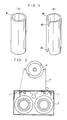
- a known tape guide 81 is shown in Fig. 1(a) of the accompanying drawings.
- Guide 81 is a stainless steel tube cut to predetermined size.
- Guide 81 has inner and outer diameters to be releasably mounted to a cassette case C (Fig. 2).
- Another known tape guide 82 is shown in Fig. (1(B).
- Guide 82 is a cylindrically rolled stainless steel plate.
- Guide 82 has four steeply bevelled corner portions providing four locating recesses 83 for preventing rotation of the guide when the guide is mounted to cassette case C.
- VTR products e.g. a tape guide
- Production costs of guides 81, 82 may be reduced: by improving a readily mouldable process, or by automatic operation to reduce labour costs.
- Manufacture of guides 81, 82 has already been almost automated; thus, improvement in processing would not provide a sharp reduction in cost.
- Current manufacture is on a large scale (e.g. hundreds of thousands or millions), so that the production cost per piece unit is insignificant; consequently, there is no alternative but to reduce costs of materials or proportions thereof.
- guides 81, 82 are wholly formed of stainless steel, of high quality (at high cost), thereby making it difficult to reduce costs and proportions of materials.
- the tape guide preserves e.g. the same high precision and anti-corrosive and wear resistant properties as the known tape guides, but provides less frictional resistance against tape.
- a first aspect of the invention provides a tape guide, e.g. for a tape cassette for VTR, characterised by: a cylindrical tape guide body of first material(s); and a covering member that is a sheet member or tape contact sheet member, the covering member sufficiently covering circumferential surface of the tape guide body, the covering being optionally at least in a range or expanse larger than surface for contacting tape, the covering member comprising second material(s) so that the tape guide is a composite tape guide, the second material(s) comprising non-magnetic materials.
- a second aspect of the invention provides a tape cassette for VTR, characterised by at least one tape guide of the first aspect of the invention.
- the tape guide body has partially stepped portion for a thickness of the covering member, the longitudinally opposite ends of the tape guide having engaging slits, e.g. four said slits, of predetermined length in the vicinity of the boundary of the stepped portion; and the covering member has circular arc of curvature sufficiently larger than the tape guide body in the circumferential direction, the covering member having at its arcuate opposite ends inwardly directed engaging rims corresponding to the slits, so that the covering member may be expanded against elasticity thereof and be mounted on the stepped portion of the tape guide body such that the rims engage the slits.
- the tape guide body may be made of inexpensive and conveniently workable material(s), e.g. plastics material(s).
- the materials for making the covering member can provide improved wear resistance and anti-corrosive properties, and less frictional resistance against tape. Some examples of such materials are: a stainless steel, a manganese steel, a ceramics material, or a substrate (e.g. a brass plate) plated with a non-magnetic hard metal (e.g. chromium).
- circumferential surface of the tape guided body (at least in a range or expanse larger than surface contacting the tape) may be covered with a covering member so as to give a composite of at least two different materials, thereby enabling improved wear resistance and anti-corrosive properties, and ensuring the same high precision as the known tape guides.
- only the tape guide portion in frictional contact with tape may be formed as a non-magnetic surface of improved wear resistance and anti-corrosive properties but of less frictional resistance against tape.
- the tape guide may be used without rotation thereof when in contact with tape.
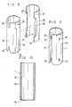
- general reference 1 represents composite tape guides.
- a composite tape guide 1 comprises: a cylindrical tape guide body 2; and a tape contact sheet member 3 of circumferential surface adapted to cover a range or expanse larger than surface contacting tape for VTR.
- Body 2 is a cylinder of predetermined inner and outer diameters.
- Body 2 has in its outer circumference a covering portion 4 stepped for a thick ness of tape contact member 3 only at surface contacting tape contact member 3.
- tape guide body 2 at its longitudinal opposite ends has four engaging slits 5 each of predetermined length.
- a portion of body 2 other than covering portion 4 has at its longitudinal opposite ends V-shaped locating recesses 6 respectively for preventing rotation of composite tape guide 1 when mounted in a cassette case C (Fig.
- Tape contact member 3 is a sheet member made of non-magnetic matterial of improved wear resistant and anti-corrosive properties, e.g. a stainless steel.
- Member 3 has a circular arc of curvature somewhat larger than a semi-circle, e.g. substantially 200 degrees in the circumferential direction of tape guide body 2.
- the curvature of member 3 is somewhat smaller than that of the covering portion 4 of tape guide body 2, so that no clearance is formed between the covering portion 4 and tape contact member 3.
- Member 3 is bent inwardly at the edges of the arcuate opposite ends 8, 8 to form engaging rims 7.
- covering tape guide body 2 with tape contact member 3 is carried out by slightly expanding the tape contact member 3 against the elasticity thereof, so as to allow mounting to the covering portion 4 and engagement of rims 7 with engaging slits 5.
- tape guide 1 is such that tape guide body 2 has 4.8 mm inner diameter and 6.0 mm outer diameter; covering portion 4 has 0.15 mm less thickness radius; and tape contact member 3 is 0.15 mm in thickness.
- Such a tape contact member 3 may conveniently be expanded and restored to its original size because of its thinness of 0.15 mm.
- Tape guide body 2 occupies a predominant portion of tape guide 1.
- Tape guide body 2 may be made of conveniently processable material(s), e.g. plastics material(s). Only an essential portion for contacting tape is covered by material(s) (e.g. a stainless steel) having non-magnetic, wear resistant, and anti-corrosive properties with less frictional resistance against tape. Thus, tape guide body 2 would never be inferior in function but be sharply reduced in cost compared with conventional tape guides 81 and 82 (Fig. 1, 2).
- the second embodiment (Fig. 6) is similar in shape to the first embodiment (Figs. 3 to 5) but is different in engagement.
- the engaging slits 5 are engaged with the engaging rims 7.
- the covering portion 14 of tape guide body 12 has engaging projections 15 each at a predetermined position in the vicinity of the stepped portions of the opposite sides, for engaging apertures 17 at confronting positions on contact member 13.
- Body 12 is mounted in the contact member 13 until edge portions or rims 18 are fitted to the stepped covering portion 14, so as to allow projections 15 to engage apertures 17, with the same effect as that of the first embodiment.
- locating recesses 16 are provided like recesses 6 in the first embodiment.
- the third embodiment there is no projection 15 nor aperture 17 of the second embodiment, but a tape contact member 23 is mounted to a covering portion 24 of a tape guide body 22.
- a possible slight divergence of tape guide body 22 against tape contact member 23 may be prevented by a curvature of contact ember 23 less than that of the covering portion 24 of the tape guide body 22, and with an enhanced elasticity.
- contact member 23 at its opposite ends is fastened to tape guide body 22 without any slippage.
- the third embodiment has the same effect as the first and second embodiments.
- a tape guide body 32 has a covering portion 34 and locating recesses 36.
- Body 32 has engaging recesses 35 at the longitudinally opposite ends of the stepped covering portion 34.
- Recesses 35 are formed by somewhat squarely expanding covering portion 34 in the circumferential direction of body 32.
- Tape contact member 33 is formed like tape contact member 23 of the third embodiment, but has at opposite ends of side edges 38 square shaped engaging projections 37 for engaging with recesses 35.
- the fifth embodiment is a composite tape guide 1 similar to the first embodiment (Figs. 3, 5), but is covered with a tape contact member 43 simultaneously with the plastic moulding of tape guide body 42.
- a tape contact member 43 simultaneously with the plastic moulding of tape guide body 42.
- An optional engagement piece 47 of suitable shape may be provided for stabilization. Locating recesses 46 may be provided.
- An optional guide groove 41 may be formed in the plastic moulding of body 42, in finishing of the surface of contact member 43.
- a plastics cylindrical tape guide body 52 with a predetermined inside diameter is covered with a tape contact sheet cylinder 53, an outer diameter of which is determined like every embodiment as above described.
- One end of tape contact cylinder 53 is inwardly squeezed to form a flange 54 for providing a journal recess with prevention of divergence when mounted on the tape guide body 52.
- the composite tape guide 1 in its entire outer circumference is covered with tape contact cylinder 53, so that a V-shaped locating recess is not required like each embodiment as above described.
- Tape contact cylinder 53 is limited to 0.15 mm or so in thickness (e.g. as in the first embodiment), thereby resulting in a negligible increase in the cost of material.
- a whole covering with tape contact cylinder 53 results in considerably improved precision, together with similar effects as those obtainable by the embodiments above described.
- a tape contact cylinder 63 has a journal recess 64 at one end (cf. 54 in Fig. 10). From an opposite end of tape contact cylinder 63, there is inserted under the pressure a cylindrical tape guide body 62 of a length shorter than an internal length of tape contact cylinder 63, and having flange 61 at one end thereof, to form a composite tape guide 1. The insertion of tape guide body 62 is constrained by flange 61 to stay only in a portion of tape contact cylinder 63. The material of tape guide body 62 may be reduced for production at a lower cost than each embodiment above described.
- a stainless steel sheet may be choked into a shape similar to tape guide body 54 or 62, so as to obtain a tape guide core cylinder for insertion into a tape contact cylinder.
- the tape guide core cylinder may be provided with a journal recess like that of the tape contact cylinder.
- the composite tape guide thus constructed may significantly reduce the material and thereby reduce the cost of material with another advantage obtainable by the sixth embodiment.
- a piping is cut into an appropriate length to provide a tape contact thin cylinder 73 for mounting around a tape guide body 72 to obtain a composite tape guide 1.
- This embodiment may give the same advantages as obtainable in each embodiment above described.
- Tape contacts members 3, 13, 23, 33 and 43 or tape contact cylinders 53, 63 and 73 may be made of manganese steel or ceramic materials to provide a composite tape guide 1 of more improved wear-resistant and anti-corrosive properties than one made of stainless steel.
- the surface of conveniently processable materials e.g. brass
- non-magnetic materials of improved wear-resistant and anti-corrosive properties, but less frictional resistance against tape e.g. hard metals for instance chromium
- Composite tape guides 1 may be mounted and fastened for use to cassette case C (Fig. 2).
- a composite tape guide 1 is adapted not to rotate within cassette case C, but is guided only through frictional contact with tape T. Even when tape T is pulled out to the position of play-back head H (Fig. 2) or even when tape T is stored within cassette case C, an angle for which the contact portion of tape T holds in relation to the composite tape guide 1 never exceeds 180 degrees, and an angular proportion of the portion where tape guide body 2 is covered by tape contact member 3 is sufficient for more than a semi-circular surface.
- cylindrical tape guide body 2 may be formed of inexpensive materials, e.g. plastics materials.
- the circumferential surface of tape guide body 2 (at least in a range or expanse larger than the surface contacting with tape T for VTR) may be covered with a sheet member of non-magnetic materials(s) (e.g. a stainless steel) of improved wear-resistant and anti-corrosive properties, but of less frictional resistance against the tape, to form a composite layer of two different materials, thereby resulting in production at a considerably reduced cost owing to use of inexpensive materials for the greater portion of cylindrical tape guide by 2 as compared with the conventional tape guides 81 and 82 formed completely of stainless steel.
- the tape guides 1 do not rotate but remain in frictional contact with the tape T in operation.
- the circumferential surface of tape guide body 2 (at least in a range or expanse larger than the surface contacting with tape for VTR) may be covered with a sheet of non-magnetic material(s) (e.g. a stainless steel) of improved wear-resistant and anti-corrosive properties, to form a composite layer of two different materials, so that an arrangement of tape guide 1 to connect tape T with the sheet may ensure a high precision like the conventional tape guides 81, 82 and a sufficient strength by covering the tape guide body 2 with the sheet.
- Expensive materials e.g. a stainless steel
- a simple manufacturing process of covering tape guide body 2 with a sheet may achieve a considerable reduction of the manufacturing cost.
Landscapes
- Registering, Tensioning, Guiding Webs, And Rollers Therefor (AREA)
Applications Claiming Priority (6)
| Application Number | Priority Date | Filing Date | Title |
|---|---|---|---|
| JP298367/86 | 1986-12-15 | ||
| JP19254686U JPS6399382U (fr) | 1986-12-15 | 1986-12-15 | |
| JP192545/86 | 1986-12-15 | ||
| JP19254586U JPS6399381U (fr) | 1986-12-15 | 1986-12-15 | |
| JP29836786A JPS63149890A (ja) | 1986-12-15 | 1986-12-15 | Vtr用カセツトテ−プの複合テ−プガイド |
| JP192546/86 | 1986-12-15 |
Publications (3)
| Publication Number | Publication Date |
|---|---|
| EP0271978A2 true EP0271978A2 (fr) | 1988-06-22 |
| EP0271978A3 EP0271978A3 (en) | 1989-05-24 |
| EP0271978B1 EP0271978B1 (fr) | 1992-06-17 |
Family
ID=27326631
Family Applications (1)
| Application Number | Title | Priority Date | Filing Date |
|---|---|---|---|
| EP87308949A Expired EP0271978B1 (fr) | 1986-12-15 | 1987-10-09 | Guide de bande composite pour une cassette de magnétoscope |
Country Status (3)
| Country | Link |
|---|---|
| US (1) | US4789114A (fr) |
| EP (1) | EP0271978B1 (fr) |
| DE (1) | DE3779884T2 (fr) |
Cited By (1)
| Publication number | Priority date | Publication date | Assignee | Title |
|---|---|---|---|---|
| EP0283560A3 (fr) * | 1987-03-25 | 1990-04-25 | KOLLER MANUFACTURING CORPORATION (a Wisconsin corporation) | Cassette à bande magnétique |
Families Citing this family (8)
| Publication number | Priority date | Publication date | Assignee | Title |
|---|---|---|---|---|
| JPH0171383U (fr) * | 1987-10-29 | 1989-05-12 | ||
| JP2668011B2 (ja) * | 1987-12-28 | 1997-10-27 | 株式会社エンプラス | 磁気テープ用ガイドポスト |
| US5201476A (en) * | 1990-05-11 | 1993-04-13 | Paul J. Gelardi | Welded video cassette |
| US5092536A (en) * | 1990-05-11 | 1992-03-03 | Paul J. Gelardi | Integrally molded recyclable video tape cassette |
| US5316234A (en) * | 1991-05-29 | 1994-05-31 | Matsushita Electric Industrial Co., Ltd. | Tape cassette for cassette recording/reproducing apparatus |
| US5333806A (en) * | 1992-06-03 | 1994-08-02 | Verbatim Corporation | Magnetic tape cartridge |
| JPH11113461A (ja) * | 1997-10-09 | 1999-04-27 | Shimano Inc | 両軸受リール |
| US20100258112A1 (en) * | 2009-04-10 | 2010-10-14 | Victory Energy Operations LLC | Generation of steam from solar energy |
Family Cites Families (13)
| Publication number | Priority date | Publication date | Assignee | Title |
|---|---|---|---|---|
| US3889900A (en) * | 1973-08-01 | 1975-06-17 | Alexander Sell Steldt & Delahu | Cartridge tape guide |
| JPS53160925U (fr) * | 1977-05-25 | 1978-12-16 | ||
| US4228940A (en) * | 1977-09-14 | 1980-10-21 | Yozaburu Umehara | Tape guide means for recording and/or reproducing apparatus and method of manufacturing the same |
| JPS5486025U (fr) * | 1977-11-24 | 1979-06-18 | ||
| DE2808998A1 (de) * | 1978-03-02 | 1979-09-13 | Bosch Gmbh Robert | Feststehende kopftrommel fuer bandaufnahme- und wiedergabegeraete |
| JPS615659Y2 (fr) * | 1980-01-14 | 1986-02-20 | ||
| JPS56115788U (fr) * | 1980-02-06 | 1981-09-04 | ||
| JPS57127951A (en) * | 1981-01-26 | 1982-08-09 | Hiroshi Nakayama | Manufacture for tape guide post of cassette for video tape recorder |
| JPS5852679U (ja) * | 1981-10-06 | 1983-04-09 | ティーディーケイ株式会社 | 磁気テ−プカ−トリツジ用テ−プガイド |
| US4545500A (en) * | 1982-12-29 | 1985-10-08 | Sony Corporation | Magnetic tape cassette |
| JPS6016388U (ja) * | 1983-07-11 | 1985-02-04 | ティーディーケイ株式会社 | 磁気テ−プカセツト |
| JPH0658758B2 (ja) * | 1984-12-24 | 1994-08-03 | バスフ アクチェン ゲゼルシャフト | テ−プ送り装置用の、特に磁気テ−プ装置用のおよびテ−プカセツト用のテ−プ案内装置 |
| JPS6242183U (fr) * | 1985-09-02 | 1987-03-13 |
-
1987
- 1987-08-14 US US07/085,206 patent/US4789114A/en not_active Expired - Fee Related
- 1987-10-09 DE DE8787308949T patent/DE3779884T2/de not_active Expired - Fee Related
- 1987-10-09 EP EP87308949A patent/EP0271978B1/fr not_active Expired
Cited By (1)
| Publication number | Priority date | Publication date | Assignee | Title |
|---|---|---|---|---|
| EP0283560A3 (fr) * | 1987-03-25 | 1990-04-25 | KOLLER MANUFACTURING CORPORATION (a Wisconsin corporation) | Cassette à bande magnétique |
Also Published As
| Publication number | Publication date |
|---|---|
| DE3779884D1 (de) | 1992-07-23 |
| EP0271978B1 (fr) | 1992-06-17 |
| DE3779884T2 (de) | 1993-01-28 |
| EP0271978A3 (en) | 1989-05-24 |
| US4789114A (en) | 1988-12-06 |
Similar Documents
| Publication | Publication Date | Title |
|---|---|---|
| US4736904A (en) | Tape guide means for a tape to be transported, in particular in a magnetic tape cassette or in a tape transport apparatus | |
| EP0271978A2 (fr) | Guide de bande composite pour une cassette de magnétoscope | |
| US4083264A (en) | Rotatable knob assembly | |
| EP0663365A4 (fr) | Support de bobine et mecanisme de rembobinage comportant un tel support. | |
| US4289282A (en) | Tape reel | |
| US4440359A (en) | Cassette roller guide | |
| US4677410A (en) | Armature bearing ring for an electromagnet | |
| US2973159A (en) | Friction reducing tape reel | |
| JPS6327341Y2 (fr) | ||
| US5167378A (en) | Video cassette reel insert for varying tape storage capacity | |
| JP3977585B2 (ja) | 基板収容ケース | |
| US5511736A (en) | Tape cassette and guide pin | |
| US5299754A (en) | Ferromagnetic insert for use with a magnetic tape cartridge and method of manufacturing the same | |
| JP2004114200A (ja) | ロータリダイカッタ用の打抜き刃および抜き孔形成刃 | |
| JPH0293110A (ja) | 止め輪 | |
| JP3023136U (ja) | 止め輪 | |
| KR101959385B1 (ko) | 폐밸트를 이용한 컨베이어 풀리 및 이의 제조방법 | |
| JP2556548Y2 (ja) | 金属線材巻取り用スプール | |
| JP3271292B2 (ja) | 磁気テープガイドの製造方法 | |
| JPS63149890A (ja) | Vtr用カセツトテ−プの複合テ−プガイド | |
| JPH05338871A (ja) | ハブ緊張用手段 | |
| JP2562728Y2 (ja) | シェル形ころ軸受 | |
| JP2607170Y2 (ja) | コンベックスルール | |
| JPH04185909A (ja) | シャフト支持装置 | |
| GB2031122A (en) | A diaphragm valve |
Legal Events
| Date | Code | Title | Description |
|---|---|---|---|
| PUAI | Public reference made under article 153(3) epc to a published international application that has entered the european phase |
Free format text: ORIGINAL CODE: 0009012 |
|
| AK | Designated contracting states |
Kind code of ref document: A2 Designated state(s): AT BE CH DE ES FR GB GR IT LI LU NL |
|
| RBV | Designated contracting states (corrected) |
Designated state(s): CH DE FR GB IT LI NL |
|
| PUAL | Search report despatched |
Free format text: ORIGINAL CODE: 0009013 |
|
| AK | Designated contracting states |
Kind code of ref document: A3 Designated state(s): CH DE FR GB IT LI NL |
|
| 17P | Request for examination filed |
Effective date: 19891013 |
|
| 17Q | First examination report despatched |
Effective date: 19901220 |
|
| GRAA | (expected) grant |
Free format text: ORIGINAL CODE: 0009210 |
|
| AK | Designated contracting states |
Kind code of ref document: B1 Designated state(s): CH DE FR GB IT LI NL |
|
| REF | Corresponds to: |
Ref document number: 3779884 Country of ref document: DE Date of ref document: 19920723 |
|
| ET | Fr: translation filed | ||
| ITF | It: translation for a ep patent filed | ||
| PG25 | Lapsed in a contracting state [announced via postgrant information from national office to epo] |
Ref country code: GB Effective date: 19921009 |
|
| PG25 | Lapsed in a contracting state [announced via postgrant information from national office to epo] |
Ref country code: LI Effective date: 19921031 Ref country code: CH Effective date: 19921031 |
|
| PLBE | No opposition filed within time limit |
Free format text: ORIGINAL CODE: 0009261 |
|
| STAA | Information on the status of an ep patent application or granted ep patent |
Free format text: STATUS: NO OPPOSITION FILED WITHIN TIME LIMIT |
|
| PG25 | Lapsed in a contracting state [announced via postgrant information from national office to epo] |
Ref country code: NL Effective date: 19930501 |
|
| 26N | No opposition filed | ||
| GBPC | Gb: european patent ceased through non-payment of renewal fee |
Effective date: 19921009 |
|
| NLV4 | Nl: lapsed or anulled due to non-payment of the annual fee | ||
| PG25 | Lapsed in a contracting state [announced via postgrant information from national office to epo] |
Ref country code: FR Effective date: 19930630 |
|
| REG | Reference to a national code |
Ref country code: CH Ref legal event code: PL |
|
| PG25 | Lapsed in a contracting state [announced via postgrant information from national office to epo] |
Ref country code: DE Effective date: 19930701 |
|
| REG | Reference to a national code |
Ref country code: FR Ref legal event code: ST |
|
| PG25 | Lapsed in a contracting state [announced via postgrant information from national office to epo] |
Ref country code: IT Free format text: LAPSE BECAUSE OF NON-PAYMENT OF DUE FEES;WARNING: LAPSES OF ITALIAN PATENTS WITH EFFECTIVE DATE BEFORE 2007 MAY HAVE OCCURRED AT ANY TIME BEFORE 2007. THE CORRECT EFFECTIVE DATE MAY BE DIFFERENT FROM THE ONE RECORDED. Effective date: 20051009 |