EP0272010A2 - A device for ejecting granular or particulate material - Google Patents
A device for ejecting granular or particulate material Download PDFInfo
- Publication number
- EP0272010A2 EP0272010A2 EP87310433A EP87310433A EP0272010A2 EP 0272010 A2 EP0272010 A2 EP 0272010A2 EP 87310433 A EP87310433 A EP 87310433A EP 87310433 A EP87310433 A EP 87310433A EP 0272010 A2 EP0272010 A2 EP 0272010A2
- Authority
- EP
- European Patent Office
- Prior art keywords
- nozzle
- air gap
- air
- flow
- particulate material
- Prior art date
- Legal status (The legal status is an assumption and is not a legal conclusion. Google has not performed a legal analysis and makes no representation as to the accuracy of the status listed.)
- Withdrawn
Links
Images

Classifications
-
- F—MECHANICAL ENGINEERING; LIGHTING; HEATING; WEAPONS; BLASTING
- F04—POSITIVE - DISPLACEMENT MACHINES FOR LIQUIDS; PUMPS FOR LIQUIDS OR ELASTIC FLUIDS
- F04F—PUMPING OF FLUID BY DIRECT CONTACT OF ANOTHER FLUID OR BY USING INERTIA OF FLUID TO BE PUMPED; SIPHONS
- F04F5/00—Jet pumps, i.e. devices in which flow is induced by pressure drop caused by velocity of another fluid flow
- F04F5/44—Component parts, details, or accessories not provided for in, or of interest apart from, groups F04F5/02 - F04F5/42
- F04F5/46—Arrangements of nozzles
- F04F5/461—Adjustable nozzles
Definitions
- the present invention relates to a device for ejecting granular or particulate material.
- Devices for ejecting granular or particulate material from supply means for such material are known in the form of an elongate device through which the material flows, the device including a nozzle for the material, the nozzle defining an air gap in the device, to which gap air is supplied whereby as a result of the Venturi effect created in the device, the flow of material through the device is enhanced or enabled.
- a device for ejecting granular or particulate material from supply means comprising an elongate body for through flow of the material, a nozzle defining within the body an air gap, and means whereby air can be supplied to the air gap and as a result of the Venturi effect created thereby in the device flow of material through the device is enhanced or enabled, characterised in that the nozzle is adjustable as regards its position in the device whereby the air gap may be adjusted.
- the provision for adjusting the air gap enables setting the gap to a value to achieve optimum flow of material through the device.
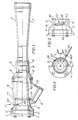
- reference numeral 1 designates an annular flange plate at an input end bolted to an annular flange connector 2 which is itself fastened by screws to a hollow body 3 having an air inlet 4 in a portion 5 of body 3 for connection to a source of compressed air.
- Body 3 is fastened by screws to a throat body 6 which is itself connected to a flared, diffuser body 7 via a locking nut 8 and a compression sleeve 9.
- Inside the body 3 is an elongate nozzle 10 defining at its innermost end an annular gap between itself and the inside face of body 6. This gap is adjustable in a manner which will be explained below, by adjusting longitudinally the position of the nozzle 10, reference numeral 11 designating an O-ring seal between nozzle 10 and body 3.
- the input end is coupled to the output of a device from which granular or particulate material is fed, for example a hopper supplied with such material.
- the material flows through the nozzle 10 and then through and out of the diffuser body 7 for subsequent handling of the material.
- the flow of the material is enabled or enhanced by supplying compressed air into inlet 4, this air emanating into the nozzle 10 through the annular gap between the innermost end of nozzle 10 and the inside face of body 6.
- the Venturi effect created where the air emanates from the annular gap the air laden with the granular or particulate material is sucked through nozzle 10 and into diffuser body 7.
- the nozzle 10 may be adjusted as regards its longitudinal position, to adjust the annular gap between its innermost end and the inner face of body 6 to achieve optimum flow of material.
- the body 3 is formed with a slot 12 through it, extending obliquely across the longitudinal axis of the ejecting device; and the nozzle 10 has two blind holes 13 and 14, these blind holes being spaced 60° apart circumferentially.
- a bar 15 is inserted into the blind hole 13 (see Figure 3) and rotated in an anti-clockwise direction in Figure 3.
- the bar 15 slides in slot 12 and, due to the latter being oblique, the nozzle 10 is pulled towards the left in Figure 1.
- the blind hole 14 appears under the above-mentioned one end of slot 12.
- the bar 15 may be inserted into the blind hole 14 and rotated again in an anti-clockwise direction in Figure 3, to pull the nozzle 10 further to the left in Figure 1.
- the bar 15 is again at the other end of slot 12, and the nozzle 10 has rotated a total of 120° and has been pulled in total from the position shown in Figure 1 to a position in which its left hand end in Figure 1 (i.e. its outermost end) is at the junction of flange plate 1 and connector 2, as shown by a broken line in Figure 1, and the annular gap is as large as permissible.
- the annular gap is set to a value which achieves optimum flow of material by adjustment of nozzle 10, the latter then being locked in place by a grub-screw 16 passing through body 3.
- Reference numeral 17 denotes a scale marked on the outside of body 3, for use in resetting the nozzle to a desired position with reference to its innermost position.
- reference numeral 18 designates the body arrangement 3/6/7 of the ejecting device
- reference numeral 19 designates a compressed air line feeding inlet 4
- reference numeral 20 denotes a hopper for feeding material to the body arrangement 3/6/7 of the device 18 via an input chamber 21.
- line 22 connected between line 19 and chamber 21 via an adjustable throttle in the form of a tap 23 for controlling the degree of air "bleed". It has been found that providing such a "bleed" of air to the material can improve the flow of material through the device 18.
Landscapes
- Engineering & Computer Science (AREA)
- Physics & Mathematics (AREA)
- Fluid Mechanics (AREA)
- Mechanical Engineering (AREA)
- General Engineering & Computer Science (AREA)
- Nozzles (AREA)
- Air Transport Of Granular Materials (AREA)
Abstract
Description
- The present invention relates to a device for ejecting granular or particulate material.
- Devices for ejecting granular or particulate material from supply means for such material (such as a hopper) are known in the form of an elongate device through which the material flows, the device including a nozzle for the material, the nozzle defining an air gap in the device, to which gap air is supplied whereby as a result of the Venturi effect created in the device, the flow of material through the device is enhanced or enabled.
- According to the present invention, there is provided a device for ejecting granular or particulate material from supply means, the device comprising an elongate body for through flow of the material, a nozzle defining within the body an air gap, and means whereby air can be supplied to the air gap and as a result of the Venturi effect created thereby in the device flow of material through the device is enhanced or enabled, characterised in that the nozzle is adjustable as regards its position in the device whereby the air gap may be adjusted. The provision for adjusting the air gap enables setting the gap to a value to achieve optimum flow of material through the device.
- The present invention will now be described, by way of example, with reference to the accompanying drawings, in which:-
- Figure 1 is a view, partly in section longitudinally, of a device for ejecting granular or particulate material;
- Figure 2 is a view in the direction of arrow Y in Figure 1;
- Figure 3 is a part section on Z-Z in Figure 2; and
- Figure 4 is a schematic diagram of an air "bleed" arrangement used with the device.
- Referring to the drawings,
reference numeral 1 designates an annular flange plate at an input end bolted to anannular flange connector 2 which is itself fastened by screws to ahollow body 3 having anair inlet 4 in a portion 5 ofbody 3 for connection to a source of compressed air.Body 3 is fastened by screws to athroat body 6 which is itself connected to a flared,diffuser body 7 via alocking nut 8 and a compression sleeve 9. Inside thebody 3 is anelongate nozzle 10 defining at its innermost end an annular gap between itself and the inside face ofbody 6. This gap is adjustable in a manner which will be explained below, by adjusting longitudinally the position of thenozzle 10,reference numeral 11 designating an O-ring seal betweennozzle 10 andbody 3. - In use of the ejecting device, the input end is coupled to the output of a device from which granular or particulate material is fed, for example a hopper supplied with such material. The material flows through the
nozzle 10 and then through and out of thediffuser body 7 for subsequent handling of the material. The flow of the material is enabled or enhanced by supplying compressed air intoinlet 4, this air emanating into thenozzle 10 through the annular gap between the innermost end ofnozzle 10 and the inside face ofbody 6. As a result of the Venturi effect created where the air emanates from the annular gap, the air laden with the granular or particulate material is sucked throughnozzle 10 and intodiffuser body 7. To control the degree of suction for a particular application, thenozzle 10 may be adjusted as regards its longitudinal position, to adjust the annular gap between its innermost end and the inner face ofbody 6 to achieve optimum flow of material. To enable such adjustment of thenozzle 10 thebody 3 is formed with aslot 12 through it, extending obliquely across the longitudinal axis of the ejecting device; and thenozzle 10 has twoblind holes nozzle 10 in the position shown in Figure 1, i.e. in its most inward position and with the narrowest possible annular gap between its innermost end and the inner face ofbody 6, theblind hole 13 underlies the slot at one end of the latter. To adjust the position ofnozzle 10 and hence the annular gap, abar 15 is inserted into the blind hole 13 (see Figure 3) and rotated in an anti-clockwise direction in Figure 3. Thebar 15 slides inslot 12 and, due to the latter being oblique, thenozzle 10 is pulled towards the left in Figure 1. After 60° of rotation, theblind hole 14 appears under the above-mentioned one end ofslot 12. To further adjust the position ofnozzle 10, thebar 15 may be inserted into theblind hole 14 and rotated again in an anti-clockwise direction in Figure 3, to pull thenozzle 10 further to the left in Figure 1. After 60° of rotation thebar 15 is again at the other end ofslot 12, and thenozzle 10 has rotated a total of 120° and has been pulled in total from the position shown in Figure 1 to a position in which its left hand end in Figure 1 (i.e. its outermost end) is at the junction offlange plate 1 andconnector 2, as shown by a broken line in Figure 1, and the annular gap is as large as permissible. In use, the annular gap is set to a value which achieves optimum flow of material by adjustment ofnozzle 10, the latter then being locked in place by a grub-screw 16 passing throughbody 3.Reference numeral 17 denotes a scale marked on the outside ofbody 3, for use in resetting the nozzle to a desired position with reference to its innermost position. - To improve the flow of material through the ejecting device, there is provided a "bleed" of air from the input to
inlet 4 to the material before it reaches the air gap of the device. Referring to Figure 4,reference numeral 18 designates thebody arrangement 3/6/7 of the ejecting device;reference numeral 19 designates a compressed airline feeding inlet 4; andreference numeral 20 denotes a hopper for feeding material to thebody arrangement 3/6/7 of thedevice 18 via aninput chamber 21. To "bleed" air fromline 19 to material before it reaches the air gap of thedevice 18, there is a line 22 connected betweenline 19 andchamber 21 via an adjustable throttle in the form of atap 23 for controlling the degree of air "bleed". It has been found that providing such a "bleed" of air to the material can improve the flow of material through thedevice 18.
Claims (4)
Applications Claiming Priority (2)
| Application Number | Priority Date | Filing Date | Title |
|---|---|---|---|
| GB8629648 | 1986-12-11 | ||
| GB08629648A GB2198480A (en) | 1986-12-11 | 1986-12-11 | Ejecting granular or particulate material |
Publications (2)
| Publication Number | Publication Date |
|---|---|
| EP0272010A2 true EP0272010A2 (en) | 1988-06-22 |
| EP0272010A3 EP0272010A3 (en) | 1988-10-05 |
Family
ID=10608858
Family Applications (1)
| Application Number | Title | Priority Date | Filing Date |
|---|---|---|---|
| EP87310433A Withdrawn EP0272010A3 (en) | 1986-12-11 | 1987-11-26 | A device for ejecting granular or particulate material |
Country Status (2)
| Country | Link |
|---|---|
| EP (1) | EP0272010A3 (en) |
| GB (1) | GB2198480A (en) |
Families Citing this family (1)
| Publication number | Priority date | Publication date | Assignee | Title |
|---|---|---|---|---|
| FR2793531B1 (en) * | 1999-05-11 | 2001-07-13 | Taema | DEVICE FOR SUCTION OF A FLUID USING AN ENGINE GAS |
Family Cites Families (3)
| Publication number | Priority date | Publication date | Assignee | Title |
|---|---|---|---|---|
| GB724292A (en) * | 1952-02-28 | 1955-02-16 | Walter Vogel | Improvements relating to stowing in mine operations |
| US3446157A (en) * | 1967-07-27 | 1969-05-27 | Schafer Davis Eng Co Inc | Means for aspirating liquid and solid materials |
| FR2141578A1 (en) * | 1971-06-17 | 1973-01-26 | Saunier Duval |
-
1986
- 1986-12-11 GB GB08629648A patent/GB2198480A/en active Pending
-
1987
- 1987-11-26 EP EP87310433A patent/EP0272010A3/en not_active Withdrawn
Also Published As
| Publication number | Publication date |
|---|---|
| GB8629648D0 (en) | 1987-01-21 |
| GB2198480A (en) | 1988-06-15 |
| EP0272010A3 (en) | 1988-10-05 |
Similar Documents
| Publication | Publication Date | Title |
|---|---|---|
| CA1284808C (en) | High speed auger venturi system and method for conveying bulk materials | |
| US3504945A (en) | Pneumatic conveyor system | |
| EP1482245B1 (en) | Device for controlling the fuel/air ratio in a premix combustion apparatus | |
| DE3865442D1 (en) | METHOD AND DEVICE FOR MICRONIZING SOLIDS IN JET MILLS. | |
| US3914093A (en) | Combustion apparatus | |
| EP0271258A2 (en) | A device for ejecting granular or particulate material | |
| US4547938A (en) | Yarn texturing jet | |
| US3973802A (en) | Conveyor line fluidizer | |
| WO1990010794A3 (en) | Fluid pump apparatus | |
| GB2198480A (en) | Ejecting granular or particulate material | |
| US5005768A (en) | Spray nozzle | |
| SE514960C2 (en) | Cellulose material feed device | |
| US4574436A (en) | Yarn texturing jet | |
| CN1006180B (en) | Self-adjusting deicer valve | |
| GB1433673A (en) | Waste grease-burning apparatus | |
| US2493387A (en) | Flow mixer | |
| EP0508164A1 (en) | Device for controlling the flow rate and/or the mixing rate of a gaseous fuel-air mixture | |
| US3685530A (en) | Flow-actuated bleed valve | |
| JPS6140500A (en) | Vacuum generator | |
| GB689680A (en) | Improvements in or relating to the pneumatic conveyance of materials | |
| GB2099778A (en) | Feeding station for pneumatic conveyors | |
| SU612872A1 (en) | Arrangement for suction withdrawal and pneumatic transportation | |
| CA2149798C (en) | Variable venturi for pneumatic conveying systems | |
| EP0066984B1 (en) | System for distributing particulate material | |
| SU992938A1 (en) | Air distributing apparatus |
Legal Events
| Date | Code | Title | Description |
|---|---|---|---|
| PUAI | Public reference made under article 153(3) epc to a published international application that has entered the european phase |
Free format text: ORIGINAL CODE: 0009012 |
|
| AK | Designated contracting states |
Kind code of ref document: A2 Designated state(s): DE FR NL |
|
| PUAL | Search report despatched |
Free format text: ORIGINAL CODE: 0009013 |
|
| AK | Designated contracting states |
Kind code of ref document: A3 Designated state(s): DE FR NL |
|
| RHK1 | Main classification (correction) |
Ipc: B65G 53/14 |
|
| RAP1 | Party data changed (applicant data changed or rights of an application transferred) |
Owner name: WESTINGHOUSE BRAKE AND SIGNAL HOLDINGS LIMITED |
|
| 17P | Request for examination filed |
Effective date: 19890206 |
|
| 17Q | First examination report despatched |
Effective date: 19900917 |
|
| STAA | Information on the status of an ep patent application or granted ep patent |
Free format text: STATUS: THE APPLICATION IS DEEMED TO BE WITHDRAWN |
|
| 18D | Application deemed to be withdrawn |
Effective date: 19910129 |
|
| RIN1 | Information on inventor provided before grant (corrected) |
Inventor name: SMALL, STEVEN ALAN Inventor name: BYE, LEONARD JAMES |