EP0272085A2 - Linsenpolierkörper - Google Patents
Linsenpolierkörper Download PDFInfo
- Publication number
- EP0272085A2 EP0272085A2 EP87311025A EP87311025A EP0272085A2 EP 0272085 A2 EP0272085 A2 EP 0272085A2 EP 87311025 A EP87311025 A EP 87311025A EP 87311025 A EP87311025 A EP 87311025A EP 0272085 A2 EP0272085 A2 EP 0272085A2
- Authority
- EP
- European Patent Office
- Prior art keywords
- pad
- lapping
- lens
- tool
- thickness
- Prior art date
- Legal status (The legal status is an assumption and is not a legal conclusion. Google has not performed a legal analysis and makes no representation as to the accuracy of the status listed.)
- Withdrawn
Links
Images

Classifications
-
- B—PERFORMING OPERATIONS; TRANSPORTING
- B24—GRINDING; POLISHING
- B24B—MACHINES, DEVICES, OR PROCESSES FOR GRINDING OR POLISHING; DRESSING OR CONDITIONING OF ABRADING SURFACES; FEEDING OF GRINDING, POLISHING, OR LAPPING AGENTS
- B24B13/00—Machines or devices designed for grinding or polishing optical surfaces on lenses or surfaces of similar shape on other work; Accessories therefor
- B24B13/01—Specific tools, e.g. bowl-like; Production, dressing or fastening of these tools
-
- Y—GENERAL TAGGING OF NEW TECHNOLOGICAL DEVELOPMENTS; GENERAL TAGGING OF CROSS-SECTIONAL TECHNOLOGIES SPANNING OVER SEVERAL SECTIONS OF THE IPC; TECHNICAL SUBJECTS COVERED BY FORMER USPC CROSS-REFERENCE ART COLLECTIONS [XRACs] AND DIGESTS
- Y10—TECHNICAL SUBJECTS COVERED BY FORMER USPC
- Y10S—TECHNICAL SUBJECTS COVERED BY FORMER USPC CROSS-REFERENCE ART COLLECTIONS [XRACs] AND DIGESTS
- Y10S451/00—Abrading
- Y10S451/921—Pad for lens shaping tool
Definitions
- This invention relates to a lens lapping pad adapted to be attached to the working surface of a tool for lapping an optical lens.
- Optical lenses are generally lapped by means of a tool having a carefully machined surface which conforms to that desired on one face of an optical lens. Sometimes the same tool has two surfaces - one for lapping one side of the lens and the other for lapping the other side of the lens. Usually the working surface or surfaces on these tools are of simple or torroidal convex or concave shape.
- lens lapping pads have comprised a metal foil of about 0.20 mm thickness, provided with an adhesive backing by which the pad is secured to a tool.
- the present invention seeks to provide a remedy.
- the present invention is directed to a lens lapping pad comprising a metal foil having a thickness substantially in the range from 0.07 mm to 0.13 mm, and a backing of cloth impregnated with a pressure sensitive adhesive, to give an overall pad thickness substantially in the range from 0.35 mm to 0.60 mm.
- Such a pad provides a further advantage that it can be readily and cleanly peeled off the tool after use.
- the invention also extends to an assembly comprising a lapping tool with a lapping pad laid on and conforming to a working surface of the lapping tool.
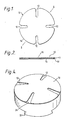
- the lens lapping pad 10 shown in Figure 1 is generally circular and has four radial slots 12 which extend inwardly from the periphery 14 of the pad, are open at the periphery 14, and are spaced uniformly around it. These slots are commonly found in lens lapping pads, and ease the fixing of an intended lower surface of the pad into close conformity with the working surface of an optical tool.
- the zinc alloy foil 16 has a thickness substantially in the range from 0.07 mm to 013 mm, and is preferably 0.10 mm thick.
- the adhesive backing 17 comprises a cloth 20 impregnated with a pressure sensitive adhesive 22.
- the backing preferably comprises "L.26X" double-sided cloth tape manufactured by Arno adhesive tapes of Victoria, England. This is a cotton cloth tape with a natural rubber based pressure sensitive adhesive on both sides. It has a thickness of about 0.35 mm, and it gives an overall thickness of the pad of about 0.45 mm.
- the pad has a thickness in the range from 0.35 mm to 0.60 mm, most preferably 0.50 mm, to conform to conventional systems, where tools have been made to allow for that thickness of pad.
- Such a pad has good flexibility because the thin foil and the cloth core of the adhesive conform well to the working surface of a tool, it is compatible with current tool systems, and peels away from the tool surface very cleanly after use.
- Figure 3 shows a lens lapping pad 10 being placed by hand onto the top of an optical tool 32.
- the lapping pad is secured to the tool working surface by hand pressure exerted on the top of the pad, to effect a bond between the pad and the tool by means of the pressure sensitive adhesive.
- an optical tool 32 has a lens lapping pad 10 like the one illustrated in Figures 1 and 2 attached to its convex working face 34.
- the protective paper cover 18 shown in Figure 2 has been peeled off and the pad has been pressed against the tool to create a bond between the lower surface 15 of the pad and the convex surface 34 of the tool by virtue of the adhesive layer 17.
- optical tool Whilst the optical tool has been shown with a convex working surface, it is to be understood that the surface could equally well be concave, for lapping a convex surface on an optical lens.
- the effective curvature of the tool shown in Figure 4 is thus determined by the convex working surface 34 itself together with an allowance for the thickness of the pad which in this case is about 1/8 dioptre.
- Figure 5 shows an assembly ready for lapping, the lapping pad 10 having been bonded to the tool 32.
- An optical lens 42 mounted on a lens-holding block 54 is held with its concave surface 50 in contact with the convex upper surface of the lens lapping pad 10, ready for the polishing operation.
- the relative movement between the tool and the block to accomplish this is usually complex, but the means which effect this movement are well known in the optical industry and are not described here in detail.
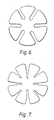
- Figure 6 is a plan view of a modified form of lens lapping pad in accordance with the present invention. This example has six radial slots.
- the further modified form illustrated in Figure 7 has eight radial slots. Alternate slots extend further towards the centre of the pad, and each slot has an inner part with parallel sides or sides converging in a direction away from the centre of the pad towards the open end of the slot, and an outer part with straight sides diverging in that direction.
- the pad may have a diameter of 75 mm.
- the lens lapping pads shown have smooth, accurate surfaces. Their thicknesses are in the range from 0.35 mm to 0.60 mm and their diameters from 50 mm to 150 mm.
- the number of slots in the illustrated examples is four, six and eight, but any number from four to eight is acceptable.
- the zinc alloy of the foil 16 is preferably made by alloying zinc of 99.95% purity with the following:- Copper .70 to .85% Titanium .10 to .12% Manganese .10 to .12% Impurities are then controlled to:- Lead .005% maximum Cadmium .003% maximum Iron .010% maximum Tin .002% maximum
Landscapes
- Engineering & Computer Science (AREA)
- Mechanical Engineering (AREA)
- Polishing Bodies And Polishing Tools (AREA)
- Grinding And Polishing Of Tertiary Curved Surfaces And Surfaces With Complex Shapes (AREA)
- Laminated Bodies (AREA)
Applications Claiming Priority (2)
| Application Number | Priority Date | Filing Date | Title |
|---|---|---|---|
| GB8630049 | 1986-12-16 | ||
| GB8630049A GB2198672B (en) | 1986-12-16 | 1986-12-16 | A lens lapping pad |
Publications (2)
| Publication Number | Publication Date |
|---|---|
| EP0272085A2 true EP0272085A2 (de) | 1988-06-22 |
| EP0272085A3 EP0272085A3 (de) | 1989-07-12 |
Family
ID=10609094
Family Applications (1)
| Application Number | Title | Priority Date | Filing Date |
|---|---|---|---|
| EP87311025A Withdrawn EP0272085A3 (de) | 1986-12-16 | 1987-12-15 | Linsenpolierkörper |
Country Status (3)
| Country | Link |
|---|---|
| US (1) | US4962618A (de) |
| EP (1) | EP0272085A3 (de) |
| GB (1) | GB2198672B (de) |
Families Citing this family (12)
| Publication number | Priority date | Publication date | Assignee | Title |
|---|---|---|---|---|
| US5210695A (en) * | 1990-10-26 | 1993-05-11 | Gerber Optical, Inc. | Single block mounting system for surfacing and edging of a lens blank and method therefor |
| US5269102A (en) * | 1991-06-19 | 1993-12-14 | Gerber Optical, Inc. | Disposable lap blank |
| US5384988A (en) * | 1993-02-05 | 1995-01-31 | Practical Systems, Inc. | Lens surfacing assembly |
| US5577950A (en) * | 1993-11-29 | 1996-11-26 | Coburn Optical Industries, Inc. | Conformal tool operating apparatus and process for an ophthalmic lens finer/polisher |
| US5895312A (en) * | 1996-10-30 | 1999-04-20 | International Business Machines Corporation | Apparatus for removing surface irregularities from a flat workpiece |
| US6089963A (en) * | 1999-03-18 | 2000-07-18 | Inland Diamond Products Company | Attachment system for lens surfacing pad |
| US6645049B2 (en) * | 2001-04-23 | 2003-11-11 | Phuong Van Nguyen | Polishing holder for silicon wafers and method of use thereof |
| US8182315B2 (en) * | 2008-03-24 | 2012-05-22 | Phuong Van Nguyen | Chemical mechanical polishing pad and dresser |
| USD603884S1 (en) | 2009-03-20 | 2009-11-10 | Michalec Ralph J | Pad for grinding or polishing ophthalmic lenses |
| DE102010019491B4 (de) * | 2010-04-30 | 2015-07-09 | Carl Zeiss Vision International Gmbh | Polierwerkzeug zur Bearbeitung von optischen Flächen, insbesondere Freiformflächen |
| US8414361B2 (en) | 2010-08-13 | 2013-04-09 | Phuong Van Nguyen | Silicon carbide, sapphire, germanium, silicon and pattern wafer polishing templates holder |
| WO2015190189A1 (ja) * | 2014-06-10 | 2015-12-17 | オリンパス株式会社 | 研磨工具、研磨方法及び研磨装置 |
Family Cites Families (14)
| Publication number | Priority date | Publication date | Assignee | Title |
|---|---|---|---|---|
| US369431A (en) * | 1887-09-06 | George e | ||
| US2752738A (en) * | 1953-09-04 | 1956-07-03 | Donald W Kent | Overlay for and method of grinding lens blanks |
| US3144737A (en) * | 1962-09-27 | 1964-08-18 | Bausch & Lomb | Aluminum foil lens grinding pad |
| US3324608A (en) * | 1965-01-27 | 1967-06-13 | Thompson Proc Co Inc | Facing assembly for lens grinding tools and the like |
| US4019289A (en) * | 1976-02-23 | 1977-04-26 | Clayton Paul Korver | Replaceable lens surfacing pad with integral wear indicating pattern |
| GB1536304A (en) * | 1976-08-20 | 1978-12-20 | Bullock Res Labor | Methods and apparatus for finishing lens surfaces |
| CH622206A5 (de) * | 1976-09-08 | 1981-03-31 | Alusuisse | |
| US4086068A (en) * | 1977-04-08 | 1978-04-25 | Minnesota Mining And Manufacturing Company | Lens grinding and polishing lap cover and method of making same |
| US4274232A (en) * | 1977-09-14 | 1981-06-23 | Minnesota Mining And Manufacturing Company | Friction grip pad |
| US4288233A (en) * | 1978-01-25 | 1981-09-08 | Wiand Ronald C | Abrasive pads for lens lapping tools |
| GB2039810B (en) * | 1979-01-17 | 1982-09-22 | J & S Wylde Ltd | Tool interfacing pad |
| GB2094824B (en) * | 1981-03-12 | 1985-07-17 | Interface Developments Ltd | Abrasive member |
| JPS5890468A (ja) * | 1981-11-16 | 1983-05-30 | Showa Denko Kk | レンズの精密研削用シ−トの製造法 |
| US4644703A (en) * | 1986-03-13 | 1987-02-24 | Norton Company | Plural layered coated abrasive |
-
1986
- 1986-12-16 GB GB8630049A patent/GB2198672B/en not_active Expired - Fee Related
-
1987
- 1987-12-15 EP EP87311025A patent/EP0272085A3/de not_active Withdrawn
-
1990
- 1990-01-19 US US07/467,182 patent/US4962618A/en not_active Expired - Fee Related
Also Published As
| Publication number | Publication date |
|---|---|
| US4962618A (en) | 1990-10-16 |
| GB2198672B (en) | 1990-10-24 |
| EP0272085A3 (de) | 1989-07-12 |
| GB2198672A (en) | 1988-06-22 |
| GB8630049D0 (en) | 1987-01-28 |
Similar Documents
| Publication | Publication Date | Title |
|---|---|---|
| US4274232A (en) | Friction grip pad | |
| US4962618A (en) | Lens lapping pad | |
| US6074290A (en) | Compliant lens block and tape | |
| US4288233A (en) | Abrasive pads for lens lapping tools | |
| ZA957039B (en) | Coated abrasive article, method for preparing the same, and method of using a coated abrasive article to abrade a hard workpiece. | |
| CA1100363A (en) | Multilayer adhesive material and method of using same for bonding bodies to one another | |
| ATE181010T1 (de) | Direkt oder indirekt mit einer maschine oder einem manuell betreibbaren schleifmittelhalter adaptierbarer schleifkörper sowie ein hierfür geeigneter adapter | |
| WO2001023141A9 (en) | Polishing pad | |
| EP0040609B1 (de) | Schleifauflage zum schleifen von linsen | |
| US4880278A (en) | Cutting tool for a mining machine | |
| JP2001510739A (ja) | ラップ仕上げ、ホーニング、およびポリッシングの間に加工部品を保持するための装置 | |
| DE3277176D1 (en) | Attaching element to be employed in grinding and polishing machines | |
| EP0353907A3 (de) | Fäserchen enthaltender Streifen und Verfahren zu dessen Herstellung | |
| GB2039810A (en) | A Tool Interfacing Pad | |
| US5626639A (en) | Abrasive articles and method of making the same | |
| CA2156199A1 (en) | Abrasive sheets | |
| US5451281A (en) | Process for imparting scratch resistance to ophthalmic lenses during edging | |
| US3522680A (en) | Expanded metal facing for a lens abrading tool | |
| CA1084271A (en) | Lens grinding and polishing lap cover | |
| AU576022B2 (en) | Coated abrasive back up pad | |
| US5605501A (en) | Lens surfacing pad with improved attachment to tool | |
| US4707950A (en) | Ring grinding tool | |
| GB2114925A (en) | Work-head and a power device including such a work-head | |
| EP1050377A3 (de) | Rotierendes Maschinen-Schleifwerkzeug | |
| US5081798A (en) | Grinding body and manufacturing procedure therefor |
Legal Events
| Date | Code | Title | Description |
|---|---|---|---|
| PUAI | Public reference made under article 153(3) epc to a published international application that has entered the european phase |
Free format text: ORIGINAL CODE: 0009012 |
|
| AK | Designated contracting states |
Kind code of ref document: A2 Designated state(s): AT BE CH DE ES FR GB GR IT LI LU NL SE |
|
| PUAL | Search report despatched |
Free format text: ORIGINAL CODE: 0009013 |
|
| AK | Designated contracting states |
Kind code of ref document: A3 Designated state(s): AT BE CH DE ES FR GB GR IT LI LU NL SE |
|
| 17P | Request for examination filed |
Effective date: 19891130 |
|
| 17Q | First examination report despatched |
Effective date: 19910222 |
|
| STAA | Information on the status of an ep patent application or granted ep patent |
Free format text: STATUS: THE APPLICATION HAS BEEN WITHDRAWN |
|
| 18W | Application withdrawn |
Withdrawal date: 19910614 |
|
| R18W | Application withdrawn (corrected) |
Effective date: 19910614 |