EP0272128A2 - Transmission à excentricité variable - Google Patents
Transmission à excentricité variable Download PDFInfo
- Publication number
- EP0272128A2 EP0272128A2 EP87311146A EP87311146A EP0272128A2 EP 0272128 A2 EP0272128 A2 EP 0272128A2 EP 87311146 A EP87311146 A EP 87311146A EP 87311146 A EP87311146 A EP 87311146A EP 0272128 A2 EP0272128 A2 EP 0272128A2
- Authority
- EP
- European Patent Office
- Prior art keywords
- shaft
- eccentric
- pulley
- rotation
- traveller
- Prior art date
- Legal status (The legal status is an assumption and is not a legal conclusion. Google has not performed a legal analysis and makes no representation as to the accuracy of the status listed.)
- Withdrawn
Links
Images

Classifications
-
- F—MECHANICAL ENGINEERING; LIGHTING; HEATING; WEAPONS; BLASTING
- F16—ENGINEERING ELEMENTS AND UNITS; GENERAL MEASURES FOR PRODUCING AND MAINTAINING EFFECTIVE FUNCTIONING OF MACHINES OR INSTALLATIONS; THERMAL INSULATION IN GENERAL
- F16H—GEARING
- F16H21/00—Gearings comprising primarily only links or levers, with or without slides
- F16H21/10—Gearings comprising primarily only links or levers, with or without slides all movement being in, or parallel to, a single plane
- F16H21/16—Gearings comprising primarily only links or levers, with or without slides all movement being in, or parallel to, a single plane for interconverting rotary motion and reciprocating motion
- F16H21/18—Crank gearings; Eccentric gearings
- F16H21/20—Crank gearings; Eccentric gearings with adjustment of throw
-
- B—PERFORMING OPERATIONS; TRANSPORTING
- B06—GENERATING OR TRANSMITTING MECHANICAL VIBRATIONS IN GENERAL
- B06B—METHODS OR APPARATUS FOR GENERATING OR TRANSMITTING MECHANICAL VIBRATIONS OF INFRASONIC, SONIC, OR ULTRASONIC FREQUENCY, e.g. FOR PERFORMING MECHANICAL WORK IN GENERAL
- B06B1/00—Methods or apparatus for generating mechanical vibrations of infrasonic, sonic, or ultrasonic frequency
- B06B1/10—Methods or apparatus for generating mechanical vibrations of infrasonic, sonic, or ultrasonic frequency making use of mechanical energy
-
- F—MECHANICAL ENGINEERING; LIGHTING; HEATING; WEAPONS; BLASTING
- F16—ENGINEERING ELEMENTS AND UNITS; GENERAL MEASURES FOR PRODUCING AND MAINTAINING EFFECTIVE FUNCTIONING OF MACHINES OR INSTALLATIONS; THERMAL INSULATION IN GENERAL
- F16C—SHAFTS; FLEXIBLE SHAFTS; ELEMENTS OR CRANKSHAFT MECHANISMS; ROTARY BODIES OTHER THAN GEARING ELEMENTS; BEARINGS
- F16C3/00—Shafts; Axles; Cranks; Eccentrics
- F16C3/04—Crankshafts, eccentric-shafts; Cranks, eccentrics
- F16C3/22—Cranks; Eccentrics
- F16C3/28—Adjustable cranks or eccentrics
-
- F—MECHANICAL ENGINEERING; LIGHTING; HEATING; WEAPONS; BLASTING
- F16—ENGINEERING ELEMENTS AND UNITS; GENERAL MEASURES FOR PRODUCING AND MAINTAINING EFFECTIVE FUNCTIONING OF MACHINES OR INSTALLATIONS; THERMAL INSULATION IN GENERAL
- F16H—GEARING
- F16H19/00—Gearings comprising essentially only toothed gears or friction members and not capable of conveying indefinitely-continuing rotary motion
- F16H19/02—Gearings comprising essentially only toothed gears or friction members and not capable of conveying indefinitely-continuing rotary motion for interconverting rotary or oscillating motion and reciprocating motion
- F16H19/06—Gearings comprising essentially only toothed gears or friction members and not capable of conveying indefinitely-continuing rotary motion for interconverting rotary or oscillating motion and reciprocating motion comprising flexible members, e.g. an endless flexible member
-
- Y—GENERAL TAGGING OF NEW TECHNOLOGICAL DEVELOPMENTS; GENERAL TAGGING OF CROSS-SECTIONAL TECHNOLOGIES SPANNING OVER SEVERAL SECTIONS OF THE IPC; TECHNICAL SUBJECTS COVERED BY FORMER USPC CROSS-REFERENCE ART COLLECTIONS [XRACs] AND DIGESTS
- Y10—TECHNICAL SUBJECTS COVERED BY FORMER USPC
- Y10T—TECHNICAL SUBJECTS COVERED BY FORMER US CLASSIFICATION
- Y10T74/00—Machine element or mechanism
- Y10T74/18—Mechanical movements
- Y10T74/18056—Rotary to or from reciprocating or oscillating
- Y10T74/18064—Head motions
Definitions
- This invention relates to an adjustable throw eccentric pulley.
- Australian patent specification No. 499,353 provides a stepless variable drive system which uses two eccentric cams which are separated by direct lateral movement of eccentrics relative to a rotating shaft to give a variable stroke. This does not directly provide a vibration and adjustment of stroke length can only be achieved when the device is stationary.
- the present invention provides an alternative method with simpler engineering to provide an eccentric drive which can be adjusted for different amounts of throw with less moving parts, and which at least in some embodiments can be adjusted while the device is working.
- the invention is said to reside in a variable eccentric drive comprising a first rotatable shaft having a first longitudinal rotational axis, an eccentric sleeve mounted for longitudinal movement on the first shaft, the sleeve having a second longitudinal axis inclined at an acute angle to the first axis, and a wheel having a third axis of rotation mounted for longitudinal movement on the sleeve, the plane of rotation of the wheel being normal to the first axis, whereby longitudinal movement of the eccentric sleeve on the first shaft changes the radial distance between the first axis and the third axis whereby altering the eccentricity of the wheel with respect to the shaft.
- the wheel may be driven by a belt or a chain or alternatively the shaft may be driven and the wheel more eccentrically.
- This can be by oppositely extending belts or by slide plates, the restraining of movement may be in one or two planes at right angles to each other.
- the invention may be said to reside in variable throw eccentric pulley arrangement comprising a first longitudinal shaft having a first longitudinal axis of rotation, a traveller on the first shaft adapted to move longitudinally along the length of the first shaft, first key and keyway means to prevent rotation of the traveller with respect to the first shaft, the outer surface of the traveller being of constant cross- section throughout its length and comprising a second shaft whose axis of rotation is inclined at an acute angle to the first longitudinal axis of rotation, and a pulley on the traveller adapted to move along the length of the traveller to rotate therewith, the pulley having its plane of rotation perpendicular to the first axis of rotation.
- the pulley by moving the pulley along the traveller which is angled to the first shaft, the distance between the centre of rotation of the first shaft in relation to the pulley can be varied so that an eccentric motion of the pulley may be obtained.
- the pulley may be a driven pulley or a driving pulley.
- the position of the pulley along the traveller may be varied and hence the amount of eccentric throw of the pulley may be varied while the pulley is in motion.
- the position of the pulley with respect to the first shaft may be fixed and the traveller may be moved with respect to both the first shaft and the pulley to vary the amount of eccentric throw of the pulley.
- thrust race bearing upon the end of the traveller to move the traveller with respect to the first shaft.
- the outer surface of the traveller may be cylindrical about the axis of rotation of the second shaft or traveller, and a second key and keyway means may be provided to prevent rotation of the pulley with respect to the shaft while allowing longitudinal movement therealong.
- the acute angle of the second shaft with respect to the first shaft may be in the range of two degrees to ten degrees, with five degrees being a preferred angle.
- the means to move the pulley along the second shaft may be adapted to be operated while the pulley is in motion, or may only be adjusted when the pulley is stationary.
- the adjustment may be by means of a screw thread or other mechanical or hydraulic system.
- the invention may be said to reside in a variable throw eccentric pulley arrangement comprising a rotatable shaft having a first longitudinal axis of rotation, a portion of the shaft comprising a shaft section having a second longitudinal axis of rotation inclined at an acute angle to the first longitudinal axis of rotation, a traveller on the shaft section adapted to be variably positioned along the length of the shaft section, and a pulley on the traveller constrained to rotate with the traveller and rotatable shaft, and having its plane of rotation perpendicular to the first longitudinal axis of rotation whereby rotation of the shaft causes eccentric rotation of the pulley.
- rotation of the pulley may cause eccentric movement of the shaft.
- the acute angle may be in the range of two degrees to ten degrees, with a preferred embodiment of five degrees.
- the portion of the shaft which includes the shaft section may be merely a cranked portion of the main shaft or it may be a section of particular shaping mounted onto the shaft.
- the shaping may be square, circular, triangular, or any other convenient shape, but to constant cross-section throughout its length so that the traveller may move along this portion of the shaft.
- the pulley may be a driven pulley or a driving pulley.
- the invention may be said to reside in a shaking frame comprising a first fixed frame and a second vibrating frame supported for vibration or eccentric motion with respect to the first frame, at least first and second rotatable shafts including first and second drive or driven pulleys mounted on the first frame towards the ends thereof, a third rotatable shaft mounted for rotation on the vibrating frame between the first and second shafts, an eccentric third drive pulley mounted on the third shaft, and drive belts between the first and third and second and third pulleys respectively, whereby rotation of the first and third shaft causes rotation of the third pulley and hence eccentric vibration of the third shaft through the eccentric third pulley, thereby vibrating the vibrating frame.
- the eccentric drive third pulley may be in any of the forms as discussed above. There may be further included a motor to drive the first or second shafts, the motor being mounted on the fixed frame.
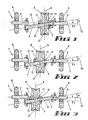
- first shaft 1 comprising sections 2 and 3 with an angled intermediate shaft 4.
- angle a the angle of the longitudinal rotational axis of the shaft 4 with respect to the shaft 1 is shown as angle a, and as discussed above the angle a may be in the range of two degrees to ten degrees, with, in a preferred embodiment five degrees.
- Shaft 1 is supported in plummer blocks 5 and 6 for rotation and may either be driven by means not shown or driven by means of a pulley as will be discussed later.
- a traveller On the angled shaft 4 a traveller may be mounted with an angled aperture through the traveller so that a pulley 8 mounted on the traveller may have its plane of rotation 9 at right angles to the axis of rotation 10 of the shaft 1.
- the actual centre of rotation of the pulley 8 is shown by the line 11.
- a keyway 12 in the second shaft and corresponding keyway 13 in the traveller and key 14, enable the traveller to move along the length of the shaft 4 but to rotate therewith.
- traveller 7 is positioned at one end of the shaft 4 so that the difference in distance between the axis of rotation of the third shaft 1 shown by 10 and the axis of rotation of the pulley shown by line 11 is the distance X and with rotation of the shaft the pulley will only vibrate a little bit.
- Locking of the traveller in a desired position is provided by locking nuts 15 and 16 on either side of the traveller.
- Belt 17 driven by pulley 8, or driving pulley 8, may in the case of being driven by pulley 8 transfer vibration to another pulley on a vibrating frame, or if a driven pulley may vibrate the shaft 1 with respect to the pulley which is driving the driven pulley 8.
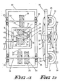
- a fixed frame 20 and a vibrating frame 21 On the fixed frame 20 a first shaft 22 is provided mounted by means of plummer blocks 23 at one end of the fixed frame, and towards the other end of a second shaft 24 mounted by plummer blocks. On shaft 22 a first pulley 26 is provided and on shaft 24 a second pulley 27, and a motor driven pulley 28 are provided.
- Plummer block 31 mount the shaft 29 onto the frame 21.
- Drive belt 32 extends from pulley 26 to eccentric pulley 33 and drive belt 34 extends from pulley 27 to eccentric pulley 33.
- Drive belt 35 extends from a motor not shown to the shaft 24 to drive the shaft 24 and hence pulley 27 and hence pulley 33 and idler pulley 28.
- the pulley 33 cannot itself move eccentrically, and as there is an eccentric drive arrangement between the pulley 33 and the shaft 29, the shaft 29 is moved eccentrically and hence moves the frame 21 so that the frame 21 moves with respect to the frame 20.
- the eccentric pulley arrangement 30 is different than that shown in the earlier embodiments and works as follows.
- spider 36 mounted to rotate with the shaft 29 and onto the pulley 33, the pulley 33 is constrained to rotate with respect to the shaft 29 but the mounting screws 37 for the spider onto the pulley 33 enable the pulley to move laterally with respect to the spider 36.
- Slotted apertures 38 are provided for this purpose in the mounting plate for the spider to the pulley 33.
- a traveller 39 is keyed by key and keyway means to the shaft 29 so that is can move along the length of the shaft 29 while rotating therewith.
- the traveller 39 is also keyed by means of key 41 to the pulley 33 so that it will rotate therewith while moving along the length of the traveller.
- the traveller is inclined at an angle to the shaft 29 so that moving the traveller with respect to both the shaft 29 and the pulley 33 will change the position of the centre of rotation of the pulley 33 with respect to the shaft 29, and hence when rotated eccentric vibration of the shaft 29 with respect to the pulley 33 will occur.
- Adjustment handle 42 is provided which acts through block 43 which has a screw threaded aperture corresponding to a screw thread on the shaft 44, so that thrust race 45 is moved along the shaft 29 and hence moves the position of the traveller 39 with respect to the shaft 29.
- a fixed frame 50 has at one end a drive shaft 51 fixed or rotating on plummer blocks 52.
- a chain wheel 53 driven by a belt 54 from a motor (not shown) drives the cog wheel 55.
- Chain 56 driven by cog wheel 55 drives eccentric wheel 57.
- Vibrating frame 58 has shaft 59 fixed for rotation.
- An eccentric sleeve 60 mounted for longitudinal movement on the shaft 59 and by means of key 61 constrained to rotate therewith.
- Thrust race 62 moved by hand wheel 63 with threaded shaft 64 in block 65 moves the eccentric sleeve longitudinally with respect to the shaft.
- the eccentric wheel 57 is mounted for longitudinal movement on the sleeve 60 but is constrained to remain fixed longitudinally with respect to the shaft 59 by means of spider 66 fixed at 67 to the shaft 59 and to the wheel at 68 while allowing transverse movement of the wheel 57 with respect to the spider 66 by means of bolt 69 sliding in slot 70.
- Ball race 83 enables the wheel 57 to turn while slides 84 fixed to the outside of the ball race 83 move laterally.
- Eccentric motion of the shaft 59 therefore only occurs at right angles to the sliding plane of the slides 84 and slides 80.
- Hand wheel 63 enables the amount of eccentric motion to be varied while the device is in motion.
Landscapes
- Engineering & Computer Science (AREA)
- General Engineering & Computer Science (AREA)
- Mechanical Engineering (AREA)
- Ocean & Marine Engineering (AREA)
- Combined Means For Separation Of Solids (AREA)
- Transmission Devices (AREA)
- Apparatuses For Generation Of Mechanical Vibrations (AREA)
- Spinning Or Twisting Of Yarns (AREA)
Applications Claiming Priority (2)
| Application Number | Priority Date | Filing Date | Title |
|---|---|---|---|
| AU9552/86 | 1986-12-17 | ||
| AUPH955286 | 1986-12-17 |
Publications (2)
| Publication Number | Publication Date |
|---|---|
| EP0272128A2 true EP0272128A2 (fr) | 1988-06-22 |
| EP0272128A3 EP0272128A3 (fr) | 1989-07-12 |
Family
ID=3771956
Family Applications (1)
| Application Number | Title | Priority Date | Filing Date |
|---|---|---|---|
| EP87311146A Withdrawn EP0272128A3 (fr) | 1986-12-17 | 1987-12-17 | Transmission à excentricité variable |
Country Status (2)
| Country | Link |
|---|---|
| US (1) | US4862756A (fr) |
| EP (1) | EP0272128A3 (fr) |
Families Citing this family (7)
| Publication number | Priority date | Publication date | Assignee | Title |
|---|---|---|---|---|
| JP3522636B2 (ja) * | 2000-03-28 | 2004-04-26 | 富士電子工業株式会社 | 偏心駆動装置 |
| AT505439B1 (de) * | 2007-06-18 | 2011-03-15 | Weber Hydraulik Gmbh | Exzenterpumpe |
| US9283134B2 (en) * | 2011-02-15 | 2016-03-15 | Wisys Technology Foundation, Inc. | Vibration unit for musculoskeletal vibrations system for jointed limbs |
| US9206051B2 (en) | 2012-03-30 | 2015-12-08 | Scott Murray | Apparatus for mechanical exfoliation of particulate materials |
| CN107838024B (zh) * | 2017-10-17 | 2019-11-08 | 泉州市菲宅机械科技有限公司 | 一种公路施工用石子筛选装置 |
| CN108240393A (zh) * | 2017-12-04 | 2018-07-03 | 安徽未来机电科技有限公司 | 一种可变轴心式的偏心轴承杆及其调节方法 |
| US20210372507A1 (en) * | 2017-12-08 | 2021-12-02 | Bes Isletme Arge Ve Muhendislik Cozumleri Sanayi Ticaret Limited Sirketi | Variable displacement mechanism output movement of which can be lowered to zero stroke |
Family Cites Families (20)
| Publication number | Priority date | Publication date | Assignee | Title |
|---|---|---|---|---|
| US321001A (en) * | 1885-06-30 | black | ||
| US273846A (en) * | 1883-03-13 | Valve-gear for steam-engines | ||
| US1033570A (en) * | 1911-02-02 | 1912-07-23 | Erie City Iron Works | Eccentric-shifting mechanism for steam-engines. |
| US1191230A (en) * | 1911-06-12 | 1916-07-18 | Hydro Kinetic Transmission Co | Variable-eccentric mechanism. |
| US1149728A (en) * | 1912-08-14 | 1915-08-10 | Esteban Ciarlo | Mechanical movement. |
| US1627678A (en) * | 1926-05-14 | 1927-05-10 | Albert H Stebbins | Operating means |
| US1720299A (en) * | 1928-05-15 | 1929-07-09 | Albert H Stebbins | Operating means |
| US2445605A (en) * | 1943-03-05 | 1948-07-20 | John G Crosby | Variable throw eccentric |
| US2725984A (en) * | 1949-06-17 | 1955-12-06 | Ludwig Binder & Co | Vibratory conveyors |
| US2795968A (en) * | 1951-09-13 | 1957-06-18 | Husqvarna Vapenfabriks Ab | Eccentric drives, particularly for sewing machines |
| US2937536A (en) * | 1956-01-03 | 1960-05-24 | Ernest C Clement | Box making apparatus |
| US2985474A (en) * | 1958-10-15 | 1961-05-23 | Roger R Cook | Mechanical movement device |
| US3119280A (en) * | 1961-03-03 | 1964-01-28 | Chemical Flow Controls Inc | Reciprocating pump |
| US3410408A (en) * | 1966-04-07 | 1968-11-12 | Gilson Screen Company | Pulsatory screening device |
| US3542186A (en) * | 1968-03-18 | 1970-11-24 | Harper Inc Allen | Vibrating conveyors |
| IL36925A (en) * | 1971-05-20 | 1974-05-16 | Israel State | Oscillating screen |
| US3989537A (en) * | 1975-07-11 | 1976-11-02 | General Motors Corporation | Method and apparatus for vibration cleaning of workpieces such as engine blocks |
| US4134689A (en) * | 1977-05-05 | 1979-01-16 | Svenska Skandex Ab | Mixing apparatus |
| FI60817C (fi) * | 1980-08-26 | 1982-04-13 | Tampella Oy Ab | Excenterdriven skakanordning |
| FR2529114A1 (fr) * | 1982-06-23 | 1983-12-30 | Fives Cail Babcock | Systeme de commande des oscillations d'une lingotiere de coulee continue |
-
1987
- 1987-12-17 EP EP87311146A patent/EP0272128A3/fr not_active Withdrawn
-
1988
- 1988-12-27 US US07/291,313 patent/US4862756A/en not_active Expired - Fee Related
Also Published As
| Publication number | Publication date |
|---|---|
| EP0272128A3 (fr) | 1989-07-12 |
| US4862756A (en) | 1989-09-05 |
Similar Documents
| Publication | Publication Date | Title |
|---|---|---|
| EP0823291B1 (fr) | Vibrateur pour dispositif de tamisage | |
| DE4430121C2 (de) | Tufting-Maschine | |
| US6349834B1 (en) | Vibratory screen separator | |
| EP0272128A2 (fr) | Transmission à excentricité variable | |
| US5427581A (en) | Independently steerable idler pulley | |
| US4538945A (en) | Apparatus for machining a polygon profile on a workpiece | |
| WO1999028218A1 (fr) | Dispositif d'entrainement pour plusieurs arbres a couplage electronique destine a un equipement vibrant | |
| US3948109A (en) | Vibratory screening apparatus | |
| HU199715B (en) | Mass balancing device | |
| US3342075A (en) | Vibrating mechanism | |
| EP0600526B1 (fr) | Dispositif pour faire vibrer des machines | |
| US6298978B1 (en) | Reversing natural frequency vibratory conveyor system | |
| AU609077B2 (en) | An adjustable throw eccentric drive | |
| EP0025408A2 (fr) | Générateur de vibrations à direction d'action variable | |
| CN1558800A (zh) | 轧机的传动系统 | |
| DE3727742C1 (de) | Schuettelbock | |
| DE3634093A1 (de) | Schwingungserreger insbesondere fuer ruettelplatten | |
| US2849119A (en) | Vibrating screen device | |
| EP0406480B1 (fr) | Vibrateur à masses tournantes | |
| KR200489395Y1 (ko) | 축 이동을 이용한 편심회전체 위상제어 진동발생기 | |
| DE3607189A1 (de) | Schwingungserzeugender antrieb fuer eine siebmaschine | |
| DE1296922B (de) | Stufenlos waehrend des Laufes verstellbarer Exzenter oder verstellbare Kurbel | |
| DD290597A5 (de) | Vorrichtung zum stufenlosen verstellen der phasenlage zweier gegeneinander synchron rotierender unwuchten | |
| CA2253001A1 (fr) | Dispositif pour trier des materiaux en vrac | |
| CH578899A5 (en) | Driving mechanism for industrial mechanical vibrator - uses rubber rollers to transmit drive between out-of-balance shafts |
Legal Events
| Date | Code | Title | Description |
|---|---|---|---|
| PUAI | Public reference made under article 153(3) epc to a published international application that has entered the european phase |
Free format text: ORIGINAL CODE: 0009012 |
|
| AK | Designated contracting states |
Kind code of ref document: A2 Designated state(s): AT BE CH DE ES FR GB GR IT LI LU NL SE |
|
| PUAL | Search report despatched |
Free format text: ORIGINAL CODE: 0009013 |
|
| AK | Designated contracting states |
Kind code of ref document: A3 Designated state(s): AT BE CH DE ES FR GB GR IT LI LU NL SE |
|
| 17P | Request for examination filed |
Effective date: 19891227 |
|
| STAA | Information on the status of an ep patent application or granted ep patent |
Free format text: STATUS: THE APPLICATION HAS BEEN WITHDRAWN |
|
| 18W | Application withdrawn |
Withdrawal date: 19900615 |
|
| R18W | Application withdrawn (corrected) |
Effective date: 19900615 |