EP0272199A2 - Goulotte de câbles avec au moins un profilé de goulotte en aluminium et une pièce de raccordement pour un conducteur de protection - Google Patents
Goulotte de câbles avec au moins un profilé de goulotte en aluminium et une pièce de raccordement pour un conducteur de protection Download PDFInfo
- Publication number
- EP0272199A2 EP0272199A2 EP87710024A EP87710024A EP0272199A2 EP 0272199 A2 EP0272199 A2 EP 0272199A2 EP 87710024 A EP87710024 A EP 87710024A EP 87710024 A EP87710024 A EP 87710024A EP 0272199 A2 EP0272199 A2 EP 0272199A2
- Authority
- EP
- European Patent Office
- Prior art keywords
- screw
- shaft
- width
- profile
- cable duct
- Prior art date
- Legal status (The legal status is an assumption and is not a legal conclusion. Google has not performed a legal analysis and makes no representation as to the accuracy of the status listed.)
- Granted
Links
Images
Classifications
-
- H—ELECTRICITY
- H01—ELECTRIC ELEMENTS
- H01R—ELECTRICALLY-CONDUCTIVE CONNECTIONS; STRUCTURAL ASSOCIATIONS OF A PLURALITY OF MUTUALLY-INSULATED ELECTRICAL CONNECTING ELEMENTS; COUPLING DEVICES; CURRENT COLLECTORS
- H01R4/00—Electrically-conductive connections between two or more conductive members in direct contact, i.e. touching one another; Means for effecting or maintaining such contact; Electrically-conductive connections having two or more spaced connecting locations for conductors and using contact members penetrating insulation
- H01R4/58—Electrically-conductive connections between two or more conductive members in direct contact, i.e. touching one another; Means for effecting or maintaining such contact; Electrically-conductive connections having two or more spaced connecting locations for conductors and using contact members penetrating insulation characterised by the form or material of the contacting members
- H01R4/64—Connections between or with conductive parts having primarily a non-electric function, e.g. frame, casing, rail
Definitions
- the invention relates to a cable duct with at least one extruded aluminum duct profile, in particular a U-shaped base profile.
- a cable duct with at least one extruded aluminum duct profile, in particular a U-shaped base profile.
- - which has a continuous continuous, a longitudinal slot and relatively small profile, forming an earthing channel, the profile width in the area of the longitudinal slot is preferably smaller than in the profile depth of the invention channel and
- a metallic connector for a protective conductor and at least one cooperating with this connector and its attachment in the area of the grounding channel and the electrical contact with the grounding channel serving screw, which has a threaded shaft.
- a cable duct of the type mentioned is e.g. known from DE-GM 78 00 248.
- an elongated, sled-like part is inserted from the cut profile end into the grounding duct, it has at least one thread into which a screw can be screwed.
- Your threaded shaft is in the area of the longitudinal slot, the screw head is outside the earthing channel.
- the screw is tapered at the bottom, when tightened it presses the slide-shaped connecting piece in the direction of the profile walls delimiting the longitudinal slot. The tip of the screw presses into the base of the grounding channel, breaking through the anodized layer and thus creating a connection with the metallic aluminum.
- this slide-shaped connecting piece is that it can only be inserted into the grounding channel from the open profile side. Use of the connector through the longitudinal slot is not possible.Therefore, subsequent assembly, if individual profile parts are already assembled to form a continuous channel, is always associated with considerable effort, since the fastening means for a channel profile part generally have to be loosened and raised as much as possible until one end of the profile of the earthing channel is freely accessible.
- the invention is therefore based on the object of avoiding the disadvantages of the known cable duct with regard to its grounding device and further developing it in such a way that with the smallest possible dimensions of the grounding duct, in particular a profile width of the grounding duct, which is in the range of the necessary screw shaft diameter, a secure mechanical hold and electrical contact of the connector is reached.
- the threaded shaft of the screw - A non-circular cross-section with a minimum shaft width that is smaller than the clear profile width of the grounding channel and with a maximum shaft width that is larger than the clear profile width of the grounding channel and / or - Tapering in its longitudinal direction starting from an area of larger diameter in the vicinity of the screw head to an area of smaller diameter at the free end of the shaft.
- the connector is no longer within the ground channel, but outside of the ground channel.
- the screw does not preferably press into the bottom of the grounding channel, as in the state of the art, but against the two walls of the longitudinal slot, where it can break through the anodized layer. It cuts a kind of thread here and can continue to exert a pull in the axial direction, that is to say press a connector located outside the earthing channel against the walls of the earthing channel delimiting the longitudinal slot. In this way, the screw ensures both the electrical contact and the hold of the connector.
- the invention has the advantage that the earthing channel can still be made relatively small, ie it occupies a very small part of the usable profile cavity.
- the shaft diameter of the thread screw should not be chosen significantly below four millimeters.
- the profile width of the earthing channel does not have to be significantly larger than this dimension, for example it can be 4.2 mm. This keeps the earthing channel relatively small.
- the connector can largely be of any design, since it no longer has to be adapted to the profile dimensions of the grounding channel.
- the connector can be subsequently connected to the earthing channel at any point via the screw designed according to the invention.
- the relatively large free movement in the design of the connector has decisive advantages:
- the connector can be manufactured very inexpensively, for example bent from sheet metal. It can be designed as a bridge between two adjoining profile parts, it can be switched over to any connection options of neutral conductors, for example plug contacts, clamping screw contacts, knife contacts or the like. Such a variety of connection variations are not possible with the known connector.
- the non-circular cross-section of the threaded shaft of the screw ensures that the screw can be inserted through the longitudinal slot into the grounding channel without any problems if the orientation is suitable (large profile dimension parallel to the longitudinal slot). If it is rotated in this state, however, its maximum shaft width is transverse and spreads the two boundary surfaces of the longitudinal slot apart. The forces that occur are sufficient to break through the anodized layer on the boundary walls of the longitudinal slot and to cut a kind of thread. However, the screw must not be turned too far, because otherwise there is a risk that it will be rotated again with its larger cross-sectional axis in the direction of the longitudinal slot, as a result of which the fastening obtained is lost.
- the connecting piece is manufactured from a sheet metal strip bent in the middle.
- Such a connector is particularly inexpensive to manufacture, convenient to use and is suitable for different types of connection of a neutral conductor.
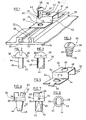
- Fig. 1 shows a portion of a cable duct profile made of extruded aluminum, other metallic materials are also possible.
- the profile area shown has a continuous grounding channel 20 which is accessible via a longitudinal slot 22 in the profile cross section.
- the clear inner profile of the grounding channel 20 has the shape of an inverted T, it is delimited by two L-profile-shaped strips (28) projecting in one piece from a base 24, which each form a slot surface (28) delimiting the longitudinal slot 22 at their free ends and open below this slot surface into a rectangular channel, the width of which is greater than the distance between the two slot surfaces 28, which is referred to below as the clear profile width and is approximately 4.2 mm in the exemplary embodiment shown.
- FIGS. 2 and 3 show an assembly picture
- a connector 30 made from a copper plate which has been bent twice and which has a bore 34 in a lower leg 32.
- the width of the connecting piece 30 corresponds to the outer width of the grounding channel 20, that is to say the outer spacing of its strips 26.
- a specially designed screw 36 can be inserted through the hole 34 above the hole 34.
- head 38 which is designed here as a round head, but the shape of which is not essential to the invention and can also take other forms, and a threaded shaft 40 with an M thread. It is flattened, in particular filed, on two opposite partial areas 42 of its lateral surface. The distance between these two mutually parallel, flat sections 42 is slightly smaller than the clear profile width of the longitudinal slot 42, so that the screw 36 in the position shown in FIG. 1 through the bore 34, which is wider than the largest shaft diameter, into the longitudinal slot 22 can be inserted.
- the screw 36 can be rotated back and forth somewhat without force, the angle of movement due to the undersize of the distance between the partial areas 42 (which is, for example, 4 mm) compared to the clear profile width (for example 4, 2 mm).
- the screw 36 can only be turned with considerable force.
- the diameter of their round thread jacket, which is only available in two parts, is significantly larger (e.g. 6 mm) than the clear profile width.
- the screw 36 Since the screw 36 was completely inserted into the longitudinal slot 22 in the described starting position before its rotation, in this position its screw head 38 rests on the leg 32 of the connection piece 30, the latter in turn rests on the top of the grounding channel 20, is at the same time with the Rotation of the screw 36, the screw head 38 has been pulled down, so the leg 32 has been pressed against the top of the grounding channel 20.
- the connector 30 has a plug-in lug, such as is used for plug-in connections in particular in the automotive sector, or a screw terminal, a knife contact strip, etc., as is known from electrical installation technology.
- connection piece 30 has an elevated central region 48, in which a bore 50 is provided.
- a square nut can be permanently fitted, for example fitted, under the central region 48; a neutral conductor, not shown, can then be pressed under the central region 48 by means of a screw. This can also have depressions for receiving the neutral or protective conductor.
- the axial length of the shaft 40 of the screw 36 is dimensioned so short that the screw 36 does not come into contact with the base 52 of the base 24 even in the tightened state described.
- the leg 32 can be somewhat resilient, so that it presses against the head 38 due to its elasticity when the screw 36 is tightened, thereby improving the electrical contact. Either a very short travel is chosen, the is smaller than the axial movement of the screw 36 with an approximately 90 degree rotation. Alternatively, a relatively large spring travel can also be selected, but then when tightening it must be ensured that the screw 36 is first pressed down against the elasticity of the leg 32 with a screwdriver before the twisting movement for the destruction of the anodized layer and the screwing in of one Thread takes place in the slot surfaces 28.
- An undercut profile for the grounding channel 20, as shown in FIG. 1, is basically not necessary, but is advantageous. Due to the undercut, the threads of the two thread areas 46 of the shaft 40 are pressed in at a precisely predetermined location, namely the slot surfaces 28 of the longitudinal slot 22. If, however, the grounding channel 20 is formed by two straight and without angling and parallel to each other, strips can be also carry out the invention, but the contact of the threaded areas 46 with the inner surfaces of such a slot takes place over a greater axial length of the screw 36, so that a higher force is necessary for the 90 degree rotation of the screw.
- the shaft 40 can be any non-circular cross-sections, for example oval, square or hexagonal cross-sectional shapes can be used.
- at least one edge 44 located at the front when tightened is formed on the shaft 40, which acts like a knife and cuts a thread profile into at least one slot surface 28.
- the exemplary embodiments discussed so far relate exclusively to the first alternative of the invention, namely a screw shaft 40 with a non-circular cross section, the cross section of which, however, remains unchanged over the entire axial length of the shaft 40.
- the second alternative is shown, here the shaft 40 of the screw 36 has a conical shape, it widens from a diameter at the lower end of the shaft 40 and into a slightly frustoconical extension 54 to a larger diameter immediately below of the head 38.
- the diameter at the lower end region, that is to say at the end piece 54 is somewhat smaller than the clear profile width.
- the shaft diameter in the area near the head is significantly larger than the clear profile width.
- the attachment 54 initially slides through the longitudinal slot 22 so far at the beginning of the assembly that the first threads can come into contact with the slot surfaces 28. Now begins the rotation of the screw 36, the threads increasingly cut into the slot surfaces 28, the screw is tightened until the leg 32 is sufficiently firmly pressed against the surface of the grounding channel 20.
- This embodiment thus has the advantage that the screw can be rotated as desired without the risk that it will assume a position which again corresponds to the starting position (FIG. 1). An inadvertent loosening of the screw 36 by too large an angle of rotation is therefore not possible. But it must be said that, for example, a 180 degree rotation of the screw according to the embodiment of FIG. 1 only has the disadvantage that you are back in the starting position and tightening the screw be - even with less effort - must be repeated.
- the diameter of the shaft 40 in the area close to the head must be matched to the thickness of the leg 32 and the parameters of the slot surfaces 28 in such a way that the screw on the one hand safely reaches the fastening position, that is to say that an inadmissibly high expenditure of force is not necessary to pull the leg 32 against the upper side to press the grounding channel 20, but on the other hand this effort is not impermissibly low because the thread could not cut sufficiently deep into the slot surfaces 28 when the head 38 presses the leg 32 against the grounding channel 20.
- the shaft 40 has a thread diameter at its lower, free end that is slightly smaller than the clear profile width and, based on this smaller diameter, a larger diameter is obtained in the area near the head, which sufficiently presses a thread into the slot surface 28 caused by turning the screw.
- the connecting piece 30 When tightening the screw 36, it may happen that the connecting piece 30 rotates as well.
- the connecting piece 30 according to FIG. 5 is designed such that it can engage with the tongue 56 in the longitudinal slot 22.
- a tongue 56 is provided on each end region, that is on the two legs 32. The tongue widens somewhat towards its connecting area with the leg 32, so that there is a largely play-free seat in the longitudinal slot 22.
- connection of the connecting piece 30 to the earthing channel 20, in particular its longitudinal slot 22 is possible, for example the legs 32 can be angled sideways downwards, as a result of which they rest on the outer walls of the strips 26.
- the formation of the connector 30 is largely free. The only important thing is that there is a fastening area similar to the leg 32 with which it can be pressed against the top of the grounding channel 20. The other training is arbitrary. So the connector 30 can also as electrical bridge between abutting sections of a cable duct are used, one leg 32 being in the area of one section and making an electrical connection there, while the other leg 32 is in the other section and causing the electrical contact there.
- the connector 30 is preferably made of a metal with good conductivity and good electrical surface properties, preferably copper or brass is used. This also applies to the screw 36.
- FIGS. 6 to 8 show one of many exemplary embodiments of a combination of the first and second alternatives of the solution according to the invention.
- the strut 36 shown in these figures has both a non-circular cross-section, as can be seen, for example, from FIG. 8, but its profile cross-section also widens starting from the profile cross-section at the lower end to the profile region close to the head.
- the screw 36 - similar to the screw 36 according to FIGS. 1 to 3 - has two opposing partial areas 42 of the casing which are flat. Starting from a cylindrical machine screw, opposing partial areas 42 running obliquely to the axis were filed away, resulting in the triangular partial areas 42 shown in FIG. 7. The areas of the shank that are not filed down, that is to say the threaded areas 46, have remained unprocessed and correspond to the design of the machine screw.
- this screw too can first be inserted into the longitudinal section 22 without any force being required for this.
- it cannot be pushed through, rather its diverging partial areas 42 come into contact with the slot surfaces 28 before the head lies on the grounding channel 20 Leg 32 comes to rest.
- This system is est achieved by rotating the screw 36.
- the shaft 40 has an edge 44 located at the front in the direction of rotation (like the exemplary embodiment according to FIGS. 1 to 3), by means of which a sharp cut into the slot surfaces 28 is possible.
- the fastening technique described by means of a non-round and / or tapered screw can also be used for other fastenings within the cable duct than for earthing lugs.
- Coax plugs or sockets the outer area of which must not be grounded, are attached using a strip made of an insulating material, which in turn is attached to the duct by means of at least one screw.
- the known methods for securing screw connections can be used, for example spring elements that are clamped together (spring washers according to DIN 127, spring washers according to DIN 137, spring lock washer according to DIN 6797, spring washer with protective jacket according to DIN 6913) or form-fitting elements (lock washers with outer nose, crown nuts, lock washers with rags according to DIN 93, DIN 463, lock washer with outer nose according to DIN 432 or with Inner nose according to DIN 462) can be used.
- a material bond has also proven to be favorable.
- a screw with microencapsulated adhesive is used in the area of its thread 46 and / or the smooth lower surface of its head 38.
- screw locks reference is made to Dubbel, Taschenbuch für den Maschinenbau, 14th edition, Springerverlag, pages 382, 383.
- Spring-head screws with a gear rim have also proven to be particularly cheap.
- Further securing devices result from the figures. 2 and 3, two projections 58, which are offset radially from the screw head 38 by 180 degrees and transversely as far as possible from the smooth lower surface of the head 38 (that is, in the vicinity) of the free end of the head 38).
- a U-shaped punching 64 can also be provided on the leg 62, as shown in broken lines in FIG. 5.
- a securing is effected in that after tightening the screw 36 with a screwdriver from above, the punching tongue 60, which is already bent slightly forward upon delivery to the end user, is engaged and this further into the plane of Leg 32 is bent until it rests in parallel on a surface of the non-circular, for example square screw head.
- a washer has also proven to be very advantageous for securing screws, which has a hole which is adapted to the shape of the screw shaft 46, so that it is inevitably rotated with the screw 36. It has a projection protruding from its plane, which is preferably resilient and engages when the screw is turned into the longitudinal slot 22 from above or below, as soon as the screw 36 has been turned 90 degrees and has thus reached the correct position. It is therefore not possible for the user to turn the screw 36 further (as in the exemplary embodiment according to FIGS. 1 to 3, dashed there), and the earth connection is also prevented from shaking free.
- the connecting piece is connected in one piece to the screw 36; it is formed by a partial area of the screw head 38.
- the screw head 38 is required longer than normal, it has a transverse bore 64 for receiving a bare protective conductor and a threaded bore 66 running transversely therein, into which screw can be screwed in for tightening and pressing the protective conductor.
Landscapes
- Connections By Means Of Piercing Elements, Nuts, Or Screws (AREA)
- Details Of Indoor Wiring (AREA)
- Waveguide Aerials (AREA)
Priority Applications (1)
| Application Number | Priority Date | Filing Date | Title |
|---|---|---|---|
| AT87710024T ATE88598T1 (de) | 1986-12-16 | 1987-12-15 | Kabelkanal mit mindestens einem aluminiumkanalprofil und einem anschlussstueck fuer einen schutzleiter. |
Applications Claiming Priority (2)
| Application Number | Priority Date | Filing Date | Title |
|---|---|---|---|
| DE3642896 | 1986-12-16 | ||
| DE3642896A DE3642896C2 (de) | 1986-12-16 | 1986-12-16 | Anschlußeinrichtung für Schutzleiter an Kabelkanälen mit mindestens einem Aluminium-Kanalprofil |
Publications (3)
| Publication Number | Publication Date |
|---|---|
| EP0272199A2 true EP0272199A2 (fr) | 1988-06-22 |
| EP0272199A3 EP0272199A3 (en) | 1990-02-07 |
| EP0272199B1 EP0272199B1 (fr) | 1993-04-21 |
Family
ID=6316280
Family Applications (1)
| Application Number | Title | Priority Date | Filing Date |
|---|---|---|---|
| EP87710024A Expired - Lifetime EP0272199B1 (fr) | 1986-12-16 | 1987-12-15 | Goulotte de câbles avec au moins un profilé de goulotte en aluminium et une pièce de raccordement pour un conducteur de protection |
Country Status (3)
| Country | Link |
|---|---|
| EP (1) | EP0272199B1 (fr) |
| AT (1) | ATE88598T1 (fr) |
| DE (2) | DE3642896C2 (fr) |
Cited By (5)
| Publication number | Priority date | Publication date | Assignee | Title |
|---|---|---|---|---|
| DE3941095C1 (en) * | 1989-12-13 | 1991-05-08 | Rieth & Co Gmbh, 7312 Kirchheim, De | Cable channel or tray support - has coupling element operable from above in form of self-tapping screw fitting selectable slots |
| GB2239990A (en) * | 1989-12-20 | 1991-07-17 | Cellux S A | Mounting earth connection on a wiring support |
| DE19949508A1 (de) * | 1999-10-14 | 2001-06-07 | Phoenix Contact Gmbh & Co | Vorrichtung zur Befestigung von Schirmklemmen |
| DE19817152C2 (de) * | 1997-04-18 | 2002-09-26 | Advantest Corp | Elektromagnetische Abschirmvorrichtung und Verfahren zum Abschirmen eines Kabelbündels |
| EP1291993A1 (fr) * | 2001-09-06 | 2003-03-12 | Aparellaje Electrico S.L. | Elément de canalisation métallique pour cablage électrique |
Families Citing this family (2)
| Publication number | Priority date | Publication date | Assignee | Title |
|---|---|---|---|---|
| DE10332214B4 (de) * | 2003-07-16 | 2009-10-15 | Popp Gmbh | Profilschiene sowie Verfahren zum Kontaktieren eines Leiters, insbesondere eines Erdungsleiters an einer Profilschiene |
| DE102011016544A1 (de) | 2011-04-08 | 2012-10-11 | Tehalit Gmbh | Verfahren und Leitungsführungskanal zur Sicherstellung eines Potentialausgleichs |
Family Cites Families (5)
| Publication number | Priority date | Publication date | Assignee | Title |
|---|---|---|---|---|
| US3752030A (en) * | 1971-07-29 | 1973-08-14 | F Steurer | Screw |
| US3842877A (en) * | 1972-06-05 | 1974-10-22 | A Andrews | Quick fastening screw device |
| DE7800248U1 (de) * | 1978-01-05 | 1978-04-13 | Bettermann Geb. Schlagheck, Ursula, 5064 Roesrath | Metallischer Installationskanal zum Anschluß einer Potentialausgleichleitung und Erdverbindung |
| DE3218523C2 (de) * | 1982-05-17 | 1985-12-19 | Anton 4100 Duisburg Kucera | Schlagschraube |
| GB2157095B (en) * | 1984-02-17 | 1988-02-17 | Cannon Davis Ass Ltd | Trunking system |
-
1986
- 1986-12-16 DE DE3642896A patent/DE3642896C2/de not_active Expired - Fee Related
-
1987
- 1987-12-15 DE DE8787710024T patent/DE3785560D1/de not_active Expired - Fee Related
- 1987-12-15 EP EP87710024A patent/EP0272199B1/fr not_active Expired - Lifetime
- 1987-12-15 AT AT87710024T patent/ATE88598T1/de active
Cited By (6)
| Publication number | Priority date | Publication date | Assignee | Title |
|---|---|---|---|---|
| DE3941095C1 (en) * | 1989-12-13 | 1991-05-08 | Rieth & Co Gmbh, 7312 Kirchheim, De | Cable channel or tray support - has coupling element operable from above in form of self-tapping screw fitting selectable slots |
| GB2239990A (en) * | 1989-12-20 | 1991-07-17 | Cellux S A | Mounting earth connection on a wiring support |
| DE19817152C2 (de) * | 1997-04-18 | 2002-09-26 | Advantest Corp | Elektromagnetische Abschirmvorrichtung und Verfahren zum Abschirmen eines Kabelbündels |
| DE19949508A1 (de) * | 1999-10-14 | 2001-06-07 | Phoenix Contact Gmbh & Co | Vorrichtung zur Befestigung von Schirmklemmen |
| DE19949508B4 (de) * | 1999-10-14 | 2007-09-20 | Phoenix Contact Gmbh & Co. Kg | Vorrichtung zur Befestigung von Schirmklemmen |
| EP1291993A1 (fr) * | 2001-09-06 | 2003-03-12 | Aparellaje Electrico S.L. | Elément de canalisation métallique pour cablage électrique |
Also Published As
| Publication number | Publication date |
|---|---|
| EP0272199A3 (en) | 1990-02-07 |
| DE3642896A1 (de) | 1988-06-30 |
| DE3785560D1 (de) | 1993-05-27 |
| DE3642896C2 (de) | 1994-01-27 |
| EP0272199B1 (fr) | 1993-04-21 |
| ATE88598T1 (de) | 1993-05-15 |
Similar Documents
| Publication | Publication Date | Title |
|---|---|---|
| EP3117112A1 (fr) | Système de fixation servant à monter des appareils, en particulier des appareils électriques | |
| DE102009019699B4 (de) | Anschlussklemme für Leiterplatten | |
| DE102014202951A1 (de) | Blitzschutzvorrichtung | |
| EP2034562B1 (fr) | Connecteur à fiches doté d'un corps d'isolation en une pièce | |
| DE2138715C3 (de) | Elektrische Klemmbuchse mit elastischer Klemmung | |
| EP0272199B1 (fr) | Goulotte de câbles avec au moins un profilé de goulotte en aluminium et une pièce de raccordement pour un conducteur de protection | |
| EP3262716A1 (fr) | Dispositif de contact pour la transmission d'énergie électrique à une plaque conductrice et procédé de montage d'un tel dispositif de contact | |
| EP1709711B1 (fr) | Dispositif de connexion d'un cable coaxial a un boitier | |
| EP2478592B1 (fr) | Mise en contact électrique d'un composant électrique | |
| DE19821747C1 (de) | Koaxialkabel-Anschlußeinrichtung insbesondere für Steckverbinder, Kabelverbinder und Gehäuse | |
| DE102016214444A1 (de) | Anschlusskrone und System zum Verbinden eines elektrischen Gerätes mit einem Anschlussmittel einer elektrischen Anlage | |
| EP3333982B1 (fr) | Adaptateur de raccordement permettant de raccorder un appareil électrique ainsi que système et installation électrique | |
| CH567338A5 (fr) | ||
| DE3909548C2 (fr) | ||
| DE4432542C2 (de) | Steckendverschluß | |
| DE19726055C1 (de) | Elektromagnetsystem und Verfahren zum Fügen von Kern und Joch in einem solchen System | |
| EP3267534A1 (fr) | Adaptateur de connexion destiné à raccorder un appareil électrique à un moyen de connexion d'une installation électrique et système correspondant et installation électrique | |
| EP1783868B1 (fr) | Broche de contact estampée et courbée | |
| WO2016198352A1 (fr) | Adaptateur de mise en contact électrique | |
| DE102014012910A1 (de) | Hochfrequenz-Steckverbindungseinrichtung, insbesondere Koaxial-Steckverbindungseinrichtung für Antennensteckdosen | |
| DE10228137B4 (de) | Fixiereinrichtung sowie Schraubverbinder für Kabelleiter mit einer derartigen Fixiereinrichtung | |
| EP3648273B1 (fr) | Unité d'installation électrique à griffes | |
| EP3249750A1 (fr) | Couronne de connexion et système de connexion d'un appareil électrique comprenant un moyen de connexion d'une installation électrique | |
| EP1753089A2 (fr) | Ensemble de connecteurs pour construire et séparer au moins une liaison électrique avec un autre ensemble de connecteurs complémentaires | |
| DE29822620U1 (de) | Kontaktanordnung, insbesondere für NH-Sicherungslasttrennschalter |
Legal Events
| Date | Code | Title | Description |
|---|---|---|---|
| PUAI | Public reference made under article 153(3) epc to a published international application that has entered the european phase |
Free format text: ORIGINAL CODE: 0009012 |
|
| AK | Designated contracting states |
Kind code of ref document: A2 Designated state(s): AT BE CH DE FR GB IT LI NL SE |
|
| PUAL | Search report despatched |
Free format text: ORIGINAL CODE: 0009013 |
|
| AK | Designated contracting states |
Kind code of ref document: A3 Designated state(s): AT BE CH DE FR GB IT LI NL SE |
|
| 17P | Request for examination filed |
Effective date: 19900703 |
|
| 17Q | First examination report despatched |
Effective date: 19920220 |
|
| GRAA | (expected) grant |
Free format text: ORIGINAL CODE: 0009210 |
|
| AK | Designated contracting states |
Kind code of ref document: B1 Designated state(s): AT BE CH DE FR GB IT LI NL SE |
|
| PG25 | Lapsed in a contracting state [announced via postgrant information from national office to epo] |
Ref country code: IT Free format text: LAPSE BECAUSE OF FAILURE TO SUBMIT A TRANSLATION OF THE DESCRIPTION OR TO PAY THE FEE WITHIN THE PRE;WARNING: LAPSES OF ITALIAN PATENTS WITH EFFECTIVE DATE BEFORE 2007 MAY HAVE OCCURRED AT ANY TIME BEFORE 2007. THE CORRECT EFFECTIVE DATE MAY BE DIFFERENT FROM THE ONE RECORDED.SCRIBED TIME-LIMIT Effective date: 19930421 Ref country code: NL Effective date: 19930421 Ref country code: SE Effective date: 19930421 Ref country code: FR Effective date: 19930421 Ref country code: GB Effective date: 19930421 |
|
| REF | Corresponds to: |
Ref document number: 88598 Country of ref document: AT Date of ref document: 19930515 Kind code of ref document: T |
|
| REF | Corresponds to: |
Ref document number: 3785560 Country of ref document: DE Date of ref document: 19930527 |
|
| EN | Fr: translation not filed | ||
| NLV1 | Nl: lapsed or annulled due to failure to fulfill the requirements of art. 29p and 29m of the patents act | ||
| GBV | Gb: ep patent (uk) treated as always having been void in accordance with gb section 77(7)/1977 [no translation filed] |
Effective date: 19930421 |
|
| PGFP | Annual fee paid to national office [announced via postgrant information from national office to epo] |
Ref country code: DE Payment date: 19931029 Year of fee payment: 7 |
|
| PGFP | Annual fee paid to national office [announced via postgrant information from national office to epo] |
Ref country code: BE Payment date: 19931103 Year of fee payment: 7 |
|
| PGFP | Annual fee paid to national office [announced via postgrant information from national office to epo] |
Ref country code: CH Payment date: 19931206 Year of fee payment: 7 |
|
| PGFP | Annual fee paid to national office [announced via postgrant information from national office to epo] |
Ref country code: AT Payment date: 19931229 Year of fee payment: 7 |
|
| PLBE | No opposition filed within time limit |
Free format text: ORIGINAL CODE: 0009261 |
|
| STAA | Information on the status of an ep patent application or granted ep patent |
Free format text: STATUS: NO OPPOSITION FILED WITHIN TIME LIMIT |
|
| 26N | No opposition filed | ||
| PG25 | Lapsed in a contracting state [announced via postgrant information from national office to epo] |
Ref country code: AT Effective date: 19941215 |
|
| PG25 | Lapsed in a contracting state [announced via postgrant information from national office to epo] |
Ref country code: BE Effective date: 19941231 Ref country code: LI Effective date: 19941231 Ref country code: CH Effective date: 19941231 |
|
| BERE | Be: lapsed |
Owner name: FIRMA MANFRED DAHL G.M.B.H. & CO. K.G. Effective date: 19941231 |
|
| REG | Reference to a national code |
Ref country code: CH Ref legal event code: PL |
|
| PG25 | Lapsed in a contracting state [announced via postgrant information from national office to epo] |
Ref country code: DE Effective date: 19950901 |