EP0272510A2 - Dispositif de diversité d'espace - Google Patents
Dispositif de diversité d'espace Download PDFInfo
- Publication number
- EP0272510A2 EP0272510A2 EP87117835A EP87117835A EP0272510A2 EP 0272510 A2 EP0272510 A2 EP 0272510A2 EP 87117835 A EP87117835 A EP 87117835A EP 87117835 A EP87117835 A EP 87117835A EP 0272510 A2 EP0272510 A2 EP 0272510A2
- Authority
- EP
- European Patent Office
- Prior art keywords
- phase shifter
- branches
- channel
- polarization
- receiving
- Prior art date
- Legal status (The legal status is an assumption and is not a legal conclusion. Google has not performed a legal analysis and makes no representation as to the accuracy of the status listed.)
- Ceased
Links
Images

Classifications
-
- H—ELECTRICITY
- H04—ELECTRIC COMMUNICATION TECHNIQUE
- H04B—TRANSMISSION
- H04B7/00—Radio transmission systems, i.e. using radiation field
- H04B7/02—Diversity systems; Multi-antenna system, i.e. transmission or reception using multiple antennas
- H04B7/10—Polarisation diversity; Directional diversity
-
- H—ELECTRICITY
- H04—ELECTRIC COMMUNICATION TECHNIQUE
- H04B—TRANSMISSION
- H04B7/00—Radio transmission systems, i.e. using radiation field
- H04B7/002—Reducing depolarization effects
Definitions
- the invention relates to a space diversity device in which the useful signals received by two antennas of the two reception branches are combined in a combiner in the BB or IF level.
- RF channels that operate on adjacent or on the same frequencies are decoupled in that the RF signals are transmitted on cross-polarized waves.
- the cross polarization decoupling (XPD) of the signals on a real radio field is, depending on the frequency and antenna type, in a fading-free time between approx. 20 and 35 dB.
- XPD cross polarization decoupling
- cross-polarization decoupling causes increased adjacent-channel or co-channel interference in the useful channel, which can result in increased bit error rates (BFQ) in digital radio relay systems or even in the failure of the system.
- BFQ bit error rates
- the cross polarization decoupling XPD is given in dB.
- the invention has for its object to provide a solution by which adjacent channel or co-channel interference in the useful channel can be reduced in a simple manner.
- This object is achieved according to the invention in such a way that, in the case of a space diversity receiver of the type described at the outset, the polarization directions of the antennas for the two reception branches are opposite to each other by an equal, small angle ⁇ in positive and negative directions compared to the individual setting aimed at maximum cross-polarization decoupling are rotated.
- curve 1 shows the cross-polarization decoupling XPD of an antenna as a function of the setting angle ⁇ .
- the curve runs through a maximum, which was assumed to be 32 dB here.
- the angle width and maximum can differ depending on the antenna type and frequency position.
- Curves 2 and 3 show the cross polarization decoupling XPD of two receiving antennas, whose direction of polarization deviates by + 4 ° and -4 ° from the optimal individual setting.
- XPD cross polarization decoupling
- the bit error rate BFQ must not exceed a predetermined value (eg 1 ⁇ 10 ⁇ 11).
- the plus-minus rotation of the antennas results in a broadening of the XPD curve, since only the better curve is effective in the combination of the signals according to the invention. If the direction of polarization is rotated by rain, one antenna first passes through its maximum of cross-polarization decoupling, while the other immediately assumes a smaller cross-polarization decoupling. If the room diversity device consists of two receivers and an advantageously bumpless changeover switch, which is controlled by the bit error rate or the error pulses of the two signals derived therefrom, only the receiver which has the lower bit error rate is switched to the output.
- Figure 2 shows a circuit with improvement of the XPD in the same and adjacent channel interference, each with a radio part Fu 1 and Fu 2 and a subsequent demodulator Dem 1 and Dem 2 receiver E1, E2 in the two reception branches, which have a BB combiner are merged.
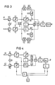
- FIG. 3 shows a room diversity receiver with an IF combiner and improvement of the XPD in the event of adjacent channel interference.
- the connection terminals for the antennas of the two reception paths are designated A1 and A2.
- the reception signal occurs in the RF position on them.
- Each receive branch contains a receive converter M1 or M2, which are fed from a common receive oscillator O, and a subsequent IF preamplifier V1 or V2.
- a receiving branch one is electronic Controlled phase shifter P arranged, in the other receiving branch a delay element T with the delay time ⁇ is switched on.
- the two reception branches are coupled into each via a branch circuit RK1 or RK2, at which signals from the reception branches are coupled out into a phase comparison circuit consisting of two measuring amplifiers MV1 and MV2, a phase comparator PV and a subsequent logic L connected to the phase shifter P. a summing circuit S merged.
- An IF main amplifier HV and a demodulator Dem are connected on the output side to the summing circuit S.
- the signals decoupled from the receiving branches via the branch circuits RK1 and RK2 are first fed to a measuring amplifier MV1 or MV2, the output signal of which is supplied to the phase comparison circuit already mentioned on the one hand and on the other hand to a series connection of a band-stop filter BS1 or BS2 and a rectifier G1 or G2 is given, which are connected to the two inputs of a differential amplifier D. This is connected on the output side to the ZF preamplifiers V1 and V2.
- the circuit described above acts in such a way that the measuring amplifiers MV1 and MV2 amplify the useful signal to a constant value which is corrected in the amplifier.
- the bandstopper BS1 and BS2 suppress the useful signal and let the rest of the neighboring signal pass, which is converted into a DC voltage value in the following rectifiers G1 and G2.
- the differential amplifier D determines the difference in the adjacent channel interference and controls the IF preamplifiers V1 and V2 in such a way that the path with the stronger adjacent channel noise is correspondingly reduced in the gain.
- the summer S the signals of both paths are added in phase. The more disturbed signal there has a correspondingly smaller amplitude than the weaker disturbed signal of the other path, so that in total an optimal signal-to-noise ratio is achieved.
- FIG. 4 shows an arrangement with which co-channel interference or adjacent channel interference caused by depolarization can be reduced together with the corresponding alignment of the antennas.
- the basic structure of the spatial diversity receiver with IF combiner corresponds to the spatial diversity receiver according to FIG. 3 in terms of the reception branches and the phase comparison circuit and the summing circuit combining the reception branches. The same elements are therefore provided with the same reference numerals.
- the different training consists in that instead of the bandstopper and rectifier in the return path of the signals decoupled from the receiving branches there is a control loop from the demodulator Dem via a control logic SL and a differential amplifier D to the IF preamplifiers V1 and V2.
- an LF generator G is provided, which is connected to an input of the control logic SL and the differential amplifier D and through which the amplification of the IF preamplifiers V1 and V2 are subjected to small fluctuations in opposite directions.
- the demodulator Dem measures the bit error rate BFQ and gives the data to the control logic SL. This now controls the gain of the IF preamplifiers V1 and V2 via the differential amplifier D so that the bit error rate reaches a minimum. Since the depolarization phenomena caused by rain are relatively slow processes, the control logic can be implemented with little effort.
Landscapes
- Engineering & Computer Science (AREA)
- Computer Networks & Wireless Communication (AREA)
- Signal Processing (AREA)
- Radio Transmission System (AREA)
- Radio Relay Systems (AREA)
Applications Claiming Priority (2)
| Application Number | Priority Date | Filing Date | Title |
|---|---|---|---|
| DE3643328 | 1986-12-18 | ||
| DE3643328 | 1986-12-18 |
Publications (2)
| Publication Number | Publication Date |
|---|---|
| EP0272510A2 true EP0272510A2 (fr) | 1988-06-29 |
| EP0272510A3 EP0272510A3 (fr) | 1989-11-02 |
Family
ID=6316527
Family Applications (1)
| Application Number | Title | Priority Date | Filing Date |
|---|---|---|---|
| EP87117835A Ceased EP0272510A3 (fr) | 1986-12-18 | 1987-12-02 | Dispositif de diversité d'espace |
Country Status (1)
| Country | Link |
|---|---|
| EP (1) | EP0272510A3 (fr) |
Cited By (7)
| Publication number | Priority date | Publication date | Assignee | Title |
|---|---|---|---|---|
| EP0766414A1 (fr) * | 1995-09-29 | 1997-04-02 | Telefonaktiebolaget Lm Ericsson | Station radio |
| RU2164726C2 (ru) * | 1999-02-23 | 2001-03-27 | Государственное унитарное предприятие Воронежский научно-исследовательский институт связи | Линия радиосвязи с повторным использованием частоты |
| RU2182401C1 (ru) * | 2001-01-03 | 2002-05-10 | Государственное унитарное предприятие Воронежский научно-исследовательский институт связи | Система радиосвязи с повторным использованием частоты |
| RU2188505C2 (ru) * | 2000-07-03 | 2002-08-27 | Государственное унитарное предприятие Воронежский научно-исследовательский институт связи | Система радиосвязи с повышенной имитостойкостью |
| RU2204208C2 (ru) * | 2000-09-19 | 2003-05-10 | Государственное унитарное предприятие Воронежский научно-исследовательский институт связи | Линия радиосвязи с многопараметрической модуляцией |
| RU2233030C2 (ru) * | 2002-07-01 | 2004-07-20 | Федеральное Государственное унитарное предприятие Воронежский научно-исследовательский институт связи | Радиолиния связи с повторным использованием частоты |
| RU2233029C1 (ru) * | 2003-01-21 | 2004-07-20 | Федеральное государственное унитарное предприятие "Воронежский научно-исследовательский институт связи" | Радиолиния связи с повторным использованием частоты |
Family Cites Families (1)
| Publication number | Priority date | Publication date | Assignee | Title |
|---|---|---|---|---|
| US3305781A (en) * | 1963-04-02 | 1967-02-21 | Raytheon Co | Diversity combiners |
-
1987
- 1987-12-02 EP EP87117835A patent/EP0272510A3/fr not_active Ceased
Cited By (8)
| Publication number | Priority date | Publication date | Assignee | Title |
|---|---|---|---|---|
| EP0766414A1 (fr) * | 1995-09-29 | 1997-04-02 | Telefonaktiebolaget Lm Ericsson | Station radio |
| US5963874A (en) * | 1995-09-29 | 1999-10-05 | Telefonaktiebolaget Lm Ericsson | Radio station arranged for space-diversity and polarization diversity reception |
| RU2164726C2 (ru) * | 1999-02-23 | 2001-03-27 | Государственное унитарное предприятие Воронежский научно-исследовательский институт связи | Линия радиосвязи с повторным использованием частоты |
| RU2188505C2 (ru) * | 2000-07-03 | 2002-08-27 | Государственное унитарное предприятие Воронежский научно-исследовательский институт связи | Система радиосвязи с повышенной имитостойкостью |
| RU2204208C2 (ru) * | 2000-09-19 | 2003-05-10 | Государственное унитарное предприятие Воронежский научно-исследовательский институт связи | Линия радиосвязи с многопараметрической модуляцией |
| RU2182401C1 (ru) * | 2001-01-03 | 2002-05-10 | Государственное унитарное предприятие Воронежский научно-исследовательский институт связи | Система радиосвязи с повторным использованием частоты |
| RU2233030C2 (ru) * | 2002-07-01 | 2004-07-20 | Федеральное Государственное унитарное предприятие Воронежский научно-исследовательский институт связи | Радиолиния связи с повторным использованием частоты |
| RU2233029C1 (ru) * | 2003-01-21 | 2004-07-20 | Федеральное государственное унитарное предприятие "Воронежский научно-исследовательский институт связи" | Радиолиния связи с повторным использованием частоты |
Also Published As
| Publication number | Publication date |
|---|---|
| EP0272510A3 (fr) | 1989-11-02 |
Similar Documents
| Publication | Publication Date | Title |
|---|---|---|
| DE2453435C2 (de) | Schaltungsanordnung zur Kompensation von Polarisationsverzerrungen in einem Funksystem | |
| DE69626250T2 (de) | Verfahren und Vorrichtung zur elektronischen Polarisationskorrektur | |
| DE69028840T2 (de) | Verwendung eines Polarisationswandlers für den Zugriff auf linearpolarisierte Satelliten mit einfach- oder dual zirkularpolarisierten Bodenstationsantennen | |
| DE3108029C2 (de) | FM-Empfänger für ein Kraftfahrzeug | |
| DE2608599A1 (de) | Schaltungsanordnung zur kompensation des durch kreuzpolarisation dual polarisierter wellen in einem mikrowellen-uebertragungssystem verursachten gegensprechens | |
| EP2031767A2 (fr) | Installation de diversité d'antennes dotée de deux antennes pour la réception radio dans des véhicules | |
| DE4229573A1 (de) | Funkempfaenger und -sender mit diversity | |
| DE3717841A1 (de) | Funkpeileinrichtung | |
| DE2252195A1 (de) | Diversity-empfaenger | |
| DE2009687A1 (fr) | ||
| DE1285576B (de) | Diversity-Empfangs-Verfahren | |
| EP0272510A2 (fr) | Dispositif de diversité d'espace | |
| DE69522126T2 (de) | Tuner für Satelliten-Rundfunkempfänger | |
| DE3612300C2 (fr) | ||
| DE2854128A1 (de) | Empfaengereingangsschaltung mit verbesserung des signal-rauschabstandes | |
| DE69227057T2 (de) | Signalstärkeanzeige eines Empfängers | |
| DE2505723A1 (de) | Einrichtung zur ueberwachung der von einer dvor-bodenstation abgestrahlten traegerfrequenz- und seitenbandsignale | |
| DE69215737T2 (de) | Radioempfangssysteme | |
| DE69519266T2 (de) | Mikrowellenmischerschaltung und diese Schaltung enthaltender Abwärtsumsetzer | |
| DE19925868B4 (de) | Diversity-TV-Empfangssystem | |
| DE1079702B (de) | Schaltung zur automatischen Entzerrung eines FM-UEbertragungssystems | |
| EP0086269A1 (fr) | Circuit de correction de la phase dans une installation de réception en diversity | |
| DE3223598C1 (en) | Adaptive reception antenna system - has compensation loop altering main antenna diagram using controlled weighting elements | |
| DE2643967C2 (de) | Empfangsseitige Einrichtung für eine mit Raumdiversity arbeitende Richtfunkstrecke | |
| DE69316272T2 (de) | Gleichfrequenzrundfunkübertragung eines einzigen Programms mittels einer Folge von Antennen mit orthogonaler Polarisation für zwei sich folgenden Antennen |
Legal Events
| Date | Code | Title | Description |
|---|---|---|---|
| PUAI | Public reference made under article 153(3) epc to a published international application that has entered the european phase |
Free format text: ORIGINAL CODE: 0009012 |
|
| AK | Designated contracting states |
Kind code of ref document: A2 Designated state(s): AT BE CH DE FR GB IT LI NL SE |
|
| PUAL | Search report despatched |
Free format text: ORIGINAL CODE: 0009013 |
|
| AK | Designated contracting states |
Kind code of ref document: A3 Designated state(s): AT BE CH DE FR GB IT LI NL SE |
|
| 17P | Request for examination filed |
Effective date: 19900410 |
|
| 17Q | First examination report despatched |
Effective date: 19920312 |
|
| STAA | Information on the status of an ep patent application or granted ep patent |
Free format text: STATUS: THE APPLICATION HAS BEEN REFUSED |
|
| 18R | Application refused |
Effective date: 19920827 |
|
| RIN1 | Information on inventor provided before grant (corrected) |
Inventor name: ULMER, WOLFGANG, DIPL.-ING. |