EP0272713A2 - Dispositif d'entraînement et de support pour deux systèmes à rotor tournant côte à côte et en sens inverse - Google Patents
Dispositif d'entraînement et de support pour deux systèmes à rotor tournant côte à côte et en sens inverse Download PDFInfo
- Publication number
- EP0272713A2 EP0272713A2 EP87202170A EP87202170A EP0272713A2 EP 0272713 A2 EP0272713 A2 EP 0272713A2 EP 87202170 A EP87202170 A EP 87202170A EP 87202170 A EP87202170 A EP 87202170A EP 0272713 A2 EP0272713 A2 EP 0272713A2
- Authority
- EP
- European Patent Office
- Prior art keywords
- drive
- bearing
- arrangement according
- bearing arrangement
- rotor
- Prior art date
- Legal status (The legal status is an assumption and is not a legal conclusion. Google has not performed a legal analysis and makes no representation as to the accuracy of the status listed.)
- Granted
Links
Images
Classifications
-
- B—PERFORMING OPERATIONS; TRANSPORTING
- B02—CRUSHING, PULVERISING, OR DISINTEGRATING; PREPARATORY TREATMENT OF GRAIN FOR MILLING
- B02C—CRUSHING, PULVERISING, OR DISINTEGRATING IN GENERAL; MILLING GRAIN
- B02C13/00—Disintegrating by mills having rotary beater elements ; Hammer mills
- B02C13/20—Disintegrating by mills having rotary beater elements ; Hammer mills with two or more co-operating rotors
- B02C13/205—Disintegrating by mills having rotary beater elements ; Hammer mills with two or more co-operating rotors arranged concentrically
-
- B—PERFORMING OPERATIONS; TRANSPORTING
- B02—CRUSHING, PULVERISING, OR DISINTEGRATING; PREPARATORY TREATMENT OF GRAIN FOR MILLING
- B02C—CRUSHING, PULVERISING, OR DISINTEGRATING IN GENERAL; MILLING GRAIN
- B02C13/00—Disintegrating by mills having rotary beater elements ; Hammer mills
- B02C13/26—Details
- B02C13/30—Driving mechanisms
-
- F—MECHANICAL ENGINEERING; LIGHTING; HEATING; WEAPONS; BLASTING
- F16—ENGINEERING ELEMENTS AND UNITS; GENERAL MEASURES FOR PRODUCING AND MAINTAINING EFFECTIVE FUNCTIONING OF MACHINES OR INSTALLATIONS; THERMAL INSULATION IN GENERAL
- F16C—SHAFTS; FLEXIBLE SHAFTS; ELEMENTS OR CRANKSHAFT MECHANISMS; ROTARY BODIES OTHER THAN GEARING ELEMENTS; BEARINGS
- F16C19/00—Bearings with rolling contact, for exclusively rotary movement
- F16C19/22—Bearings with rolling contact, for exclusively rotary movement with bearing rollers essentially of the same size in one or more circular rows, e.g. needle bearings
- F16C19/34—Bearings with rolling contact, for exclusively rotary movement with bearing rollers essentially of the same size in one or more circular rows, e.g. needle bearings for both radial and axial load
- F16C19/38—Bearings with rolling contact, for exclusively rotary movement with bearing rollers essentially of the same size in one or more circular rows, e.g. needle bearings for both radial and axial load with two or more rows of rollers
-
- F—MECHANICAL ENGINEERING; LIGHTING; HEATING; WEAPONS; BLASTING
- F16—ENGINEERING ELEMENTS AND UNITS; GENERAL MEASURES FOR PRODUCING AND MAINTAINING EFFECTIVE FUNCTIONING OF MACHINES OR INSTALLATIONS; THERMAL INSULATION IN GENERAL
- F16C—SHAFTS; FLEXIBLE SHAFTS; ELEMENTS OR CRANKSHAFT MECHANISMS; ROTARY BODIES OTHER THAN GEARING ELEMENTS; BEARINGS
- F16C23/00—Bearings for exclusively rotary movement adjustable for aligning or positioning
- F16C23/06—Ball or roller bearings
- F16C23/08—Ball or roller bearings self-adjusting
- F16C23/082—Ball or roller bearings self-adjusting by means of at least one substantially spherical surface
- F16C23/086—Ball or roller bearings self-adjusting by means of at least one substantially spherical surface forming a track for rolling elements
Definitions
- the invention relates to a drive and bearing arrangement for counter-rotating rotor systems of a disintegrator or the like.
- Disintegrators are used to shred various materials.
- disintegrators have rotor systems rotating in opposite directions with blade rings in a housing.
- the material to be shredded is entered inside the housing in the vicinity of the inner areas of the rotor systems and, as a result of the centrifugal scraping, is released to the outside, whereby it is shredded. Then it is carried out from the outer housing area.
- disintegrators of this type work like a device for crushing coal according to French patent specification 677 966.
- the rotor systems are attached to opposite ends of shaft ends which are mounted both in the housing and outside the housing.
- the shape of the rotor blades depends on which materials are to be crushed and for which speeds the disintegrators are designed.
- the rotor systems especially in the case of fast-running disintegrators, also act as gyroscopes, the generally uneven coatings of the blades with the comminuted material and their stress when adding not yet comminuted regrind cause four-fold so-called Alembert forces on the rotating Systems that mainly affect the bearings. If these bearings are part of the disinetrator housing, the latter acts as a soundboard for the radiation of the noise.
- the present invention is based on the object of creating a drive and bearing arrangement for the rotor systems of disintegrators, by means of which vibrations are reduced to a minimum and the formation of noise can be almost completely avoided.
- the vibration absorption according to the invention is carried out by construction elements which do not necessarily also have to derive the loads from drive belts.
- the rotor and drive bearings are special roller bearings that still work perfectly, especially at high speeds of around 3000 revolutions per minute.
- the drive and bearing arrangement according to the invention is neither part of the disintegrator housing, nor is it firmly connected to it, so that it cannot act as a resonance body for possibly incompletely compensated residual vibrations of the rotating systems.
- the vibration-absorbing elastic support of the support and supply pipe is carried out in a preferred embodiment, each by a special hydrodynamic bearing on the pipe ends, which is in a floating connection with the associated axle stub. These bearings can also work with smaller tolerances in order to achieve optimal damping of the vibrations that occur, depending on the size and speed of the disintegrator.
- the rotor and drive bearings are cooled by a coolant flow flowing through the carrier and supply pipe.
- Light oil can be used as a coolant. This enables the storage temperature to be reduced to 100 ° C to 120 ° C.
- the oil used for cooling, including hydraulic oil, also serves to dampen vibrations.
- the coolant flow within the drive and bearing assembly can be affected by keeping the drain opening slightly narrower than the inlet opening to cause a slight oil build-up.
- the drive and bearing arrangement By using the drive and bearing arrangement according to the invention, one is able not only to significantly increase the service life or lifespan of a disintegrator, but also to reduce the noise level to approximately 45 decibels. This value is measured approximately 10 m from the hall in which the disintegrator with the new drive and bearing arrangement is installed.
- the disintegrator need not be provided with a sound-absorbing, expensive housing.
- the use of sound locks in the disintegrator hall is also eliminated.
- the rotating systems are equipped with temperature sensors and vibration sensors, the lines of which are led through the support and supply pipe. They lead to a process computer, which, however, is not the subject of the present invention.
- the stub axles are anchored in bearings which consist of two bearing shells, of which the upper bearing shell can be raised relatively easily, so that the entire drive and bearing arrangement can be lifted off for replacement.
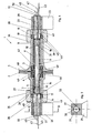
- Fig. 1 shows - partly schematically - a longitudinal section through the drive and bearing assembly 1 according to the invention.
- Two rotor carriers 2 and 3 rotating in opposite directions and side by side are only partially shown. Beyond the fault lines, rotor systems (not shown) can be attached to them with any blades. These rotor systems with the rotor blades and their design are not part of the present invention.
- Each rotor support 2 or 3 is mounted directly on a support and supply tube 6 by means of a rotor bearing 4 or 5, which will be explained in detail later.
- Each rotor bearing 4 or 5 is held by an unillustrated ring in the bearing bore in the rotor supports 2, 3, which is also not shown.
- Each rotor support 2, 3 is followed by a drive hub 9 or 14, the ends 10, 15 of which are each supported by means of a drive bearing 16 or 18 on an axially movable axle stub 26, 28 in a bearing block 20, 22.
- the rotor carriers 2 and 3 and their drive hubs 14 and 9 are made in one piece, for example from cast steel. Rotor carriers 2, 3 and drive hubs 14 and 9 each form a unit.
- the drive hubs 9 and 14 are of different lengths.
- the drive hub 9 shown on the right in FIG. 1 is longer than the left drive hub 14. This is because the feed hopper for the regrind is arranged on the right side of the drive and bearing arrangement 1 in the disintegrator housing, not shown.
- Each end 10, 15 of the drive hubs 9 and 14 is fixedly connected to a pulley 35, 36, via which the rotor systems are driven in opposite directions by means of flat belts from electric motors.
- the ends 10 and 15 of the drive hubs 9 and 14 are designed as cones 39 and 37.
- drive hubs 9 or 14 appropriately trained pulleys 35 and 36 are shrunk on.
- the pulleys 35 and 36 can also be connected in another way to the ends 10 and 15 of the drive hubs 9 and 14, respectively.
- the drive bearings 16 and 18 are arranged approximately in the middle of the pulleys 35 and 36, respectively.
- the respective outer race 17 and 19 of the drive bearings 16 and 18 abuts the end ring surfaces 38 and 40 of the conical ends 10 and 15 of the drive hubs 9 and 10.
- the rotor bearings 4 and 5 and the drive bearings 16 and 18 are designed as special spherical roller bearings, which also work safely at rotor speeds, for example at 3000 revolutions per minute.
- the drive bearings 16 and 18 are seated on stub axles 26 and 28, which are provided with longitudinal bores 27 and 29, respectively.
- the stub axles 26 and 28 are axially movably supported in the bearing blocks 20 and 22. Depending on the diameter of the drive hubs 9 and 14, this axial mobility can be permitted within the tolerances required to absorb the thermal expansion of the drive hubs 9 and 14.
- each bracket 20, 22 for anchoring the stub axles 26, 28 has a removable bearing shell 21 and 23, respectively, which can be easily lifted in a manner known per se. After lifting off, the entire drive and bearing arrangement 1 can easily be lifted out of its anchoring, which is very useful for the exchange and service.
- Each stub axle 26, 28 is opposite the bearing block 20, 22 by means of a nut key 52 ge secured against twisting.
- the vibration-damping elastic mounting of the support and supply pipe 6 takes place via novel hydrodynamic bearings 7 and 8, which are not the subject of the present invention. These hydrodynamic bearings 7, 8 are able to compensate for all substantially occurring vibrations of the systems rotating in opposite directions.
- the hydrodynamic bearings 7 and 8 are seated on journals 30 and 31 on the stub axles 26 and 28 and in bearing receiving bores 11 and 12 in the ends of the support and supply tube 6.
- the longitudinal bores 27 and 29 are through the journals 30 and 31 continued and aligned with the carrier and supply tube 6.
- the hydrodynamic bearings 7 and 8 permit a "floating" mounting of the rotor carriers 2, 3.
- temperature sensors 42 and vibration sensors 44 are arranged in the area of the rotor bearings 4 and 5 and drive bearings 16 and 18 designed as spherical roller bearings.
- Your lines 43 and 45 are through the support and supply tube 6 and the longitudinal bores 27 and 29 of the stub axles 26 and 28th led to the outside. They are connected to a process computer, not shown, which is not the subject of the present invention.
- Labyrinth seals 48 are arranged between the oppositely rotating rotor supports 2 and 3 and in front of the outer sides of the drive bearings 16, 18 designed as spherical roller bearings, which on the one hand prevent the ground material from penetrating into the area between the drive hubs 9 and 14 and the carrier and supply tube 6 and on the other hand protect the drive bearings. In this way, all spherical roller bearings 4 and 5 or 16 and 18 are secured against harmful effects.
- the labyrinth seals 48 are operatively connected to sealing gas nozzles 49, which are supplied via sealing gas lines 50. These sealing gas lines can either be routed outside or also within the carrier and supply pipe 6 and, as can be seen in FIGS.
- a supply connection 51 for a cooling liquid is indicated on the right-hand side of FIG. 1.
- the cooling liquid is introduced through the bores 27 and 29 into the interior of the carrier and supply pipe 6.
- the drive and bearing arrangement 1 is connected to a closed cooling circuit with an oil cooler, not shown.
- this cooling circuit is not shown in FIG. 1 shown.
- a particularly suitable hydraulic oil can be used as the cooling liquid.
- Fig. 2 shows that a groove key 52 ensures that the stub axles 26 and 28 are axially movable, but non-rotatably arranged in the bearing blocks 20 and 22.
- Both bearing blocks 20, 22 each have a removable bearing shell 21, 23, after removal of which the entire drive and bearing arrangement 1 can be lifted out of the bearing blocks 20 and 22 for replacement.
Landscapes
- Engineering & Computer Science (AREA)
- Food Science & Technology (AREA)
- Spinning Or Twisting Of Yarns (AREA)
- Support Of The Bearing (AREA)
- Rolls And Other Rotary Bodies (AREA)
- Rolling Contact Bearings (AREA)
- Crushing And Grinding (AREA)
- Crushing And Pulverization Processes (AREA)
- Filling Or Emptying Of Bunkers, Hoppers, And Tanks (AREA)
- Electrophotography Configuration And Component (AREA)
Priority Applications (1)
| Application Number | Priority Date | Filing Date | Title |
|---|---|---|---|
| AT87202170T ATE68725T1 (de) | 1986-12-24 | 1987-11-05 | Antriebs- und lageranordnung fuer zwei gegensinnig und nebeneinander umlaufende rotorsysteme. |
Applications Claiming Priority (2)
| Application Number | Priority Date | Filing Date | Title |
|---|---|---|---|
| DE3644448 | 1986-12-24 | ||
| DE3644448A DE3644448C1 (de) | 1986-12-24 | 1986-12-24 | Antriebs- und Lageranordnung fuer zwei gegensinnig und nebeneinander umlaufende Rotorsysteme |
Publications (3)
| Publication Number | Publication Date |
|---|---|
| EP0272713A2 true EP0272713A2 (fr) | 1988-06-29 |
| EP0272713A3 EP0272713A3 (en) | 1989-05-24 |
| EP0272713B1 EP0272713B1 (fr) | 1991-10-23 |
Family
ID=6317204
Family Applications (1)
| Application Number | Title | Priority Date | Filing Date |
|---|---|---|---|
| EP87202170A Expired - Lifetime EP0272713B1 (fr) | 1986-12-24 | 1987-11-05 | Dispositif d'entraînement et de support pour deux systèmes à rotor tournant côte à côte et en sens inverse |
Country Status (7)
| Country | Link |
|---|---|
| US (1) | US4891038A (fr) |
| EP (1) | EP0272713B1 (fr) |
| JP (1) | JP2544421B2 (fr) |
| AT (1) | ATE68725T1 (fr) |
| DE (1) | DE3644448C1 (fr) |
| ES (1) | ES2027285T3 (fr) |
| GR (1) | GR3003565T3 (fr) |
Cited By (1)
| Publication number | Priority date | Publication date | Assignee | Title |
|---|---|---|---|---|
| WO2011018581A1 (fr) * | 2009-08-11 | 2011-02-17 | Arnaud Becker | Broyeur ou concasseur a marteaux avec rotor en deux parties |
Families Citing this family (4)
| Publication number | Priority date | Publication date | Assignee | Title |
|---|---|---|---|---|
| FI119467B (fi) * | 2007-04-10 | 2008-11-28 | Fractivator Oy | Parannettu vastaiskumylly |
| CN103343779B (zh) * | 2013-07-22 | 2016-02-24 | 河南黎明重工科技股份有限公司 | 立轴冲击式破碎机传动轴承装置 |
| DE102014101786B4 (de) * | 2014-02-13 | 2016-12-22 | Hamburg Dresdner Maschinenfabriken Gmbh | Gegenläufige Stiftmühle |
| CN120906908B (zh) * | 2025-10-11 | 2025-12-09 | 爱安特(常州)精密机械有限公司 | 一种高强度轴承座 |
Family Cites Families (5)
| Publication number | Priority date | Publication date | Assignee | Title |
|---|---|---|---|---|
| DE152031C (fr) * | ||||
| DE351042C (de) * | 1920-10-19 | 1922-03-31 | Schlesinger & Co | Schleudermuehle mit einer oder mehreren umlaufenden Stiftenscheiben in wagerechter oder senkrechter Anordnung und beweglicher Haube |
| FR622053A (fr) * | 1926-01-29 | 1927-05-23 | Aux Forges De Vulcain | Tour à charioter à grand rendement et à grande vitesse |
| DE3034849A1 (de) * | 1980-09-16 | 1982-04-29 | Kasa-Forschungs- und Entwicklungs-Gesellschaft mbH & Co KG für Verfahrenstechnik, 6000 Frankfurt | Desintegrator und verfahren zum betrieb des desintegrators |
| DE3417556A1 (de) * | 1984-05-11 | 1985-11-21 | AGEFA Aktiengesellschaft für Aufbereitungstechnologie, Zunzgen | Desintegrator |
-
1986
- 1986-12-24 DE DE3644448A patent/DE3644448C1/de not_active Expired
-
1987
- 1987-11-05 AT AT87202170T patent/ATE68725T1/de not_active IP Right Cessation
- 1987-11-05 EP EP87202170A patent/EP0272713B1/fr not_active Expired - Lifetime
- 1987-11-05 ES ES198787202170T patent/ES2027285T3/es not_active Expired - Lifetime
- 1987-12-14 US US07/220,482 patent/US4891038A/en not_active Expired - Fee Related
- 1987-12-24 JP JP62325612A patent/JP2544421B2/ja not_active Expired - Lifetime
-
1992
- 1992-01-14 GR GR910401811T patent/GR3003565T3/el unknown
Cited By (2)
| Publication number | Priority date | Publication date | Assignee | Title |
|---|---|---|---|---|
| WO2011018581A1 (fr) * | 2009-08-11 | 2011-02-17 | Arnaud Becker | Broyeur ou concasseur a marteaux avec rotor en deux parties |
| FR2949079A1 (fr) * | 2009-08-11 | 2011-02-18 | Arnaud Becker | Broyeur ou concasseur a marteaux, ou analogues |
Also Published As
| Publication number | Publication date |
|---|---|
| GR3003565T3 (fr) | 1993-03-16 |
| ATE68725T1 (de) | 1991-11-15 |
| JPS63248455A (ja) | 1988-10-14 |
| JP2544421B2 (ja) | 1996-10-16 |
| US4891038A (en) | 1990-01-02 |
| ES2027285T3 (es) | 1992-06-01 |
| EP0272713A3 (en) | 1989-05-24 |
| EP0272713B1 (fr) | 1991-10-23 |
| DE3644448C1 (de) | 1988-06-01 |
Similar Documents
| Publication | Publication Date | Title |
|---|---|---|
| EP1194651B1 (fr) | Engin de construction et cylindre de fraisage | |
| DE2831458C2 (de) | Radantrieb für Arbeitsmaschinen, insbesondere für Kettenfahrzeuge | |
| DE3008949A1 (de) | Lager fuer eine mit hoher drehzahl umlaufende welle, insbesondere fuer rotorwelle eines turboladers | |
| EP0014695B1 (fr) | Tête de havage avec buses à eau et procédé de commande de cette tête | |
| DE8703410U1 (de) | Trockenzylinder od.dgl. einer Papier-, Karton- oder Streichmaschine | |
| DE4200687A1 (de) | Radiallager | |
| EP0272713B1 (fr) | Dispositif d'entraînement et de support pour deux systèmes à rotor tournant côte à côte et en sens inverse | |
| DE102004044911B4 (de) | Treibscheiben-Schachtfördermaschine mit verbesserter Kühlluftführung | |
| DE102020210331B4 (de) | Lagerhalter zum Aufnehmen eines Lagers | |
| DE2416229A1 (de) | Drehtrommel mit transmissionslosem antrieb | |
| EP1485218B1 (fr) | Traversee pour l'entree et le sortie d'eau de refroidissement d'un rouleau de transporteur loge au bout du rouleau | |
| DE2546723C2 (de) | Mehrfach gelagerte Strangführungsrolle | |
| EP1666671B1 (fr) | Fraise pour paroi moulée | |
| DE1400440A1 (de) | Lager fuer schnellaufende Wellen | |
| DE29908433U1 (de) | Walze | |
| DE1271583C2 (de) | Schraubenpropeller fuer schiffe | |
| CH621268A5 (fr) | ||
| EP0129038B1 (fr) | Dispositif de palier pour fonctionnement sous l'eau ou en milieux boueux | |
| DE102015008716A1 (de) | Antriebsanordnung für eine Schwenkbrücke | |
| EP0473908B1 (fr) | Marteau à foreuse et/ou à coup | |
| DE1942289A1 (de) | Trageuntergestell fuer dynamoelektrische Maschinen | |
| DE700016C (de) | Tellerbrecher | |
| DE9406702U1 (de) | Antriebsaggregat | |
| CH662066A5 (en) | Agitator mill | |
| DE939667C (de) | Gleitlager fuer elektromotorisch angetriebene Wellen von Maschinen zur Foerderung von Fluessigkeiten oder feuchten Gasen |
Legal Events
| Date | Code | Title | Description |
|---|---|---|---|
| PUAI | Public reference made under article 153(3) epc to a published international application that has entered the european phase |
Free format text: ORIGINAL CODE: 0009012 |
|
| AK | Designated contracting states |
Kind code of ref document: A2 Designated state(s): AT BE CH ES FR GB GR IT LI LU NL SE |
|
| PUAL | Search report despatched |
Free format text: ORIGINAL CODE: 0009013 |
|
| AK | Designated contracting states |
Kind code of ref document: A3 Designated state(s): AT BE CH ES FR GB GR IT LI LU NL SE |
|
| 17P | Request for examination filed |
Effective date: 19891121 |
|
| 17Q | First examination report despatched |
Effective date: 19900504 |
|
| RAP1 | Party data changed (applicant data changed or rights of an application transferred) |
Owner name: CITADEL INVESTMENTS LIMITED |
|
| GRAA | (expected) grant |
Free format text: ORIGINAL CODE: 0009210 |
|
| AK | Designated contracting states |
Kind code of ref document: B1 Designated state(s): AT BE CH ES FR GB GR IT LI LU NL SE |
|
| REF | Corresponds to: |
Ref document number: 68725 Country of ref document: AT Date of ref document: 19911115 Kind code of ref document: T |
|
| ITF | It: translation for a ep patent filed | ||
| ET | Fr: translation filed | ||
| GBT | Gb: translation of ep patent filed (gb section 77(6)(a)/1977) | ||
| REG | Reference to a national code |
Ref country code: ES Ref legal event code: FG2A Ref document number: 2027285 Country of ref document: ES Kind code of ref document: T3 |
|
| PLBE | No opposition filed within time limit |
Free format text: ORIGINAL CODE: 0009261 |
|
| STAA | Information on the status of an ep patent application or granted ep patent |
Free format text: STATUS: NO OPPOSITION FILED WITHIN TIME LIMIT |
|
| 26N | No opposition filed | ||
| REG | Reference to a national code |
Ref country code: GR Ref legal event code: FG4A Free format text: 3003565 |
|
| EPTA | Lu: last paid annual fee | ||
| EAL | Se: european patent in force in sweden |
Ref document number: 87202170.4 |
|
| PGFP | Annual fee paid to national office [announced via postgrant information from national office to epo] |
Ref country code: CH Payment date: 19961128 Year of fee payment: 10 |
|
| PGFP | Annual fee paid to national office [announced via postgrant information from national office to epo] |
Ref country code: GR Payment date: 19970227 Year of fee payment: 10 |
|
| PGFP | Annual fee paid to national office [announced via postgrant information from national office to epo] |
Ref country code: ES Payment date: 19970228 Year of fee payment: 10 |
|
| PGFP | Annual fee paid to national office [announced via postgrant information from national office to epo] |
Ref country code: GB Payment date: 19970304 Year of fee payment: 10 |
|
| PGFP | Annual fee paid to national office [announced via postgrant information from national office to epo] |
Ref country code: SE Payment date: 19970310 Year of fee payment: 10 |
|
| PGFP | Annual fee paid to national office [announced via postgrant information from national office to epo] |
Ref country code: BE Payment date: 19970313 Year of fee payment: 10 |
|
| PGFP | Annual fee paid to national office [announced via postgrant information from national office to epo] |
Ref country code: AT Payment date: 19970314 Year of fee payment: 10 |
|
| PGFP | Annual fee paid to national office [announced via postgrant information from national office to epo] |
Ref country code: NL Payment date: 19970320 Year of fee payment: 10 |
|
| PGFP | Annual fee paid to national office [announced via postgrant information from national office to epo] |
Ref country code: LU Payment date: 19970404 Year of fee payment: 10 |
|
| PG25 | Lapsed in a contracting state [announced via postgrant information from national office to epo] |
Ref country code: LU Free format text: LAPSE BECAUSE OF NON-PAYMENT OF DUE FEES Effective date: 19971105 Ref country code: GB Free format text: LAPSE BECAUSE OF NON-PAYMENT OF DUE FEES Effective date: 19971105 Ref country code: AT Free format text: LAPSE BECAUSE OF NON-PAYMENT OF DUE FEES Effective date: 19971105 |
|
| PG25 | Lapsed in a contracting state [announced via postgrant information from national office to epo] |
Ref country code: SE Free format text: LAPSE BECAUSE OF NON-PAYMENT OF DUE FEES Effective date: 19971106 Ref country code: ES Free format text: LAPSE BECAUSE OF THE APPLICANT RENOUNCES Effective date: 19971106 |
|
| PGFP | Annual fee paid to national office [announced via postgrant information from national office to epo] |
Ref country code: FR Payment date: 19971128 Year of fee payment: 11 |
|
| PG25 | Lapsed in a contracting state [announced via postgrant information from national office to epo] |
Ref country code: LI Free format text: LAPSE BECAUSE OF NON-PAYMENT OF DUE FEES Effective date: 19971130 Ref country code: GR Free format text: LAPSE BECAUSE OF NON-PAYMENT OF DUE FEES Effective date: 19971130 Ref country code: CH Free format text: LAPSE BECAUSE OF NON-PAYMENT OF DUE FEES Effective date: 19971130 Ref country code: BE Free format text: LAPSE BECAUSE OF NON-PAYMENT OF DUE FEES Effective date: 19971130 |
|
| BERE | Be: lapsed |
Owner name: CITADEL INVESTMENTS LTD Effective date: 19971130 |
|
| PG25 | Lapsed in a contracting state [announced via postgrant information from national office to epo] |
Ref country code: NL Free format text: LAPSE BECAUSE OF NON-PAYMENT OF DUE FEES Effective date: 19980601 |
|
| GBPC | Gb: european patent ceased through non-payment of renewal fee |
Effective date: 19971105 |
|
| REG | Reference to a national code |
Ref country code: CH Ref legal event code: PL |
|
| EUG | Se: european patent has lapsed |
Ref document number: 87202170.4 |
|
| NLV4 | Nl: lapsed or anulled due to non-payment of the annual fee |
Effective date: 19980601 |
|
| PG25 | Lapsed in a contracting state [announced via postgrant information from national office to epo] |
Ref country code: FR Free format text: LAPSE BECAUSE OF NON-PAYMENT OF DUE FEES Effective date: 19990730 |
|
| REG | Reference to a national code |
Ref country code: FR Ref legal event code: ST |
|
| REG | Reference to a national code |
Ref country code: ES Ref legal event code: FD2A Effective date: 20010402 |
|
| PG25 | Lapsed in a contracting state [announced via postgrant information from national office to epo] |
Ref country code: IT Free format text: LAPSE BECAUSE OF NON-PAYMENT OF DUE FEES;WARNING: LAPSES OF ITALIAN PATENTS WITH EFFECTIVE DATE BEFORE 2007 MAY HAVE OCCURRED AT ANY TIME BEFORE 2007. THE CORRECT EFFECTIVE DATE MAY BE DIFFERENT FROM THE ONE RECORDED. Effective date: 20051105 |