EP0272877A2 - Anzeigesystem für Fahrzeug - Google Patents
Anzeigesystem für Fahrzeug Download PDFInfo
- Publication number
- EP0272877A2 EP0272877A2 EP87311087A EP87311087A EP0272877A2 EP 0272877 A2 EP0272877 A2 EP 0272877A2 EP 87311087 A EP87311087 A EP 87311087A EP 87311087 A EP87311087 A EP 87311087A EP 0272877 A2 EP0272877 A2 EP 0272877A2
- Authority
- EP
- European Patent Office
- Prior art keywords
- display
- control
- master
- slave
- block
- Prior art date
- Legal status (The legal status is an assumption and is not a legal conclusion. Google has not performed a legal analysis and makes no representation as to the accuracy of the status listed.)
- Withdrawn
Links
Images


Classifications
-
- B—PERFORMING OPERATIONS; TRANSPORTING
- B60—VEHICLES IN GENERAL
- B60R—VEHICLES, VEHICLE FITTINGS, OR VEHICLE PARTS, NOT OTHERWISE PROVIDED FOR
- B60R16/00—Electric or fluid circuits specially adapted for vehicles and not otherwise provided for; Arrangement of elements of electric or fluid circuits specially adapted for vehicles and not otherwise provided for
- B60R16/02—Electric or fluid circuits specially adapted for vehicles and not otherwise provided for; Arrangement of elements of electric or fluid circuits specially adapted for vehicles and not otherwise provided for electric constitutive elements
- B60R16/023—Electric or fluid circuits specially adapted for vehicles and not otherwise provided for; Arrangement of elements of electric or fluid circuits specially adapted for vehicles and not otherwise provided for electric constitutive elements for transmission of signals between vehicle parts or subsystems
-
- B—PERFORMING OPERATIONS; TRANSPORTING
- B60—VEHICLES IN GENERAL
- B60H—ARRANGEMENTS OF HEATING, COOLING, VENTILATING OR OTHER AIR-TREATING DEVICES SPECIALLY ADAPTED FOR PASSENGER OR GOODS SPACES OF VEHICLES
- B60H1/00—Heating, cooling or ventilating devices
- B60H1/00642—Control systems or circuits; Control members or indication devices for heating, cooling or ventilating devices
- B60H1/00985—Control systems or circuits characterised by display or indicating devices, e.g. voice simulators
-
- G—PHYSICS
- G06—COMPUTING OR CALCULATING; COUNTING
- G06F—ELECTRIC DIGITAL DATA PROCESSING
- G06F3/00—Input arrangements for transferring data to be processed into a form capable of being handled by the computer; Output arrangements for transferring data from processing unit to output unit, e.g. interface arrangements
- G06F3/01—Input arrangements or combined input and output arrangements for interaction between user and computer
- G06F3/03—Arrangements for converting the position or the displacement of a member into a coded form
- G06F3/033—Pointing devices displaced or positioned by the user, e.g. mice, trackballs, pens or joysticks; Accessories therefor
-
- G—PHYSICS
- G06—COMPUTING OR CALCULATING; COUNTING
- G06F—ELECTRIC DIGITAL DATA PROCESSING
- G06F3/00—Input arrangements for transferring data to be processed into a form capable of being handled by the computer; Output arrangements for transferring data from processing unit to output unit, e.g. interface arrangements
- G06F3/14—Digital output to display device ; Cooperation and interconnection of the display device with other functional units
-
- G—PHYSICS
- G05—CONTROLLING; REGULATING
- G05B—CONTROL OR REGULATING SYSTEMS IN GENERAL; FUNCTIONAL ELEMENTS OF SUCH SYSTEMS; MONITORING OR TESTING ARRANGEMENTS FOR SUCH SYSTEMS OR ELEMENTS
- G05B2219/00—Program-control systems
- G05B2219/20—Pc systems
- G05B2219/23—Pc programming
- G05B2219/23121—Display graphics with corresponding text
Definitions
- This invention relates to display systems for use in vehicles, particularly automotive vehicles.
- vehicles particularly automotive vehicles.
- microprocessors for the efficient control of the automobile engine was the first practical example of this technology. More recently, microprocessors have been placed in radios, climate control systems, instrument panels, etc. The following references describe a variety of known systems of interest.
- References 1, 3, 4, 5, 7, 8 and 10, for example, describe the use of microprocessors in automotive vehicles.
- Reference 2 illustrates pictographic symbols (icons) for use in automotive applications.
- Reference 6 discusses the use of touch sensitive displays.
- Reference 9 describes the 1984 Buick Questor while References 11, 12 and 13 describe the 1986 Buick Riviera Graphic Control Centre.
- the object of the present invention is to provide an improved display system for a vehicle, in particular an automotive vehicle.
- the invention relates to a display system for a vehicle of the type comprising a display unit for displaying graphics and text to an operator of the vehicle, touch switch entry means for entry of desired function information by the operator and generation of touch input signals, discrete switch entry means for entry of additional function information by the operator and generation of discrete signals, and a display controller for controlling the display system operations by selective partitioning of system functions.
- the display system is characterised in that the display controller comprises an input/output (I/O) channel, an interprocessor data link for transferring data and commands between data processors, a master microprocessor for issuing control signals and responding to control signals representative of selected system functions, storage means associated with the master microprocessor for storing master data and commands and a master control program to control master functions in the system, the master functions including control of graphics and text for display on the display unit in response to the touch switch means and the discrete switch means, and a slave microprocessor for issuing and responding to control and data signals involving communication with the master microprocessor via the input/output channel and the interprocessor data link, and storage means associated with the slave microprocessor for storing slave data and commands and a slave control program to control slave functions in the system, the slave functions including control and monitoring of communications internally within the display controller and externally by the display controller.
- I/O input/output
- interprocessor data link for transferring data and commands between data processors
- a master microprocessor for issuing control
- a display system provides flexibility of function, environmental compatibility, and high reliability.
- the system provides most functions which are normally provided by way of discrete switches, knobs and visual indicators on the dashboard of the vehicle. This is done by simulating the buttons, knobs, and indicators with graphical and textual information shown on a display screen. In addition, other useful functions are provided which are not normally available.
- the display system is designed to serve as a centralised control point for most vehicle comfort, entertainment, and information display functions.
- microprocessor based display system of this type also facilitates advanced functions such as sophisticated trip computer functions, appointment calendar, mobile phone directory with automatic dialling, calculator, and electronic compass display, to name a few.
- advanced functions such as sophisticated trip computer functions, appointment calendar, mobile phone directory with automatic dialling, calculator, and electronic compass display, to name a few.
- the design of such a display system allows the display characteristics and supported functions to be changed through reconfigurable hardware and software, allowing a broad range of applications in different model automobiles.
- the display system has electronic circuitry to allow it to be programmed to display monochrome or colour graphics and text on an all-points-addressable display device such as a Cathode Ray Tube (CRT) or an Electro-Luminescent (EL) Flat Panel.
- CRT Cathode Ray Tube
- EL Electro-Luminescent
- the display resolution and scan rates may be programmed differently depending on the display type and size.
- the vehicle operator may control the display system via a reconfigurable switch system (RSS), such as an Infrared Touch Panel or Mylar (Registered Trade Mark) Touch Switch Matrix mounted over the face of the display device.
- RSS reconfigurable switch system
- Infrared Touch Panel or Mylar (Registered Trade Mark) Touch Switch Matrix mounted over the face of the display device.
- external discrete switches may also be attached to the display system.
- the display system preferably includes a master microprocessor and a slave microprocessor and communicates with other parts of the vehicle via two serial data communication links, a Random Access bus and a Poll/Response bus.
- serial data links and microprocessor based control modules greatly reduces the complexity of the vehicle wiring harness and serves to increase the overall reliability and serviceability of the vehicle.
- the display system preferably uses mostly low power CMOS electronic components which can serve to reduce the power dissipation and increase the reliability of the display system.
- Fig. 1 is a block diagram of the vehicle display system and other vehicle systems or elements.
- the vehicle display system comprises an Entertainment systems block 10, climate Control systems block 11, Vehicle Display system block 12, Instrument Panel block 13, Body Control system block 14 and Engine Control systems block 15.
- Blocks 10, 11 and 12 are interconnected by way of Random Access bus 16 while blocks 12, 13, 14, and 15 are interconnected by way of a Poll/Response bus 17. Inputs are supplied from automobile status switches by way of bus 18 to block 12.
- Entertainment systems block 10 controls the entertainment functions of the vehicle such as the AM/FM stereo radio, cassette player, cellular telephone and compact disk player.
- the climate Control systems block 11 controls the heating, ventilation and air conditioning system of the vehicle.
- Instrument Panel block 13 controls the display of functions such as the speedometer, engine oil and other associated engine functions.
- Body Control systems block 14 controls vehicle data such as time of day clock, trip odometer and trip computer functions.
- Engine Control systems block 15 controls the operation of the engine and provides information for display on the Instrument Panel block 13 as well as information to the Body Control systems block 14 for use in trip computer calculations.
- the Vehicle Display system block 12 accepts information via the Poll/Response bus 17 from the Body Control systems block 14 and the Engine Control systems block 15 for display to the vehicle operator.
- the Vehicle Display system block 12 accepts inputs from the vehicle operator in the form of switch sense and touch sense inputs from automobile status switches bus 18. The Vehicle Display system block 12 also generates commands across the Random Access bus 16 to the climate Control systems block 11 and Entertainment systems block 10 based on the input from the vehicle operator.
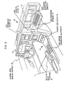
- Fig. 2 shows the interior of an automobile with several options.
- the automobile interior which is representative of most automobiles, includes a dashboard 30 and console 31 and shows optional features such as a CRT information centre Display Unit 36, data processing display and computer 32, data processing keyboard 33, compact disk player 40, push button transmission selector 37, cellular radio telephone 41, and steering wheel mounted controls 35.
- the vehicle also has an instrument panel 13.
- a standard vehicle display system would include the CRT information centre 36, and an expanded vehicle display system would include the data processing display and computer 32 as well as the data processing keyboard 33.
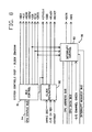
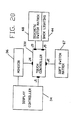
- Fig. 3 illustrates a Display controller and Display unit in conjunction with the other systems and components of the vehicle.
- Fig. 3 shows the Display controller 34, Display unit 36, a climate Control systems block 11, radio 45, compact disk player 40, cassette player 42, and optional cellular radio phone 41, which are interconnected by way of Random Access bus 16, and Engine Control systems 15, Body Control systems 14, Anti Skid Brake system 47, Adjustable Shock Absorbers 48, instrument panel 13 and compass 46, which are interconnected by way of Poll/Response bus 17.
- Input signals are used to control the power and operating mode of the Display controller. Interface signals to external sensors and the touch panel are also provided. Additional details are shown in Fig. 4.
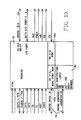
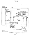
- Fig. 4 illustrates the Display controller 34, the Display block 36a, the Touch controller block 36b and Switch assemblies 36c. Also shown are various interconnecting signal lines between the Display controller, the Touch controller and the Display unit. Signals of interest are input signals for power moding control for example Not DCS On, IGN1 and IGN2. The Not DCS On input controls the power on and power off sequencing of the vehicle display system. The IGN1 and IGN2 signals control the moding of the system, such as run, crank (start) and accessory modes. Other signals of interest are the Not Monitor On line between the Display controller 34 and Display 36a as well as the Video signal, Horizontal sync signal, and Vertical sync signal.
- Signals of interest are input signals for power moding control for example Not DCS On, IGN1 and IGN2.
- the Not DCS On input controls the power on and power off sequencing of the vehicle display system.
- the IGN1 and IGN2 signals control the moding of the system, such as run, crank (start) and accessory modes.
- Other signals of interest are the Not
- Signals of interest between the Display controller 34 and Touch controller 36b are the SDL, Serial Data Link signal and TCON, Touch Controller On signal. These signals control the Touch controller power on and off and the reporting of Touch inputs from the vehicle operator through the Touch controller to the Display controller 34 via the Serial Data Link, SDL.
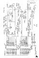
- Figs. 5A and 5B illustrate two versions of the Display controller and include similar elements with several exceptions.
- the Display controller includes an 80C88 microprocessor system 50, EEROM 51, RAM 52, and power supply circuitry 53. It also includes a watchdog timer 55, ROM 56, and 82C55 Interprocessor Data Link 57. Connected to the data link 57 by way of bus 71 is an 80C31 system block 60, ROM 61, RAM 62, and data links 63 which communicate with other devices via bus 19. Connected to blocks 50-52 and 55-57 by way of bus 70 are the Video circuitry block 65 with associated bus 73 and Video memory 66 as well as a Touch Switch circuitry block 67, associated Touch Switch matrix bus 74 and a Discrete Input circuitry block 68 with a status switch bus 75.
- FIG. 5B In Fig. 5B, most of the elements shown in Fig. 5A are repeated with the exception that the Interprocessor Data Link block 57 in Fig. 5A is replaced with a RAM Arbitration logic block 80.
- the various blocks in Figs. 5A and 5B including the Interprocessor Data Link block 57 and RAM Arbitration logic block 80 are described in detail later.
- Figs. 6A and 6B show two similar block diagrams of the Display controller.
- Fig. 6A shows a standard Display controller and
- Fig. 6B shows an expanded Display controller.
- Fig. 6A Shown in Fig. 6A is the 80C88 processor (master microprocessor) 50, systems controls chip 90, and EPROM 56A, which is similar to block 56 shown in Figs. 5A and 5B. Also shown is Touch Reconfigurable Switch System (RSS), miscellaneous I/O block 69, static RAM block 52, and EEPROM block 51a, similar to block 51 in Figs. 5A and 5B. Also shown is Video Display controller block 65a and output bus 73, and display buffer 66a attached to video Display controller 65a. The 80C31 serial communication processor (slave microprocessor) block 60 is attached to the Poll/Response bus 17 and Random Access bus 16. Also shown is power supply subsystem block 53 and I/O channel bus 70.
- RSS Touch Reconfigurable Switch System
- miscellaneous I/O block 69 miscellaneous I/O block 69
- static RAM block 52 static RAM block 52
- EEPROM block 51a similar to block 51 in Figs. 5A and 5B
- Fig. 6B shows an expanded Display controller with additional function. Added are ROM, Basic Input/Output System (BIOS) block 56a, System DRAM block 52a, DMA controller block 100, keyboard block 101, Diskette controller block 102, Diskette Drive block 103, RS232 interface block 104 and Mobile Telephone and Modem block 105.
- BIOS Basic Input/Output System
- the expanded Display controller allows additional functions such as On-vehicle data processing and data communication with remote data bases.
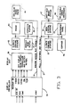
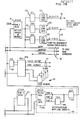
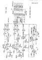
- Fig. 7 is a more detailed diagram of the Display controller.
- the controller design makes use of two microprocessors: an 80C88 (8088) microprocessor 50 serves as the master microprocessor and an 80C31 (8031) microprocessor 60 serves as a slave communications microprocessor.
- Each microprocessor has its own address latching and decode circuitry, comprising blocks 131, 132 and 133 for the 8088 microprocessor and blocks 140 and 141 for the 8031 microprocessor.
- Other elements include blocks 135 and 136 for the 8088 decode circuitry.
- the System Bus controller 90 is a CMOS logic device which serves as the system clock generator, bus controller, and interrupt controller. It produces the standard 8088 bus control signals based on the S0, S1, S2 signals from the 8088. It also handles external interrupt requests and generates the 8088 clock signal.
- the System Bus controller also has provisions for attachment of an external keyboard.
- VGA 65a Another CMOS logic device, the Video Gate Array (VGA) 65a, is controlled by the 8088 to provide the display of graphics and text on the attached display device.
- the VGA is a general purpose video controller which may be configured via software to support various types of all-points-addressable display devices with variable resolutions and scan rates.
- the VGA controls either 64K or 256K bytes of video memory 66 which is directly addressable by the 8088.
- the video memory is configured as four bit planes, each containing 16K or 64K bytes of RAM depending on the maximum desired resolution.
- the six outputs generated by the VGA 65a are used to supply the picture and synchronisation signals to the display device.
- the 8088 and 8031 microprocessors have their own independent memory address spaces.
- the 8088 control program is stored in the Read Only Memory (ROM) device 56.
- the 8088 also has a low power RAM Memory 52 which is always kept active by the vehicle's battery. Information which is to be retained when the vehicle is not in use, such as radio status, climate system setting, and trip monitor status are kept in this memory. A checksum algorithm is used to verify the validity of the data in the RAM. If the battery is disconnected, the contents of the RAM will be lost. At the next power on time the RAM will be initialised to the system default values. The parts of the RAM not used for this type of information are used as workspace for the control program stored in ROM.
- a non-volatile storage device EEPROM 51 is also provided to allow the 8088 to permanently store critical information such as the phone directory data, appointment calendar information, and service log information. This information is not lost if the battery is disconnected.
- the 8031 is provided with a ROM 61 for control program storage as well as a RAM 62 for communication buffer space and control program workspace. Communication between the 8088 and the 8031 is provided by the Interprocessor Data Link 57 composed of 82C55 (8255) programmable peripheral interface 145 and the associated bus driver circuits 146 and 147.
- the discrete inputs and outputs 18 and 74 are used by the 8088 to receive touch switch information, determine the proper operating mode, and control the power to the attached display device.
- the Universal Asynchronous Receiver/Transmitter (UART) included in the 8031 microprocessor is programmed to perform as a slave device on the Poll/Response bus 17. Through this bus the Display controller monitors and controls the operation of devices such as the Engine Control system, Body Control system, Instrument Panel, etc.
- the Random Access bus is also connected to the 8031. This link operates at 1K BAUD and is a contention bus.
- the 8031 uses one of its external interrupt inputs to detect the start of a bit on the Random Access bus and to provide a link sampling input to the 8031.
- the 8031 uses one of its internal timers to guarantee the sampling of each received data bit at the proper time. Transmission of data on the Random Access bus 17 is controlled and monitored by the 8031 via its control program and the 8031 integrated input/output ports.
- the display controller architecture reduces the number of different Programmable Read Only Memories (PROM's) required for a multi-microprocessor system.
- the Display controller has two microprocessors, one to control system operations, standard I/O and Display controls, the second to control two serial communication links that interface with other subsystems.
- the second microprocessor in this controller heretofore has had two PROM's (or ROM's) to define its operation. It is desirable that controllers be used for different car model applications, but each application would require two unique PROM's to personalise performance.
- the architecture herein described reduces personalisation to a single PROM. In the protocol architecture between the master and the slave microprocessors only one ROM 56 contains the personality of the vehicle platform. The ROM 61 for the slave microprocessor becomes generic regardless of changes to the command/ response structure of the specific bus.
- Fig. 8 is a block diagram of the System Controls chip. Internal elements include the Bus Control block 91, clock generation block 92, Interrupt Control block 93, and a CPU status bus 94. A variety of command, address and data signal lines is shown. Bus control block 91 accepts inputs from the 8088 CPU Status Bus 94 which determines the activation of the control signal outputs to the system bus. Clock generation block 92 generates the system bus Clock, Reset, and Memory ready signals based on the 14 MHz oscillator, I/O Channel Ready, and System Reset inputs.
- Interrupt Control block 93 generates the 8088 CPU Interrupt Request Signals INTR and NMI based upon the Interrupt Request bus inputs, I/O Channel Check input, and the state of the internal interrupt enable and priority registors.
- the interrrupt enable and priority registers are set via the CPU address and data bus inputs to the Interrupt Control block 93.
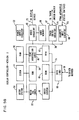
- Fig. 9 is a block diagram showing the internal connections of the Video Gate Array (VGA) chip 65a.
- Internal blocks include Address Multiplexer block 150, CRT control block 151, Graphic control 1 block 152, Graphic control 2 block 153, Sequence control block 154, and Attribute control block 155.
- Other blocks include the four display buffer bit planes 0, 1, 2 and 3 shown as blocks 156, 157, 158, and 159 respectively.
- Inputs to the VGA chip are by way of the I/O channel 70 and outputs to the display device are via the video output 73.
- the Address Multiplexer block 150 serves to select the source of the address signals which drive the display buffer bit planes. During normal display refresh, the address generated by the CRT control block 151 is selected by the Address Multiplexer block 150 to be the control display buffer address. When the display buffer information (picture) is being changed by the 8088 CPU, the Address Multiplexer block 150 selects the CPU provided address from the I/O Channel 70 to drive the display buffer planes.
- the CRT control block 151 controls the display refresh and synchronisation signal generation.
- the Sequence control block 150 controls the display buffer access and video signal timings.
- Graphic control blocks 152 and 153 control the mapping of the display buffer data into actual picture elements (PIXELS). This mapping is dependent upon control register values which may be changed via I/O Channel 170.
- Attribute control block 155 controls the display attributes such as blinking, underline, and high/low intensity when character display modes are selected.
- Fig. 10 is a diagram of the integrated RAM arbitration logic used in conjunction with the 8031 microprocessor as shown in Fig. 5B, version 2 of the Display controller, except that in Fig. 10 the 8031 microprocessor has been replaced with an 80C32 microprocessor which has one added hardware timer.
- Integrated onto the single chip is a 2K dual port RAM block 62a, 8K ROM block 61a and the RAM arbitration logic block 80.
- This implementation of the Display controller allows commands and data to be passed between the 80C88 and 8031 processors more rapidly than that of version 1 which uses the 80C55 as an interprocessor data link.
- the RAM Arbitration logic allows both the 8032 and 8088 processors to share the 2K RAM block 62A.
- the RAM Arbitration logic block 80 handles Requests from both the 8032 and 8088 CPUs for shared data and determines which CPU is allowed to access the RAM. If Requests for access occur simultaneously from both CPUs, the 8032 is given priority and the 8088 access is delayed by bringing the 8088 Memory Ready control signal low until the 8032 access is completed. Without the RAM arbitration logic block 80, all data which is to be shared by the two processors must be passed under direct program control via an interprocessor data link which requires complete cooperation of both processors.
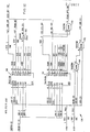
- Figs. 11A and 11B show further detail of blocks 120-125 in Fig. 7.
- the driver circuit blocks 165-167 for the output signals SDL, TCON, and Monitor ON are shown as well as the input wrapback receiver blocks 170-172 on Fig. 11A.
- Fig. 11B shows input receiver circuits 175-177 for the IGN1, IGN2, and DCS ON signals. Also shown is the crank (start) detection logic blocks 178-180. Miscellaneous resistors, capacitors, and diodes serve as signal conditioning and transient protection components.
- Fig. 11A circuit operation assume it is desired to bring the TCON output low and the Monitor ON and SDL outputs high.
- the control program first sets the bit in register AL which corresponds to the SDL control bit (bit 0) and TCON output (bit 1) to a logic one and resets the Monitor ON control bit (bit 2) to a zero.
- This value of register AL is then sent to the Output Port latch block 120 via an OUT instruction and activates the latch block 120 gate input to force the latch to retain the output data value. This new data forces the TCON transistor driver 166 to turn on thus pulling the TCON output low through resistor R46.
- transistor driver 167 is turned off and the Monitor ON output is pulled to 12 volts through resistor R39 since the SDL driver block 165 would be floating due to the input being at a higher voltage than the reference voltage of 2.5 volts created by voltage divider resistors R42 and R44.
- the current state of the SDL, TCON, and Monitor ON signals may be read at any time by the 8088 CPU via receiver circuits 170-172 and Input Port block 121.
- Fig. 11B operates in a manner similar to that of the input circuits of Fig. 11A but for the IGN1, IGN2, and DCS ON signals.
- Receivers 175-177 serve to convert the 12 volt signals to 5 volt logic levels and pass them to the input port block 122 where they may be sampled by the 8088 CPU.
- Logic circuits 178-180 serve to detect the presence of a vehicle cranking condition and to produce a CRANK signal which will alert the 8088 CPU of the condition via an interrupt.
- the 8088 CPU must perform a sequenced shutdown procedure to save critical data in the Keep Alive RAM prior to the activation of the vehicle starter motor. A valid crank condition is detected by the logic when the IGN1 input is high, the IGN2 input is low, and the DCS ON input is high.
- Fig. 12 shows additional details of miscellaneous decode logic shown as block 136 of Fig. 7.
- Blocks in Fig. 12 include two decoder circuit blocks 190 and 191 as well as miscellaneous blocks 192-195.
- Fig. 12 illustrates two 3 to 8 decoder blocks 190 and 191 used to produce various input and output control signals.
- the appropriate control signals are activated depending upon the various address and enable inputs.
- the SET CMD and SET PARM signals are low active and correspond to the 8088 CPU OUT instruction to port addresses F800 hexadecimal (HEX) and F801 HEX respectively.
- the DO0 signal is converted to an active high signal by inverter block 192 and corresponds to the 8088 CPU OUT to port F804 HEX.
- the RD STS and RD TAG signals are low active and correspond to the 8088 CPU IN instruction to ports F800 hexadecimal (HEX) and F801 HEX respectively.
- Additional input control signals D10, D11, and D12 correspond to port addresses F804, F805, F806 respectively.
- Another control signal, READ GATE is derived from the RD STS and RD TAG signals by AND gate block 193 and is active low when either of the RD STS or RD TAG signals is low.
- AND gate blocks 194 and 195 bring the 8088 data bus direction control signal 245 DIR low if either the MEMR, IOR, or INTA signals go low.
- vehicle dislay system including dual microprocessor architecture, programmable display, programmable display resolution, and programmable serial communication protocol.
- this display system differs from the display system described in the Ortega et al article (see Reference 11 above) in that the partitioning of functions between the two microprocessors in the present system is different from that described in the article.
- the functions are partitioned to have one communication link supported by the master microprocessor and the second communication link supported by the slave microprocessor.
- the present system partitions functions so that the master microprocessor controls only display and touch handling functions, while the slave microprocessor supports both serial communication links concurrently.
- the present system supports a variety of display types, both colour and monochrome CRTs as well as electro-luminescent flat panel displays. Additional features include support for different resolution displays as well as different sync frequencies and scan rates.
- Another feature of the present system allows the slave microprocessor to be programmed by the master processor upon power up of the system to configure the serial communication links (Poll/Response bus and Random Access bus) to handle a variety of protocols and message formats.
- the programmability of display type and communication formats is accomplished by tables which are loaded into the video gate array for the display programmability and tables loaded into 8031 RAM for personalising the communication link protocols and message formats.
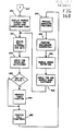
- Fig. 13 is a high level diagram of the vehicle display system software.
- High level functions of the 8088 microprocessor control program are shown in block 200.
- Major functions of the 8031 code are shown in block 201.
- major functions include the graphics control, touch handling, and I/O handling of the system, while the 8031 code controls the communications with the external Poll/Response bus and Random Access bus. Communication between the processors' code is controlled by cooperative routines in each microprocessor.
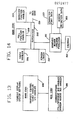
- Fig. 14 is a diagram detailing the breakdown of function within the 8088 control program.
- Major functions include the Supervisor block 205, the Touch handler block 206, the Poll Function handler block 208, the Animation Function handler block 209, and the Screen Loader block 207.
- Additional routines include the interface to the 8031 microprocessor 210, the Graphics Design Language processor block 211, Character Font Data block 213, and Screen Definition Data block 215. Also shown is the CXEDRAW graphics drawing routines block 212. It should be noted that block 215, Screen Definition Data, and block 213, Character Font data, are not executable code but are used by the code to draw and manipulate the screen graphics.
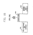
- Fig. 15 is a diagram of the 8031 control program components. Items include the Supervisor program block 220, the Poll/Response bus handler block 221, and the Random Access bus handler block 222. Additional routines support interfacing and data passing to the 8088 routines.
- Communication between the master microprocessor 50 and the slave microprocessor 60 is that of a Command/Response nature.
- the master microprocessor 50 sends a Read command to the slave microprocessor 60 indicating the message ID to be read.
- two extra commands are added to the library of commands between the master and the slave microprocessor. These commands are "Load Message ID table” (LMIDT) and “Load Message Response table” (LMRST). These two commands are issued by the master on power up after the self test by both microprocessors.
- the LMIDT command loads a table of all the bus message ID's that the slave microprocessor must save for that particular vehicle.
- M1ID is the ID of message 1 to be saved
- M1LN is the length (number of bytes of data) of message 1
- M1ADH is the high byte of the 8031 RAM address where message data is to be saved.
- M1ADL is the low byte of the RAM address.
- M1STS is message 1 status byte CMDEND indicates end of table transmission
- the LMRST command loads a table in the slave microprocessor of all the message ID's that the slave must respond to for that particular vehicle.
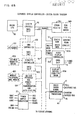
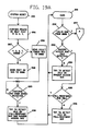
- Figs. 16A and 16B illustrate the logic of the Supervisor control program portion of the 8088 code.
- the 8088 code Supervisor begins execution after the System Reset, block 230. Next the Power On Self Test (P.O.S.T.), block 231, is performed. If the P.O.S.T. detects an error in the system block 232, then the system is halted, block 248, otherwise the 8088 segment registers are initialised, block 233. Communication is established with the 8031, block 234, and the 8031 Power On Self Test results are inspected, block 235. If the 8031 Power On Self Test has detected a failure then the system is also halted, block 248, otherwise system initialisation proceeds with block 236 which initialises the video graphics array registers for the appropriate display device and resolution.
- P.O.S.T. Power On Self Test
- the Interprocessor Data Link circuits are exercised between the 8088 and 8031, block 240. If an error is detected in the data link then the system is halted, blocks 241 and 248, otherwise the Video Gate Array registers and Video Buffer are tested, block 242, and a decision is made whether to proceed or halt, block 243. If no Video Gate Array or Video Buffer error is detected then the 8031 tables which define the message IDs to store and the messages to respond to on the Poll/Response bus are loaded, block 244. Next, system interrupts are enabled and the appropriate information is displayed on the Display unit 3C, block 245. Information is displayed on the screen of the display unit in successive sets of information.
- each set of information desplayed is termed a "frame” (or in some places a “screen”).
- Copending European patent application ( ), based on United States Patent Application No. 945431, filed on 22 December 1986 describes a system for developing frames for the display unit.
- communications is established on the Poll/Response bus, block 246 and the flow continues on Fig. 16B off page by way of connector block 247.
- Fig. 16B the proper screen or frame is displayed and the main supervisor loop is entered, block 250.
- the Poll/Response bus data is then updated, block 251.
- a check is performed for touch key activation, block 252. If any key has been pressed, decision block 253, the particular touch function associated with that key is then performed, block 254, otherwise block 254 is bypassed.
- Poll functions are processed as described in the screen (frame) data for the particular screen (frame) being displayed, block 255.
- Animation functions present on the current screen (frame) are processed, block 256. Background diagnostics are then performed on the system, block 260, and any error detected there or from any other component of the system are handled by block 261.
- Mode switching which is needed, block 262. This could include the operator of the vehicle changing the key switch from Off to Run, to Crank (start), or Accessory modes or by the reception of an error message from another component in the system such as the Body Control systems.
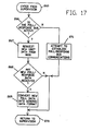
- Fig. 17 details the flow of the Poll/Response bus communication data update routine in the 8088 code.
- This Routine is entered from the Supervisor via block 265 and first checks if the Poll/Response bus communication has been established, block 266. If not yet established, then an attempt is made to do so, block 271. If this attempt fails, then the routine returns to the Supervisor, block 270. Otherwise, if communication has already been established, new Poll/Response bus data is requested from the 8031 microprocessor, block 267. If any new data has been received, block 268, then that data is converted into a generic format and return is passed to the supervisor. Otherwise return is passed to the Supervisor without converting the old data into the generic data format a second time.
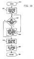
- Fig. 18 illustrates the flow of the Random Access bus command handler in the 8088. It is entered from various routines in the 8088 code at block 275. It first sends the Random Access bus command to the 8031 microprocessor, block 276, and then sends any additional command parameters, blocks 277 and 278, until all parameters have been sent. Next, it sends the Random Access bus command end, block 279. It then gets command status from the 8031 microprocessor which indicates command execution state or completion of the command by the 8031 microprocessor, block 280, and then returns to the calling routine, block 281.
- Figs. 19A, 19B and 19C illustrate the flow of the 8031 Supervisor program. It begins with system reset, block 285, performs its Power On Self Test (P.O.S.T.), block 286, and sends the results of the P.O.S.T to the 8088 microprocessor, blocks 287, 288, or 298, depending on whether an error is detected or not. It then waits for the Continue command from the 8088 to be received, block 289. After the Continue command is received, the 8031 Supervisor tries to detect an idle condition on the Poll/Response bus and Random Access bus before it enters the Main Supervisor loop, 291.
- P.O.S.T. Power On Self Test
- block 292 checks for a valid command from the 8088 processor. If no valid command is received, a background idle detection routine is invoked, if the main idle detect routines were unsuccessful before entering the Main Supervisor loop. These blocks include 293-296, otherwise block 292 is continually executed until a valid command is received from the 8088. When a valid command is received, block 292 passes control to the off page connector, block 297, which continues on Fig. 19B by reading in the command from the command port, block 300, and then determining which command type has been received. Six commands designated 0, 1, 2, 3, 4, 5, are shown in Fig. 19B.
- These commands include Diagnostic command (0), Load Message ID table command (1), Load Message Response table command (2), Command End (3), Read Poll/Response bus data (4), and Store Poll/Response bus response message (5). Additional commands 7 and 8 are shown in Fig. 19C. They include the Process command OK command (7) and the Random Access bus command (8). After each command is executed the 8031 code returns control to the Main Supervisor loop 291 to look for more commands, by way of blocks 291 a-g.
- a microprocessor-based touch controller replaces a switch decode card version and allows for considerable improvement in system cost, reliability, and performance.
- the automotive display assembly described herein comprises, in addition to the Display controller, a monitor display, a display oriented soft touch input device, a set of discrete hard switches located below the monitor display, and a touch controller serving as a decode logic board.
- the controller logic decodes the soft (touch input) and the hard switch matrices. This display assembly meets automotive environmental requirements.
- the display assembly comprises touch controller card 330 interconnected with the Display controller 34, the CRT monitor 36, the soft switch matrix 67, and the discrete (hard) switch matrix 68 with backlighting 44.
- Touch controller 330 electrically interfaces the switch matrices to the Display controller 34, incorporates an annunciator for audible feedback, and acts as a pass-through for signals from Display controller 34 and wiring harness to monitor 36.
- Fig. 21 is a block diagram of one version of a switch decode card 340.
- the card scans an 8x8 soft/hard switch matrix connected by way of junction connectors J2 and J3 and detects a switch closure allowing a Display controller (such as Display controller 34) to identify an activated switch.
- the rows and columns of the matrix are driven by the outputs of a 4 to 16 decoder 341.
- Outputs 0 through 7 of the decoder 341 drive the respective rows, and outputs 8 through 15 drive the respective columns.
- decoder 341 Only one output of decoder 341 is on (active low) at any one time with the rest of the outputs tristated.
- the four inputs of the 4 to 16 decoder 341 are driven by four data lines D0-D3 via bus 343 from the Display controller by way of connector J1.
- the Display controller scans the rows of the matrix by incrementing D0-D2 while keeping D3 low.
- Line D3 when low, enables the column detect logic 349 to drive the detect input signal (REIN) on line 346 to the Display controller.
- REIN detect input signal
- the Display controller reads REIN after each increment for a possible switch hit on the columns.
- the low level placed by the decoder 341 on the row associated with that specific switch is transferred to the corresponding column. This action drives REIN low, causing the Display controller to save the specific row number and to start scanning the columns in order to determine the column number for the activated switch.
- the switch decode card 340 contains a timer oscillator circuit 350 to drive a chime 351 which is activated by the Display controller when a valid switch hit occurs.
- Fig. 22 is a block diagram of another version of touch controller, i.e., a microprocessor-based touch controller 330 within its system configuration.
- Touch controller 330 incorporates an Intel microcontroller 360 which includes an 80C51 microprocessor, 4K bytes of ROM, 128 bytes of RAM, two 16 bit timers/counters, four 8 bit parallel ports, and a serial port all on-board.
- the touch controller 330 interfaces to the Display controller 34 over the Serial Data Link (SDL) line 362 through connector J1 and the serial port (Driver/Receivers) within the 80C51.
- SDL Serial Data Link
- the parallel ports P0, P1, P2 of the 80C51 are used to drive the rows and columns of the switch matrices 67 and 68 and backlighting 44 via connectors J2 and J3.
- One of the timers within the 80C51 generates the input clock signal for the chime 351.
- this design incorporates a power conditioning circuit 365 that generates regulated +5 volts from the Display controller. This circuit provides for protection of the +5 volts line against short circuits to battery or ground.
- the Display controller performs the switch scanning and diagnostics.
- the 80C51 based version in Fig. 22 relieves the Display controller of the above mentioned tasks which account for forty percent of the Display controller overhead.
- This version includes fault detection and isolation due to the added on-board intelligence of the 80C51.
- the parallel port approach of the version in Fig. 21 is replaced by a serial port approach, thus reducing the amount of interface wiring.
Landscapes
- Engineering & Computer Science (AREA)
- Theoretical Computer Science (AREA)
- Physics & Mathematics (AREA)
- General Engineering & Computer Science (AREA)
- Human Computer Interaction (AREA)
- General Physics & Mathematics (AREA)
- Mechanical Engineering (AREA)
- Thermal Sciences (AREA)
- Management, Administration, Business Operations System, And Electronic Commerce (AREA)
- Instrument Panels (AREA)
- Digital Computer Display Output (AREA)
- Small-Scale Networks (AREA)
- Communication Control (AREA)
- Traffic Control Systems (AREA)
- Combined Controls Of Internal Combustion Engines (AREA)
- Control Of Indicators Other Than Cathode Ray Tubes (AREA)
- Controls And Circuits For Display Device (AREA)
Applications Claiming Priority (2)
| Application Number | Priority Date | Filing Date | Title |
|---|---|---|---|
| US06/945,053 US4787040A (en) | 1986-12-22 | 1986-12-22 | Display system for automotive vehicle |
| US945053 | 1986-12-22 |
Publications (2)
| Publication Number | Publication Date |
|---|---|
| EP0272877A2 true EP0272877A2 (de) | 1988-06-29 |
| EP0272877A3 EP0272877A3 (de) | 1991-05-02 |
Family
ID=25482545
Family Applications (1)
| Application Number | Title | Priority Date | Filing Date |
|---|---|---|---|
| EP19870311087 Withdrawn EP0272877A3 (de) | 1986-12-22 | 1987-12-16 | Anzeigesystem für Fahrzeug |
Country Status (3)
| Country | Link |
|---|---|
| US (1) | US4787040A (de) |
| EP (1) | EP0272877A3 (de) |
| JP (1) | JPS63163700A (de) |
Cited By (14)
| Publication number | Priority date | Publication date | Assignee | Title |
|---|---|---|---|---|
| FR2674199A1 (fr) * | 1991-03-22 | 1992-09-25 | Daimler Benz Ag | Poste de travail a ecran dans un vehicule. |
| EP0482959A3 (en) * | 1990-10-25 | 1993-06-02 | Pioneer Electronic Corporation | System for data communication |
| GB2264613A (en) * | 1992-01-17 | 1993-09-01 | Pioneer Electronic Corp | Car telephone/entertainment system |
| WO1995013577A1 (en) * | 1993-11-03 | 1995-05-18 | Computec Oy | Computer for a vehicle |
| EP0779564A3 (de) * | 1995-12-11 | 1998-04-01 | Western Atlas Inc. | Automatisiertes Steuerungssystem mit zweisprachiger Zustandsanzeige |
| WO1999044302A1 (de) * | 1998-02-27 | 1999-09-02 | Sommer Allibert-Lignotock Gmbh | Freisprechanlage für ein mobiltelefon |
| WO2001052049A1 (de) * | 2000-01-12 | 2001-07-19 | Volkswagen Aktiengesellschaft | Elektronisches system |
| EP1172239A3 (de) * | 2000-07-12 | 2004-02-18 | Volkswagen Aktiengesellschaft | System zur manuellen Einstellung der Dämpfung eines Kraftfahrzeug-Fahrwerkes |
| WO2005120880A1 (de) | 2004-06-11 | 2005-12-22 | Volkswagen Aktiengesellschaft | Anzeigevorrichtung für ein kraftfahrzeug |
| EP1712424A3 (de) * | 2005-04-11 | 2007-07-18 | Denso Corporation | Kraftfahrzeugsteuergerät |
| US7382237B2 (en) | 2004-12-30 | 2008-06-03 | Volkswagen Ag | Display arrangement for a vehicle |
| EP1444586B1 (de) * | 2001-11-13 | 2011-01-05 | Airbus Operations GmbH | Bedienungsvorrichtung für ein kabinensystem in einem flugzeug |
| CN103507729A (zh) * | 2013-09-22 | 2014-01-15 | 重庆长安汽车股份有限公司 | 电动汽车整车控制器电源自保持系统 |
| CN103434462B (zh) * | 2013-08-26 | 2015-09-30 | 浙江吉利汽车研究院有限公司 | 汽车智能控制方法和控制系统 |
Families Citing this family (127)
| Publication number | Priority date | Publication date | Assignee | Title |
|---|---|---|---|---|
| JP2516387Y2 (ja) * | 1987-08-19 | 1996-11-06 | 三洋電機株式会社 | 情報ファイル装置 |
| US5175926A (en) * | 1988-12-22 | 1993-01-05 | Ford Motor Company | Method of manufacturing an automotive sound system |
| US5127057A (en) * | 1988-12-22 | 1992-06-30 | Ford Motor Company | Integral sound system having interchangeable modules with separate microcontrollers |
| US5132905A (en) * | 1988-12-28 | 1992-07-21 | Nissan Motor Company Limited | System and method applicable to vehicles for communicating between data processing stations |
| US5325483A (en) * | 1989-04-07 | 1994-06-28 | Hitachi, Ltd. | Image information retrieval network system |
| JPH0326639U (de) * | 1989-07-25 | 1991-03-18 | ||
| US5151855A (en) * | 1989-10-19 | 1992-09-29 | Saturn Corporation | Multiple microprocessor single power supply system shutdown |
| JP3106495B2 (ja) * | 1990-11-21 | 2000-11-06 | ソニー株式会社 | ホームバス制御装置 |
| US5355007A (en) * | 1990-11-23 | 1994-10-11 | Texas Instruments Incorporated | Devices for non-volatile memory, systems and methods |
| JPH0816877B2 (ja) * | 1991-06-10 | 1996-02-21 | インターナショナル・ビジネス・マシーンズ・コーポレイション | データ処理システム用資源データの実時間捕獲及び減縮方法及びシステム |
| US5437464A (en) * | 1991-08-30 | 1995-08-01 | Kabushiki Kaisha Sega Enterprises | Data reading and image processing system for CD-ROM |
| US7084859B1 (en) | 1992-09-18 | 2006-08-01 | Pryor Timothy R | Programmable tactile touch screen displays and man-machine interfaces for improved vehicle instrumentation and telematics |
| US7098891B1 (en) * | 1992-09-18 | 2006-08-29 | Pryor Timothy R | Method for providing human input to a computer |
| US5513107A (en) * | 1992-12-17 | 1996-04-30 | Ford Motor Company | Methods and apparatus for controlling operating subsystems of a motor vehicle |
| US5471193A (en) * | 1993-07-12 | 1995-11-28 | Phillips Plastics Corporation | Tamper-resistant vehicle event recorder |
| DE4338171C1 (de) * | 1993-11-09 | 1995-04-20 | Daimler Benz Ag | Tastatur- und Anzeigesystem |
| WO1995019030A1 (en) * | 1994-01-05 | 1995-07-13 | Pois, Inc. | Apparatus and method for a personal onboard information system |
| US7126583B1 (en) | 1999-12-15 | 2006-10-24 | Automotive Technologies International, Inc. | Interactive vehicle display system |
| US5555502A (en) * | 1994-05-11 | 1996-09-10 | Geo Ventures | Display and control apparatus for the electronic systems of a motor vehicle |
| US9513744B2 (en) | 1994-08-15 | 2016-12-06 | Apple Inc. | Control systems employing novel physical controls and touch screens |
| US7489303B1 (en) * | 2001-02-22 | 2009-02-10 | Pryor Timothy R | Reconfigurable instrument panels |
| US5555172A (en) * | 1994-08-22 | 1996-09-10 | Prince Corporation | User interface for controlling accessories and entering data in a vehicle |
| US20060284839A1 (en) * | 1999-12-15 | 2006-12-21 | Automotive Technologies International, Inc. | Vehicular Steering Wheel with Input Device |
| US8228305B2 (en) | 1995-06-29 | 2012-07-24 | Apple Inc. | Method for providing human input to a computer |
| US20090273574A1 (en) * | 1995-06-29 | 2009-11-05 | Pryor Timothy R | Programmable tactile touch screen displays and man-machine interfaces for improved vehicle instrumentation and telematics |
| JP3355879B2 (ja) * | 1995-08-01 | 2002-12-09 | 株式会社デンソー | 制御回路 |
| US5794164A (en) * | 1995-11-29 | 1998-08-11 | Microsoft Corporation | Vehicle computer system |
| US6134508A (en) * | 1996-07-01 | 2000-10-17 | Brandt; Jobst | Simplified system for displaying user-selected functions in a bicycle computer or similar device |
| US5946055A (en) * | 1996-08-16 | 1999-08-31 | Rosen Product Development, Inc. | Display unit |
| US6246449B1 (en) | 1996-08-16 | 2001-06-12 | Rosen Products Llc | Display unit |
| US5916288A (en) * | 1996-09-03 | 1999-06-29 | Ut Automotive Dearborn, Inc. | Multi-functional control switch arrangement |
| US6026344A (en) * | 1997-02-13 | 2000-02-15 | Spx Corporation | Diagnosis method for vehicle systems |
| US6324592B1 (en) | 1997-02-25 | 2001-11-27 | Keystone Aerospace | Apparatus and method for a mobile computer architecture and input/output management system |
| US6058485A (en) * | 1997-07-29 | 2000-05-02 | Lsi Logic Corporation | Method and apparatus for managing power consumption of a digitizing panel |
| GB9722766D0 (en) | 1997-10-28 | 1997-12-24 | British Telecomm | Portable computers |
| US6104375A (en) * | 1997-11-07 | 2000-08-15 | Datascope Investment Corp. | Method and device for enhancing the resolution of color flat panel displays and cathode ray tube displays |
| US7085710B1 (en) * | 1998-01-07 | 2006-08-01 | Microsoft Corporation | Vehicle computer system audio entertainment system |
| US9239673B2 (en) | 1998-01-26 | 2016-01-19 | Apple Inc. | Gesturing with a multipoint sensing device |
| US8479122B2 (en) | 2004-07-30 | 2013-07-02 | Apple Inc. | Gestures for touch sensitive input devices |
| US7614008B2 (en) | 2004-07-30 | 2009-11-03 | Apple Inc. | Operation of a computer with touch screen interface |
| US9292111B2 (en) | 1998-01-26 | 2016-03-22 | Apple Inc. | Gesturing with a multipoint sensing device |
| US6013956A (en) * | 1998-02-23 | 2000-01-11 | Cooper Automotive Products, Inc. | Touch control switches for vehicles |
| US6144114A (en) * | 1998-03-25 | 2000-11-07 | Lear Automotive Dearborn, Inc. | Auto PC wallet PC faceplate |
| US6185484B1 (en) | 1998-08-05 | 2001-02-06 | Eaton Corporation | Method of operating a motor vehicle management computer system |
| US6434450B1 (en) * | 1998-10-19 | 2002-08-13 | Diversified Software Industries, Inc. | In-vehicle integrated information system |
| DE19907795A1 (de) * | 1999-02-24 | 2000-09-14 | Daimler Chrysler Ag | Verfahren zur Unterstützung eines Benutzers eines Kraftfahrzeugs bei der Bedienung von Komponenten des Kraftfahrzeugs sowie eine zugehörige Vorrichtung |
| US6292236B1 (en) | 1999-03-26 | 2001-09-18 | Rosen Products Llc | Automotive-ceiling-mounted monitor |
| US6253122B1 (en) * | 1999-06-14 | 2001-06-26 | Sun Microsystems, Inc. | Software upgradable dashboard |
| US6370449B1 (en) | 1999-06-14 | 2002-04-09 | Sun Microsystems, Inc. | Upgradable vehicle component architecture |
| US6754183B1 (en) | 1999-06-14 | 2004-06-22 | Sun Microsystems, Inc. | System and method for integrating a vehicle subnetwork into a primary network |
| US6362730B2 (en) | 1999-06-14 | 2002-03-26 | Sun Microsystems, Inc. | System and method for collecting vehicle information |
| US6975612B1 (en) | 1999-06-14 | 2005-12-13 | Sun Microsystems, Inc. | System and method for providing software upgrades to a vehicle |
| US6507810B2 (en) | 1999-06-14 | 2003-01-14 | Sun Microsystems, Inc. | Integrated sub-network for a vehicle |
| USD446507S1 (en) | 1999-06-18 | 2001-08-14 | Rosen Products Llc | Ceiling-mounted monitor |
| DE19939631A1 (de) | 1999-08-20 | 2001-02-22 | Nokia Mobile Phones Ltd | Multimediaeinheit |
| US6601176B1 (en) * | 1999-09-08 | 2003-07-29 | Visteon Global Technologies, Inc. | Automotive computer system and method whereby responsive to detecting engine cranking main processor enters a suspend mode and current state of devices are stored in volatile memory |
| US6381133B1 (en) * | 1999-10-25 | 2002-04-30 | Jack Chen | Automobile computer dock |
| US6091658A (en) * | 1999-11-01 | 2000-07-18 | Ford Global Technologies, Inc. | Nonvolatile memory implementation for electronic devices |
| US8482535B2 (en) | 1999-11-08 | 2013-07-09 | Apple Inc. | Programmable tactile touch screen displays and man-machine interfaces for improved vehicle instrumentation and telematics |
| DE19955890B4 (de) * | 1999-11-20 | 2006-10-05 | Robert Bosch Gmbh | Verfahren und Vorrichtung zur Ausgabe von Bedienhinweisen |
| US20080122799A1 (en) * | 2001-02-22 | 2008-05-29 | Pryor Timothy R | Human interfaces for vehicles, homes, and other applications |
| US8576199B1 (en) | 2000-02-22 | 2013-11-05 | Apple Inc. | Computer control systems |
| SE0001491D0 (sv) * | 2000-04-25 | 2000-04-25 | Scania Cv Ab | Funktionsuppdelad deplexkommunikationsbuss |
| US20030154255A1 (en) * | 2000-05-05 | 2003-08-14 | Hans-Joachim Platte | Method for reducing the spread of computer viruses in an electronic mail network |
| IL136652A0 (en) * | 2000-06-08 | 2001-06-14 | Arlinsky David | A closed-loop control system in a car |
| US6570106B1 (en) | 2000-07-10 | 2003-05-27 | Steven L. Merrick | Movable electric switches that move to reveal underlying control areas |
| US9084076B2 (en) | 2001-02-16 | 2015-07-14 | Intelligent Technologies International, Inc. | Techniques for obtaining information about objects |
| US20080024463A1 (en) * | 2001-02-22 | 2008-01-31 | Timothy Pryor | Reconfigurable tactile control display applications |
| US7916124B1 (en) | 2001-06-20 | 2011-03-29 | Leapfrog Enterprises, Inc. | Interactive apparatus using print media |
| USD455130S1 (en) | 2001-06-21 | 2002-04-02 | Decatur Electronics, Inc. | Interior roof mounted video system |
| DE10146979B4 (de) * | 2001-09-24 | 2005-09-15 | Harman Becker Automotive Systems (Becker Division) Gmbh | Autorundfunkempfänger mit mehreren Funktionstasten |
| US20030222982A1 (en) * | 2002-03-28 | 2003-12-04 | Hamdan Majil M. | Integrated video/data information system and method for application to commercial vehicles to enhance driver awareness |
| JP2004050650A (ja) * | 2002-07-19 | 2004-02-19 | Nec Corp | 半導体装置、画像出力装置、および機能素子の駆動方法 |
| KR100501354B1 (ko) * | 2002-08-08 | 2005-07-18 | 현대자동차주식회사 | 자동차 멀티 펑션 스위치의 페일 세이프 해제 방법 |
| US7358963B2 (en) | 2002-09-09 | 2008-04-15 | Apple Inc. | Mouse having an optically-based scrolling feature |
| US6871121B2 (en) | 2002-10-07 | 2005-03-22 | Blink Engineering Corp. | Entertainment system on-board a vehicle for visualizing on a display real-time vehicle data |
| US20070035625A9 (en) * | 2002-12-20 | 2007-02-15 | Hamdan Majed M | Vehicle video processing system |
| US20040229195A1 (en) * | 2003-03-18 | 2004-11-18 | Leapfrog Enterprises, Inc. | Scanning apparatus |
| EP1626877A4 (de) | 2003-03-31 | 2011-08-10 | Timothy R Pryor | Rekonfigurierbare fahrzeugarmaturenbretter |
| US20050012599A1 (en) * | 2003-07-17 | 2005-01-20 | Dematteo Bryan N. | Reconfigurable vehicle display |
| US20050083187A1 (en) * | 2003-10-16 | 2005-04-21 | Siemens Vdo Automotive Corporation | Flat panel color cluster |
| US20050093975A1 (en) * | 2003-10-30 | 2005-05-05 | Hamdan Majed M. | Adaptation of vision systems for commerical vehicles |
| US20060067576A1 (en) * | 2004-03-17 | 2006-03-30 | James Marggraff | Providing a user interface having interactive elements on a writable surface |
| US7831933B2 (en) | 2004-03-17 | 2010-11-09 | Leapfrog Enterprises, Inc. | Method and system for implementing a user interface for a device employing written graphical elements |
| US20060127872A1 (en) * | 2004-03-17 | 2006-06-15 | James Marggraff | Method and device for associating a user writing with a user-writable element |
| US20060125805A1 (en) * | 2004-03-17 | 2006-06-15 | James Marggraff | Method and system for conducting a transaction using recognized text |
| US20060066591A1 (en) * | 2004-03-17 | 2006-03-30 | James Marggraff | Method and system for implementing a user interface for a device through recognized text and bounded areas |
| US7853193B2 (en) * | 2004-03-17 | 2010-12-14 | Leapfrog Enterprises, Inc. | Method and device for audibly instructing a user to interact with a function |
| US7478492B2 (en) * | 2004-05-14 | 2009-01-20 | Madonia Joseph R | Integrated flat panel display for mounting to exterior surfaces of motor vehicles |
| JP4508728B2 (ja) * | 2004-06-07 | 2010-07-21 | アルパイン株式会社 | 車載用電子機器およびその機器におけるディジタル放送の表示方法 |
| US8381135B2 (en) | 2004-07-30 | 2013-02-19 | Apple Inc. | Proximity detector in handheld device |
| JP2006047534A (ja) * | 2004-08-03 | 2006-02-16 | Alpine Electronics Inc | 表示制御システム |
| US20100231506A1 (en) * | 2004-09-07 | 2010-09-16 | Timothy Pryor | Control of appliances, kitchen and home |
| US7020992B1 (en) | 2004-10-25 | 2006-04-04 | Christie Joel A | Message display assembly for a vehicle |
| SI1657529T1 (sl) * | 2004-11-15 | 2010-09-30 | Siem Srl | Digitalni prikazovalnik |
| USD537122S1 (en) | 2005-05-18 | 2007-02-20 | Silva David N | Combined keyboard and digital display device |
| US7593792B2 (en) * | 2005-06-01 | 2009-09-22 | Delphi Technologies, Inc. | Vehicle information system with remote communicators in a network environment |
| US7352282B2 (en) * | 2005-07-12 | 2008-04-01 | Yazaki Corporation | Communication system |
| US7922099B1 (en) | 2005-07-29 | 2011-04-12 | Leapfrog Enterprises, Inc. | System and method for associating content with an image bearing surface |
| US7317385B2 (en) * | 2005-08-02 | 2008-01-08 | Johnson Controls Technology Company | In-vehicle animation bypass system and method |
| US7936339B2 (en) * | 2005-11-01 | 2011-05-03 | Leapfrog Enterprises, Inc. | Method and system for invoking computer functionality by interaction with dynamically generated interface regions of a writing surface |
| US7640085B2 (en) * | 2005-11-10 | 2009-12-29 | Gm Global Technology Operations, Inc. | Method and apparatus to provide vehicle information to a requestor |
| US20070136694A1 (en) * | 2005-12-09 | 2007-06-14 | Microsoft Corporation | Color and context-adaptable hardware button |
| US8077147B2 (en) | 2005-12-30 | 2011-12-13 | Apple Inc. | Mouse with optical sensing surface |
| US8599143B1 (en) * | 2006-02-06 | 2013-12-03 | Leapfrog Enterprises, Inc. | Switch configuration for detecting writing pressure in a writing device |
| US8261967B1 (en) | 2006-07-19 | 2012-09-11 | Leapfrog Enterprises, Inc. | Techniques for interactively coupling electronic content with printed media |
| US7844915B2 (en) | 2007-01-07 | 2010-11-30 | Apple Inc. | Application programming interfaces for scrolling operations |
| JP4997988B2 (ja) * | 2007-01-23 | 2012-08-15 | アイシン・エィ・ダブリュ株式会社 | スイッチ制御装置およびスイッチ制御方法 |
| JP4787782B2 (ja) * | 2007-03-30 | 2011-10-05 | 富士通コンポーネント株式会社 | 機器操作システム、制御装置 |
| JP5005413B2 (ja) * | 2007-04-09 | 2012-08-22 | 株式会社東海理化電機製作所 | 車載機器制御装置 |
| US20100073132A1 (en) * | 2008-09-19 | 2010-03-25 | Delphi Technologies, Inc. | Ignition system for a vehicle |
| US8207841B2 (en) * | 2008-10-28 | 2012-06-26 | Ford Global Technologies, Llc | Vehicle information display and method |
| US7976346B2 (en) * | 2009-03-06 | 2011-07-12 | Cisco Technology, Inc. | Interface connection management using a removable adapter for communications equipment |
| US8299938B2 (en) * | 2009-09-08 | 2012-10-30 | Rosemount Inc. | Projected instrument displays for field mounted process instruments |
| US8577487B2 (en) * | 2010-02-23 | 2013-11-05 | Paccar Inc | Customized instrument evaluation and ordering tool |
| US8483907B2 (en) * | 2010-02-23 | 2013-07-09 | Paccar Inc | Customizable graphical display |
| US9254750B2 (en) * | 2010-02-23 | 2016-02-09 | Paccar Inc | Graphical display with scrollable graphical elements |
| US20110209079A1 (en) * | 2010-02-23 | 2011-08-25 | Paccar Inc. | Graphical display with hierarchical gauge placement |
| US8490005B2 (en) * | 2010-02-23 | 2013-07-16 | Paccar Inc | Visual enhancement for instrument panel |
| US20120283914A1 (en) * | 2011-05-05 | 2012-11-08 | Karwaczynski Krzysztof W | Vehicle steering wheel control system having integrated electronic control unit |
| EP2602782A1 (de) * | 2011-12-08 | 2013-06-12 | Johnson Controls Automotive Electronics SAS | Anzeigesystem |
| JP5565421B2 (ja) * | 2012-02-07 | 2014-08-06 | 株式会社デンソー | 車載操作装置 |
| US9280141B2 (en) * | 2012-04-11 | 2016-03-08 | Bose Corporation | Controlling table music system |
| US9868353B2 (en) * | 2014-01-06 | 2018-01-16 | Ford Global Technologies, Llc | In-vehicle configurable soft switches |
| US10134261B1 (en) * | 2017-11-02 | 2018-11-20 | Ford Global Technologies, Llc | Method and apparatus for vehicular item tracking |
| JP7047444B2 (ja) | 2018-02-16 | 2022-04-05 | トヨタ自動車株式会社 | 車両制御装置、電子制御ユニット、制御方法、制御プログラム、車両、otaマスタ、システム及びセンタ |
| CN114077473A (zh) * | 2021-09-30 | 2022-02-22 | 北京罗克维尔斯科技有限公司 | 通信方法、装置及系统 |
Family Cites Families (6)
| Publication number | Priority date | Publication date | Assignee | Title |
|---|---|---|---|---|
| US4535330A (en) * | 1982-04-29 | 1985-08-13 | Honeywell Information Systems Inc. | Bus arbitration logic |
| GB2130855B (en) * | 1982-11-03 | 1986-06-04 | Ferranti Plc | Information display system |
| US4464933A (en) * | 1982-11-15 | 1984-08-14 | International Harvester Co. | Steering console providing digital readout displays |
| JPS59174713A (ja) * | 1983-03-25 | 1984-10-03 | Nippon Denso Co Ltd | 車載用地図表示装置 |
| JPS60196617A (ja) * | 1984-03-19 | 1985-10-05 | Mitsubishi Electric Corp | 車載ナビゲ−シヨン装置 |
| FR2578067B1 (fr) * | 1985-02-27 | 1988-04-15 | Renault | Systeme de distribution commandee d'energie electrique dans un vehicule automobile |
-
1986
- 1986-12-22 US US06/945,053 patent/US4787040A/en not_active Expired - Lifetime
-
1987
- 1987-09-18 JP JP62232746A patent/JPS63163700A/ja active Granted
- 1987-12-16 EP EP19870311087 patent/EP0272877A3/de not_active Withdrawn
Cited By (20)
| Publication number | Priority date | Publication date | Assignee | Title |
|---|---|---|---|---|
| EP0482959A3 (en) * | 1990-10-25 | 1993-06-02 | Pioneer Electronic Corporation | System for data communication |
| US5436851A (en) * | 1990-10-25 | 1995-07-25 | Pioneer Electronic Corporation | System for data communication |
| FR2674199A1 (fr) * | 1991-03-22 | 1992-09-25 | Daimler Benz Ag | Poste de travail a ecran dans un vehicule. |
| GB2264613A (en) * | 1992-01-17 | 1993-09-01 | Pioneer Electronic Corp | Car telephone/entertainment system |
| WO1995013577A1 (en) * | 1993-11-03 | 1995-05-18 | Computec Oy | Computer for a vehicle |
| EP0779564A3 (de) * | 1995-12-11 | 1998-04-01 | Western Atlas Inc. | Automatisiertes Steuerungssystem mit zweisprachiger Zustandsanzeige |
| US5828992A (en) * | 1995-12-11 | 1998-10-27 | Unova Ip Corp. | Automated control system with bilingual status display |
| WO1999044302A1 (de) * | 1998-02-27 | 1999-09-02 | Sommer Allibert-Lignotock Gmbh | Freisprechanlage für ein mobiltelefon |
| US6832142B2 (en) | 2000-01-12 | 2004-12-14 | Volkswagen Ag | Electronic system |
| WO2001052049A1 (de) * | 2000-01-12 | 2001-07-19 | Volkswagen Aktiengesellschaft | Elektronisches system |
| EP1172239A3 (de) * | 2000-07-12 | 2004-02-18 | Volkswagen Aktiengesellschaft | System zur manuellen Einstellung der Dämpfung eines Kraftfahrzeug-Fahrwerkes |
| EP1444586B1 (de) * | 2001-11-13 | 2011-01-05 | Airbus Operations GmbH | Bedienungsvorrichtung für ein kabinensystem in einem flugzeug |
| WO2005120880A1 (de) | 2004-06-11 | 2005-12-22 | Volkswagen Aktiengesellschaft | Anzeigevorrichtung für ein kraftfahrzeug |
| US9205743B2 (en) | 2004-06-11 | 2015-12-08 | Volkswagen Ag | Display device for a motor vehicle |
| US7382237B2 (en) | 2004-12-30 | 2008-06-03 | Volkswagen Ag | Display arrangement for a vehicle |
| EP1712424A3 (de) * | 2005-04-11 | 2007-07-18 | Denso Corporation | Kraftfahrzeugsteuergerät |
| US8164214B2 (en) | 2005-04-11 | 2012-04-24 | Denso Corporation | Vehicle control apparatus having function for preventing erroneous operation due to delay in activation of other vehicle control apparatus |
| CN103434462B (zh) * | 2013-08-26 | 2015-09-30 | 浙江吉利汽车研究院有限公司 | 汽车智能控制方法和控制系统 |
| CN103507729A (zh) * | 2013-09-22 | 2014-01-15 | 重庆长安汽车股份有限公司 | 电动汽车整车控制器电源自保持系统 |
| CN103507729B (zh) * | 2013-09-22 | 2015-10-07 | 重庆长安汽车股份有限公司 | 电动汽车整车控制器电源自保持系统 |
Also Published As
| Publication number | Publication date |
|---|---|
| JPH0440732B2 (de) | 1992-07-06 |
| EP0272877A3 (de) | 1991-05-02 |
| JPS63163700A (ja) | 1988-07-07 |
| US4787040A (en) | 1988-11-22 |
Similar Documents
| Publication | Publication Date | Title |
|---|---|---|
| EP0272877A2 (de) | Anzeigesystem für Fahrzeug | |
| US4811240A (en) | System for creating and controlling interactive graphic display screens | |
| CN111976482B (zh) | 一种车载仪表屏和中控娱乐屏的双屏交互系统及方法 | |
| US20010041956A1 (en) | Automobile information system | |
| GB2216295A (en) | Diagnostic system for the electronic control system of an automotive engine | |
| JPH1185219A (ja) | プログラマブルコントローラ | |
| EP0554975B1 (de) | Gerätunabhängige Schnittstelle für graphische Anzeigegeräte | |
| EP0430219A2 (de) | Verfahren und System zum Wiederaufnahmesteuerungsprozess in einer Rechnereinheit, die eine Erweiterungseinheit verbinden kann | |
| US6184904B1 (en) | Central processing unit for a process control system | |
| US6466216B1 (en) | Computer system with optimized display control | |
| US20070067517A1 (en) | Integrated physics engine and related graphics processing system | |
| US5504920A (en) | Video driver system for communicating device specific primitive commands to multiple video controller types | |
| US6125456A (en) | Microcomputer with self-diagnostic unit | |
| JPS62131343A (ja) | 車載電子装置の診断表示方式 | |
| US5333259A (en) | Graphic information processing system having a RISC CPU for displaying information in a window | |
| JP3352557B2 (ja) | 電子制御ユニットのモニタ方法 | |
| JP2000194580A (ja) | Cpu開発支援装置 | |
| EP4586072A1 (de) | Verfahren zur zuordnung von kalibrierungssignalen zu plattensteuerungen, computerlesbares speichermedium und elektronische vorrichtung | |
| CN212570348U (zh) | 一种多屏显示检测装置 | |
| JPH0530197Y2 (de) | ||
| CN118349155A (zh) | 标定信号用面板控件关联系统、标定系统及方法 | |
| JPH06290074A (ja) | 電子制御ユニットの調整装置 | |
| CN119058560A (zh) | 车载装置以及该车载装置执行的方法 | |
| JP3179388B2 (ja) | 情報処理装置の診断回路および診断方法 | |
| CN116069279A (zh) | 一种屏幕显示的方法以及车载终端 |
Legal Events
| Date | Code | Title | Description |
|---|---|---|---|
| PUAI | Public reference made under article 153(3) epc to a published international application that has entered the european phase |
Free format text: ORIGINAL CODE: 0009012 |
|
| AK | Designated contracting states |
Kind code of ref document: A2 Designated state(s): DE FR GB |
|
| 17P | Request for examination filed |
Effective date: 19881022 |
|
| PUAL | Search report despatched |
Free format text: ORIGINAL CODE: 0009013 |
|
| AK | Designated contracting states |
Kind code of ref document: A3 Designated state(s): DE FR GB |
|
| STAA | Information on the status of an ep patent application or granted ep patent |
Free format text: STATUS: THE APPLICATION HAS BEEN WITHDRAWN |
|
| 18W | Application withdrawn |
Withdrawal date: 19930107 |
|
| RIN1 | Information on inventor provided before grant (corrected) |
Inventor name: SLATER, FREDERICK T. Inventor name: SCHWARTZ, NICHOLAS J. Inventor name: TROOP, WILLIAM C. Inventor name: MILLER, ROBERT V. Inventor name: BALLOU, RICHARD W. Inventor name: PATE, THOMAS K. Inventor name: STRICKLAND, STANFORD A. |