EP0272897A2 - Transportsystem vom Typ eines schwebenden Trägers - Google Patents
Transportsystem vom Typ eines schwebenden Trägers Download PDFInfo
- Publication number
- EP0272897A2 EP0272897A2 EP87311213A EP87311213A EP0272897A2 EP 0272897 A2 EP0272897 A2 EP 0272897A2 EP 87311213 A EP87311213 A EP 87311213A EP 87311213 A EP87311213 A EP 87311213A EP 0272897 A2 EP0272897 A2 EP 0272897A2
- Authority
- EP
- European Patent Office
- Prior art keywords
- carrier
- rail
- coupling
- guide rail
- transportation system
- Prior art date
- Legal status (The legal status is an assumption and is not a legal conclusion. Google has not performed a legal analysis and makes no representation as to the accuracy of the status listed.)
- Granted
Links
- 230000008878 coupling Effects 0.000 claims description 166
- 238000010168 coupling process Methods 0.000 claims description 166
- 238000005859 coupling reaction Methods 0.000 claims description 166
- 230000005291 magnetic effect Effects 0.000 claims description 83
- 238000006243 chemical reaction Methods 0.000 claims description 15
- 239000003302 ferromagnetic material Substances 0.000 claims description 13
- 238000001514 detection method Methods 0.000 claims description 12
- 239000000969 carrier Substances 0.000 claims description 11
- 230000006698 induction Effects 0.000 claims description 11
- 230000004907 flux Effects 0.000 claims description 10
- 239000000696 magnetic material Substances 0.000 claims 1
- 238000009434 installation Methods 0.000 abstract description 4
- 230000005294 ferromagnetic effect Effects 0.000 abstract description 3
- 238000012986 modification Methods 0.000 description 6
- 230000004048 modification Effects 0.000 description 6
- 238000004519 manufacturing process Methods 0.000 description 3
- 230000008859 change Effects 0.000 description 2
- 239000000428 dust Substances 0.000 description 2
- 241000217377 Amblema plicata Species 0.000 description 1
- 238000007689 inspection Methods 0.000 description 1
- 230000003993 interaction Effects 0.000 description 1
- 238000012423 maintenance Methods 0.000 description 1
- 230000001902 propagating effect Effects 0.000 description 1
Images


Classifications
-
- B—PERFORMING OPERATIONS; TRANSPORTING
- B60—VEHICLES IN GENERAL
- B60L—PROPULSION OF ELECTRICALLY-PROPELLED VEHICLES; SUPPLYING ELECTRIC POWER FOR AUXILIARY EQUIPMENT OF ELECTRICALLY-PROPELLED VEHICLES; ELECTRODYNAMIC BRAKE SYSTEMS FOR VEHICLES IN GENERAL; MAGNETIC SUSPENSION OR LEVITATION FOR VEHICLES; MONITORING OPERATING VARIABLES OF ELECTRICALLY-PROPELLED VEHICLES; ELECTRIC SAFETY DEVICES FOR ELECTRICALLY-PROPELLED VEHICLES
- B60L13/00—Electric propulsion for monorail vehicles, suspension vehicles or rack railways; Magnetic suspension or levitation for vehicles
- B60L13/03—Electric propulsion by linear motors
-
- B—PERFORMING OPERATIONS; TRANSPORTING
- B60—VEHICLES IN GENERAL
- B60L—PROPULSION OF ELECTRICALLY-PROPELLED VEHICLES; SUPPLYING ELECTRIC POWER FOR AUXILIARY EQUIPMENT OF ELECTRICALLY-PROPELLED VEHICLES; ELECTRODYNAMIC BRAKE SYSTEMS FOR VEHICLES IN GENERAL; MAGNETIC SUSPENSION OR LEVITATION FOR VEHICLES; MONITORING OPERATING VARIABLES OF ELECTRICALLY-PROPELLED VEHICLES; ELECTRIC SAFETY DEVICES FOR ELECTRICALLY-PROPELLED VEHICLES
- B60L13/00—Electric propulsion for monorail vehicles, suspension vehicles or rack railways; Magnetic suspension or levitation for vehicles
- B60L13/04—Magnetic suspension or levitation for vehicles
- B60L13/06—Means to sense or control vehicle position or attitude with respect to railway
- B60L13/08—Means to sense or control vehicle position or attitude with respect to railway for the lateral position
-
- B—PERFORMING OPERATIONS; TRANSPORTING
- B65—CONVEYING; PACKING; STORING; HANDLING THIN OR FILAMENTARY MATERIAL
- B65G—TRANSPORT OR STORAGE DEVICES, e.g. CONVEYORS FOR LOADING OR TIPPING, SHOP CONVEYOR SYSTEMS OR PNEUMATIC TUBE CONVEYORS
- B65G54/00—Non-mechanical conveyors not otherwise provided for
- B65G54/02—Non-mechanical conveyors not otherwise provided for electrostatic, electric, or magnetic
-
- E—FIXED CONSTRUCTIONS
- E01—CONSTRUCTION OF ROADS, RAILWAYS, OR BRIDGES
- E01B—PERMANENT WAY; PERMANENT-WAY TOOLS; MACHINES FOR MAKING RAILWAYS OF ALL KINDS
- E01B25/00—Tracks for special kinds of railways
- E01B25/30—Tracks for magnetic suspension or levitation vehicles
-
- B—PERFORMING OPERATIONS; TRANSPORTING
- B60—VEHICLES IN GENERAL
- B60L—PROPULSION OF ELECTRICALLY-PROPELLED VEHICLES; SUPPLYING ELECTRIC POWER FOR AUXILIARY EQUIPMENT OF ELECTRICALLY-PROPELLED VEHICLES; ELECTRODYNAMIC BRAKE SYSTEMS FOR VEHICLES IN GENERAL; MAGNETIC SUSPENSION OR LEVITATION FOR VEHICLES; MONITORING OPERATING VARIABLES OF ELECTRICALLY-PROPELLED VEHICLES; ELECTRIC SAFETY DEVICES FOR ELECTRICALLY-PROPELLED VEHICLES
- B60L2200/00—Type of vehicles
- B60L2200/26—Rail vehicles
-
- F—MECHANICAL ENGINEERING; LIGHTING; HEATING; WEAPONS; BLASTING
- F16—ENGINEERING ELEMENTS AND UNITS; GENERAL MEASURES FOR PRODUCING AND MAINTAINING EFFECTIVE FUNCTIONING OF MACHINES OR INSTALLATIONS; THERMAL INSULATION IN GENERAL
- F16C—SHAFTS; FLEXIBLE SHAFTS; ELEMENTS OR CRANKSHAFT MECHANISMS; ROTARY BODIES OTHER THAN GEARING ELEMENTS; BEARINGS
- F16C32/00—Bearings not otherwise provided for
- F16C32/04—Bearings not otherwise provided for using magnetic or electric supporting means
- F16C32/0406—Magnetic bearings
- F16C32/044—Active magnetic bearings
- F16C32/0472—Active magnetic bearings for linear movement
Definitions
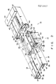
- Track assembly 10 is constituted by selectively combining a plurality of track units. In this transportation system, five types of track units are combined.
- First track unit 16 is a straight track unit for propelling carrier 21 along a straight track.
- Second track unit 17 is a curved track unit for propelling carrier 21 along a curved track.
- Third track unit 18 is a rotary branch unit in which two tracks are perpendicularly branched, and which is used for rotating carrier 21 so as to guide it from one track to the other track.
- Fourth track unit 19 is an orthogonal branch unit in which two tracks are perpendicularly branched and which is used for guiding carrier 21 from one track to the other track without rotating carrier 21.
- Fifth track unit 20 is a curved branch unit in which a curved track is branched from a straight track.
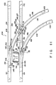
- Stator 40 for a linear induction motor constituting propelling means is provided to first track unit 16. Stator 40 is supported on the lower surfaces of two coupling members 37. Stator 40 is arranged to face reaction plate 58 (to be described later).
- electrical wire 46 is mounted on the side surface of each base member 32.
- Electrical wire 46 includes a power wire, connected to, e.g., inverter 44 and stator 40, for supplying power thereto, and a signal wire connected to first to third sensors 41 to 43, inverter 44, and linear motor controller 45, for transmitting electrical signals.
- a pair of connectors 47 are provided to both ends of electrical wire 46.
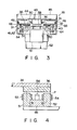
- Carrier 21 comprises flat supporting plate 51 which is located below guide rail 36.
- Four magnetic units 50 are arranged at four corners of supporting plate 51. Magnetic units 50 cause carrier 21 to float from guide rails 36 in a non-contact manner.
- magnetic units 50 are each provided with yokes 51 and 52, facing guide rail 36. Conducting wires are wound around yokes 51 and 52, thus forming coils 53 and 54.
- Air gap P is defined between the top face of each yoke and the lower surface of rail 36.
- Permanent magnet 55 is used to couple yokes 51 and 52 magnetically.
- magnet 55, yokes 51 and 52, gap P, and rail 36 constitute a magnetic circuit.
- Each magnetic unit is further provided with gap sensor 56 for detecting the clearance of gap P.
- Carrier 21 is suspended floating from guide rails 36, in a non-contact manner, by means of a magnetic attractive force acting between magnetic units 50 and guide rail 36.
- units 50 are controlled by zero-power control device, so that the minimum necessary circuit current is supplied to coils 53 and 54 when carrier 21 is made to float.
- four permanent magnets 55 always generate an attractive force equal to the total weight of carrier 21 itself and the load.
- coils 53 and 54 are excited, so as to maintain the air gap clearance at which the attractive force between permanent magnets 55 and rail 36 balances with the total weight of the carrier itself and the load. Coils 53 and 54 serve to subordinately cause carrier 21 to float.
- Control box 57 storing the battery and the zero-power control device is mounted on the upper surface of supporting plate 51.
- Reaction plate 58 constituting a propelling means is mounted at the center of the upper surface of supporting plate 51. Reaction plate 58 faces stator 40. If stator 40 is supplied with current, a traveling magnetic field is generated in stator 40, so that the current is induced to reaction plate 58. Through an interaction between the traveling field and the induced current, reaction plate 58 is subjected to thrust from stator 40, and a propelling force along the guide rail is applied to the carrier.
- hook 61 extends downward from the side edge of supporting plate 51.
- Carrier box 62 for storing a cargo is mounted on the distal end portion of hook 61.
- Wheels 64 are provided to the side edges of supporting plate 51. Wheels 64 are in contact with upper surfaces of corresponding lower flanges 35 of support members 31 when magnetic units 50 do not generate a magnetic attraction force. Wheels 66 are also provided above wheels 64. Wheels 66 are in contact with the lower surfaces of middle flanges 34 of support members 31 when carrier 21 is lifted to its uppermost position.
- Bar code 67 is provided to the side surface of carrier 21. Bar code 67 is located to face first to third sensors 41 to 43. First to third sensors 41 to 43 read bar code 57, so as to detect if the carrier passes the predetermined position, a speed when the carrier passes the predetermined position, and the type of carrier.
- the travel path of the carrier when the travel path of the carrier is modified, a combination of track units are freely changed, so that various travel paths of the carrier can be realized. Thus, the travel path can be easily modified. Furthermore, when one track unit is malfunctioned, the track unit can be replaced with a new one. For this reason, maintenance and inspection of the system can be facilitated.
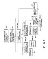
- Local controller 83 performs traffic control of the carriers traveling along branch lines 12 and 13, and supplies an instruction for controlling third station 93 to station controller 85.
- Station controllers 84 and 85 control loader 94 and lifter 95.
- Each station is provided with terminal 86.
- An operator can operate terminal 86 to create the transportation job.
- the speed and position of the carrier are detected by speed sensor 41 and position sensor 42, and the detection signals are supplied to linear motor controller 45.
- Identification sensor 43 identifies the type of carrier, and the detection signal is supplied to local controller 83.
- an auxiliary electrical power source is provided to the system so that power is kept supplied to the transportation system without cutting off power supply to the transportation system.
- the branch unit for transferring the carrier, from the main lines to the branch lines requires a mechanical switching device. Therefore, the branch unit is increased in size, thereby reducing the available space in the factory. Moreover, the switching device is operated mechanically, and especially in the system stated in Japanese Patent Disclosure No. 50-150112, the rollers of the carrier are in contact with the guide plate while the carrier is being transferred. As a result, noise is produced by the transfer apparatus.
- the present inventors thus proposed third track unit or rotary branch unit 18 and fourth track unit or orthogonal branch unit 19 described above.
- a carrier is not in contact with the guide rails, and is transferred from one line to another line without producing noise.
- the size of the branch unit can be reduced.
- a carrier is temporarily stopped at the branch unit, and thereafter, is transferred from one line to another line. For this reason, a relatively long period of time is required in order to transfer the carrier from one line to another line.
- the carrier can reach its destination only after a long period of time.
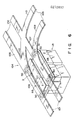
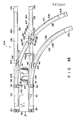
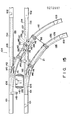
- fifth track unit or curved branch unit 20 The arrangement of fifth track unit or curved branch unit 20 will be described.
- each of first coupling rails 105 and 106 is coupled to the other end of corresponding one of second and third coupling rails 107 to 110.
- forked rail joining sections 111 and 112 at which these coupling rails are joined to each other are defined.
- Each coupling rail is formed of a ferromagnetic material.
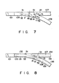
- First and second coupling rails 105 to 108 are linearly formed.
- Third coupling rails 109 and 110 have a predetermined radius of curvature, and are formed to have a curved shape.
- Third coupling rails 109 and 110 intersect the first coupling rails at an obtuse angle.
- An interval between a pair of coupling rails is the same as that between each pair of first to third rails 101 to 103, and is also the same as that between a pair of magnetic units 50.
- stator 116 of the linear induction motor is mounted on support members (not shown).
- Stator 116 is located to face reaction plate 58 of the carrier.
- Stator 116 and reaction plate 58 constitute a means for transferring the carrier from one rail pair to another rail pair.
- the carrier is suspended from the coupling rails in a non-contact manner by an electromagnetic attractive force between magnetic unit 50 and each coupling rail.
- magnetic unit 50 may be subjected to zero-power control described above.
- the carrier is transferred from the first rails to second or third rails (former case), and is transferred from the second or third rails to the first rails (latter case).
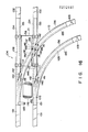
- the carrier coasting by receiving a predetermined propelling force from stator 40, enters from first rails 101 to first coupling rails 105 and 106.
- the carrier travels along the first coupling rails by the predetermined propelling force without being interfered.
- stator 116 biases reaction plate 58 in a direction indicated by arrow D
- the carrier is guided from first coupling rails 105 and 106 to second coupling rails 107 and 108. Thereafter, the carrier keeps traveling by the predetermined propelling force and is guided to second rails 102.
- stator 116 biases reaction plate 58 in a direction indicated by arrow E
- the carrier is guided from the first coupling rails 105 and 106 to third coupling rails 109 and 110. Thereafter, the carrier keeps traveling by the predetermined propelling force and is guided to third rails 103. Therefore, the carrier is transferred to predetermined rails while being suspended from the coupling rails in a non-contact manner without being stopped at the coupling rails.
- First coupling rails 105 and 106 are arranged along the same lines as second coupling rails 107 and 108, and obliquely intersect third coupling rails 109 and 110. In the latter case, the carrier need not receive a transfer force in the direction indicated by arrow D or E, and is automatically guided from the second or third coupling rails to the first coupling rails.
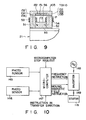
- first to third coupling rails are formed to have a planar shape
- the carrier may often fail to reliably transfer from first rails 101 to third rails 103. The reason will be explained below.
- pairs of first and second ridges 131 to 136 are formed at two sides of each coupling rail.
- First and second ridges 131 and 132 are formed of a ferromagnetic material, and face yokes 51 and 52 of magnetic units 50. More specifically, the width of each of first and second ridges 131 to 136 is substantially the same as that of each of yokes 51 and 52 in the transverse direction of the coupling rail.
- Each ridge is integrally formed on the coupling rail.
- yokes 51 and 52 are moved from the first coupling rail to the third coupling rail along ridges 131 and 132, and are not swung in the transverse direction of the rail. For this reason, the magnetic circuits formed by magnetic units 50 and the coupling rails are not disabled at forked rail joining section 111.
- the carrier can be reliably transferred from first rails 101 to second rails 103.
- fifth track unit or curved branch unit 20 has a shorter transfer time than third track unit or rotary branch unit 18, and the like. A time required until the carrier reaches the destination can be shortened.
- the carrier is transferred in a non-contact manner from the coupling rail. Therefore, no noise is generated. Furthermore, since the transfer means comprises the linear induction motor, the branch unit can be rendered compact. Therefore, a large number of branch units can be provided in a small space in a factory. Traffic control of a large number of carriers can be allowed, and a travel time of each carrier can be shortened.
- ridge intersection 140 at which first ridge 133 of the first coupling rail and second ridge 136 of the third coupling rail intersect each other is formed at each of rail joining sections 111 and 112.
- Figs. 12 and 13 show the section of ridge intersection 140.
- Fig. 12 shows a case wherein magnetic unit 50 is moved toward second coupling rails 107 and 108.
- Fig. 13 shows a case wherein magnetic unit 50 is moved toward third coupling rails 109 and 110.
- two ridges 133 and 136 intersect each other.
- the width of ridge intersection 140 is larger than that of yokes 51 and 52.
- ridge intersection 140 has region C1 which does not face yoke 52.
- region Cl Since the magnetic resistance of region Cl is smaller than the opposite side of ridge intersection 140 region C1, magnetic flux leakage from yoke 52 is flowed in region C1. For this reason, a force for attracting yoke 52 toward region C1 is applied to yoke 52. As a result, yoke 52 is swung.
- ferromagnetic projection 141 is provided to the side surface of each ridge intersection 140.
- yoke 52 receives attractive forces from both region C1 and projection 141. Since the two attractive forces are balanced, yoke 52 can be prevented from being attracted toward only region C1. As a result, swinging motion of yoke 52 can be prevented.
- ridge intersection 140 has region C2 which does not face yoke 51.
- Ferromagnetic projection 142 is provided to the side surface of ridge intersection 140.
- yoke 51 can be prevented from being attracted toward region C2, and can also be prevented from being swung.
- Projection 141 and 142 may be integrally formed on the ridge intersection.
- coupling section 104 has rail intersection 137 at which one second coupling rail 107 and one third coupling rail 110 intersect each other.
- Rail intersection 137 has a plurality of ridge intersections 139 at which first and second ridges 133 and 134 of second coupling rail 107 and first and second ridges 135 and 136 of third coupling rail 110 intersect each other.
- Projections 141 and 142 are provided to the side surface of ridge intersection 139.
- a control apparatus of branch unit 20 will be described hereinafter.
- photo sensor 145 is provided at an end portion of first coupling rail 106 near first rail 101.
- Photo sensor 146 is provided to an end portion of second coupling rail 107 near rail joining section 111.
- These photosensors 145 and 146 emit light toward reaction plate 58 of the carrier, and detect light reflected by plate 58.
- Sensor 145 detects whether or not the carrier enters first coupling rails 105 and 106, and generates a detection signal. More specifically, sensor 145 detects a timing when transfer of the carrier from first rails 101 to second or third rails 102 or 103 is started.
- Sensor 146 detects whether nor not the carrier enters second and third coupling rails 107 to 109, and generates a detection signal. More specifically, sensor 146 detects a timing when transfer of the carrier from first rails 101 to second or third rails 102 or 103 is finished.
- three-phase AC power source 148 is connected to stator 116 through inverter 149.
- the detection signals from sensors 145 and 146 are supplied to microcomputer 147.
- Microcomputer 147 also receives an instruction, supplied from an external apparatus e.g., linear motor controller 45, for transferring the carrier to a predetermined rail, and an instruction for stopping microcomputer 147.
- Microcomputer 147 determines the output frequency of inverter 149 and a propagating direction of a moving magnetic field generated in stator 116 based on these signals and instructions.
- magnetic unit 50 comprises gap sensor 56 for detecting gap P between yokes 53 and 54 and the guide rail.
- grooves 151 are formed in coupling rails 105 to 110 between pairs of ridges 131 to 136. For this reason, gap sensor 56 cannot accurately detect the gap between ridges 131 to 136 and yokes 51 and 52.
- non-magnetic member 152 is stored in each groove 151.
- the top face of non-magnetic member 152 is located on the identical plane to the top face of the ridge. Therefore, gap sensor 56 emits light toward the top face of non-magnetic member 152, and detects light reflected by the top face.
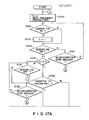
- sensors 145 and 146 are always operated. More specifically, when the carrier is not located at coupling section 104, the flow is looped in steps 102, 104, and 121.
- step 106 It is checked in step 106 whether the carrier is transferred to second or third rails 102 or 103. If the carrier is transferred to third rails 103, inverter 149 receives an instruction of a moving magnetic field in a direction indicated by arrow E and a predetermined frequency instruction in step 108. Then, the carrier traveling along the first coupling rails receives a transfer force toward the third coupling rails, and transfer of the carrier is started.
- step 109 When the carrier is transferred by a predetermined distance, sensor 145 is turned off in step 109. If the carrier is further transferred by the predetermined distance, sensor 146 is turned on in step 110. Thereafter, when the carrier has reached a position shown in Fig. 15, sensor 146 is turned off in step 111. Thus, transfer of the carrier from first rails 101 to third rails 103 is ended. Flow returns to step 101, so that inverter 149 receives a zero-frequency instruction and the energization of stator 116 is stopped. The carrier keeps traveling along third rails 103. Until subsequent carrier reaches first coupling rails 105 to 110, the flow is looped in steps 102, 104, and 121.
- inverter 149 receives an instruction of a moving magnetic field in a direction indicated by arrow D and a predetermined frequency instruction in step 107. Other operations are the same as those when the carrier is transferred to third rails 103. When the carrier has reached a position shown in Fig. 16, energization of stator 116 is stopped.
- a first microcomputer stop request which is supplied to prevent stator 116 from being energized at, for instance, trial traveling, is detected in steps 121 and 132, the flow jumps to an end. If a second microcomputer stop request, which is supplied to immediately stop the energization of stator 116 in emergency, is detected in steps 112, 141 and 152, the flow advances to step 113, a zero-frequency instruction is supplied to inverter 149, and the energization of stator 116 is stopped.
- each coupling rail As described above, a pair of ridges facing a pair of yokes are formed on each coupling rail. For this reason, magnetic flux leakage of each yoke is concentrated on only the ridge, and is not biased to other portions. Thus, a force for preventing the yoke from being shifted toward the transverse direction of the rail can be generated. The yoke is moved along the ridge, and swinging motion of the yoke can be prevented. Therefore, the magnetic circuit between the magnetic unit and the coupling rail cannot be disabled. The carrier can be reliably transferred from one line to another line, and cannot be dropped.
- fifth track unit or curved branch unit 20 has a shorter transfer time than third track unit or rotary branch unit 18. Therefore, a time required until the carrier reaches the destination can be shortened.
- the carrier is transferred in a non-contact manner, and hence, no noise is generated. Since the transfer means comprises the linear induction motor, the branch unit can be rendered compact. A large number of branch units can be provided to the track even in a small space in a factory. A large number of carriers can thus be subjected to traffic control, and a travel time of each carrier can be shortened.
- each second coupling rail 102 is linearly formed.
- second coupling rail 102 may be formed to have a curved shape.
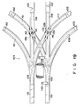
- coupling section 104 may be coupled to four track units.
- the carrier can be transferred from first rails 101 to fourth coupling rails 161 and then fourth rails 162 by the same transfer means of above embodiment.
- the branch unit may alternatively be designed so as to transfer carrier 21 by utilizing air pressure.
- air nozzles 163 may be arranged so that they can blow air against carrier 21, thereby transferring the carrier from first coupling rail to second or third coupling rail.
- the number of yokes is not limited to two but may be three or more. If three or more yokes are arranged, each coupling rail need only have ridges corresponding in number to the yokes.
Landscapes
- Engineering & Computer Science (AREA)
- Mechanical Engineering (AREA)
- Physics & Mathematics (AREA)
- Electromagnetism (AREA)
- Power Engineering (AREA)
- Transportation (AREA)
- Architecture (AREA)
- Civil Engineering (AREA)
- Structural Engineering (AREA)
- Control Of Vehicles With Linear Motors And Vehicles That Are Magnetically Levitated (AREA)
- Non-Mechanical Conveyors (AREA)
Priority Applications (1)
| Application Number | Priority Date | Filing Date | Title |
|---|---|---|---|
| EP91202887A EP0474321B1 (de) | 1986-12-19 | 1987-12-18 | Transportsystem mit schwebendem Lastträger |
Applications Claiming Priority (2)
| Application Number | Priority Date | Filing Date | Title |
|---|---|---|---|
| JP61303442A JP2501808B2 (ja) | 1986-12-19 | 1986-12-19 | 磁気浮上式搬送システム |
| JP303442/86 | 1986-12-19 |
Related Child Applications (1)
| Application Number | Title | Priority Date | Filing Date |
|---|---|---|---|
| EP91202887.5 Division-Into | 1987-12-18 |
Publications (3)
| Publication Number | Publication Date |
|---|---|
| EP0272897A2 true EP0272897A2 (de) | 1988-06-29 |
| EP0272897A3 EP0272897A3 (en) | 1989-05-24 |
| EP0272897B1 EP0272897B1 (de) | 1993-11-10 |
Family
ID=17921046
Family Applications (2)
| Application Number | Title | Priority Date | Filing Date |
|---|---|---|---|
| EP87311213A Expired - Lifetime EP0272897B1 (de) | 1986-12-19 | 1987-12-18 | Transportsystem vom Typ eines schwebenden Trägers |
| EP91202887A Expired - Lifetime EP0474321B1 (de) | 1986-12-19 | 1987-12-18 | Transportsystem mit schwebendem Lastträger |
Family Applications After (1)
| Application Number | Title | Priority Date | Filing Date |
|---|---|---|---|
| EP91202887A Expired - Lifetime EP0474321B1 (de) | 1986-12-19 | 1987-12-18 | Transportsystem mit schwebendem Lastträger |
Country Status (5)
| Country | Link |
|---|---|
| US (2) | US4882999A (de) |
| EP (2) | EP0272897B1 (de) |
| JP (1) | JP2501808B2 (de) |
| KR (1) | KR910002780B1 (de) |
| DE (2) | DE3751208T2 (de) |
Cited By (6)
| Publication number | Priority date | Publication date | Assignee | Title |
|---|---|---|---|---|
| WO1990008086A1 (de) * | 1989-01-10 | 1990-07-26 | Magnet Motor Gesellschaft Für Magnetmotorische Technik Mbh | Automatische guttransportvorrichtung mit linearmotorgetriebenen transportelementen |
| FR2738005A1 (fr) * | 1995-08-22 | 1997-02-28 | Flix Jean Marie | Dispositif permettant d'espacer des produits ou des lots de produits |
| EP1316504A1 (de) * | 2001-11-29 | 2003-06-04 | ABB PATENT GmbH | Gepäcktransportsystem über lange Distanzen |
| EP3176111A1 (de) * | 2015-12-04 | 2017-06-07 | BEUMER GmbH & Co. KG | Sortiervorrichtung für stückgut und verfahren |
| CN113944691A (zh) * | 2021-09-22 | 2022-01-18 | 哈尔滨工业大学 | 移动式气浮导向机构 |
| CN116494772A (zh) * | 2023-05-25 | 2023-07-28 | 湖南根轨迹智能科技有限公司 | 一种悬浮间隙调整保护装置、磁悬浮系统及方法 |
Families Citing this family (34)
| Publication number | Priority date | Publication date | Assignee | Title |
|---|---|---|---|---|
| JPS6416101U (de) * | 1987-07-17 | 1989-01-26 | ||
| US5170714A (en) * | 1988-06-13 | 1992-12-15 | Asahi Glass Company, Ltd. | Vacuum processing apparatus and transportation system thereof |
| US5049218A (en) * | 1989-12-04 | 1991-09-17 | Geoffrey Martin | Magnetic support & transport system |
| US5228820A (en) * | 1990-09-21 | 1993-07-20 | Advanced Technology And Research Corporation | Article handling system with distributed storage |
| DE4127879C2 (de) * | 1991-08-22 | 1994-07-07 | Mtu Muenchen Gmbh | Regelvorrichtung zur Regelung von Luftspalten elektromagnetischer Tragsysteme |
| US5281558A (en) * | 1992-11-02 | 1994-01-25 | Cadence Design Systems, Inc. | Cloning method and system for hierarchical compaction |
| DE4413899A1 (de) * | 1994-04-21 | 1995-10-26 | Magnetbahn Gmbh | Linearmotorfahrzeug mit permanentelektromagnetischer Regelung |
| US6182576B1 (en) | 1996-05-07 | 2001-02-06 | Einar Svensson | Monorail system |
| US5845581A (en) * | 1996-05-07 | 1998-12-08 | Svensson; Einar | Monorail system |
| US6450103B2 (en) | 1996-05-07 | 2002-09-17 | Einar Svensson | Monorail system |
| DE19725644A1 (de) * | 1997-06-18 | 1998-12-24 | Alsthom Cge Alcatel | Bahn für mittels Weichen verzweigte Schienenstränge |
| TWI290272B (en) * | 2004-03-12 | 2007-11-21 | Murata Machinery Ltd | Moving body system |
| US7448012B1 (en) | 2004-04-21 | 2008-11-04 | Qi-De Qian | Methods and system for improving integrated circuit layout |
| JP4148194B2 (ja) * | 2004-07-22 | 2008-09-10 | 村田機械株式会社 | 搬送台車システム |
| KR20070054683A (ko) * | 2004-08-23 | 2007-05-29 | 브룩스 오토메이션 인코퍼레이티드 | 승강기 기반의 도구 적재 및 버퍼링 시스템 |
| US7677180B2 (en) * | 2005-06-09 | 2010-03-16 | International Business Machines Corporation | Apparatus and method for steering transport vehicles in semiconductor processing |
| KR100675314B1 (ko) * | 2005-12-30 | 2007-01-29 | 한국기계연구원 | 자기부상 열차용 분기기의 이송장치 |
| US7757609B2 (en) * | 2006-10-10 | 2010-07-20 | Launchpoint Technologies, Inc. | Track switching for a magnetically levitated transportation system and method |
| KR100913795B1 (ko) * | 2007-11-30 | 2009-08-31 | 성삼경 | 자기부상열차 |
| JP5217623B2 (ja) * | 2008-05-19 | 2013-06-19 | 株式会社安川電機 | 磁気浮上制御装置 |
| KR101974185B1 (ko) * | 2012-06-25 | 2019-04-30 | 세메스 주식회사 | 자기 부상 이송 장치 및 방법 |
| US9228298B2 (en) * | 2013-03-14 | 2016-01-05 | Daryl Oster | Evacuated tube transport system with interchange capability |
| CN106087622B (zh) * | 2016-07-22 | 2018-01-09 | 株洲时代电子技术有限公司 | 基于磁力固定的标志点装置 |
| DE102016224951A1 (de) * | 2016-12-14 | 2018-06-14 | Robert Bosch Gmbh | Beförderungsvorrichtung mit einem Stator zur kontrollierten Beförderung eines Transportkörpers relativ zum Stator |
| CN108638914B (zh) * | 2018-07-04 | 2021-08-17 | 中车株洲电力机车有限公司 | 一种吊挂式磁浮交通系统及其磁浮列车悬浮架 |
| CN109081059B (zh) * | 2018-09-28 | 2023-12-01 | 德瑞精工(深圳)有限公司 | 一种搬运装置及工作件变轨方法 |
| CN109399218A (zh) * | 2018-11-21 | 2019-03-01 | 中铁第四勘察设计院集团有限公司 | 一种冷链物流管道系统循环式连续收发系统及方法 |
| JP7300281B2 (ja) * | 2019-03-08 | 2023-06-29 | 株式会社日立ハイテク | 搬送装置、およびそれを備えた検体分析システム、検体前処理装置、ならびに被搬送体の搬送方法 |
| JP7410615B2 (ja) * | 2019-09-03 | 2024-01-10 | キヤノン株式会社 | 加工システム、および物品の製造方法 |
| US12448224B2 (en) * | 2020-12-11 | 2025-10-21 | Laitram, L.L.C. | Conveyor transfer system |
| US20220363137A1 (en) * | 2021-05-11 | 2022-11-17 | NEXTFIRST Engineering Technologies Private Limited | System for wireless power transfer to a mobile robot |
| US12559206B2 (en) * | 2023-03-30 | 2026-02-24 | Bec Companies, Inc. | Storage and distribution system for containers |
| WO2025096729A1 (en) * | 2023-10-31 | 2025-05-08 | Brooks Automation Us, Llc | Scalable substrate handler apparatus and processing apparatus including the same |
| CN117602312B (zh) * | 2024-01-02 | 2024-12-06 | 苏州曼凯系统集成科技有限公司 | 一种物流车间吊顶轨道系统 |
Family Cites Families (17)
| Publication number | Priority date | Publication date | Assignee | Title |
|---|---|---|---|---|
| DE1194745B (de) * | 1959-01-17 | 1965-06-10 | Adolf Opfermann Dipl Chem | Gleisstueck fuer Spielzeug- und Modell-eisenbahnen mit elektrischen Zusatzleitern |
| BE741218A (de) * | 1968-11-15 | 1970-04-16 | ||
| US3570177A (en) * | 1970-01-29 | 1971-03-16 | Remco Ind Inc | Toy monorail train system |
| US3736880A (en) * | 1971-04-19 | 1973-06-05 | Rohr Industries Inc | Feedback control circuit for magnetic suspension and propulsion system |
| US3937148A (en) * | 1973-01-02 | 1976-02-10 | Cambridge Thermionic Corporation | Virtually zero power linear magnetic bearing |
| CA1044774A (en) * | 1974-07-26 | 1978-12-19 | Gotz Heidelberg | Magnetic system for supporting and propelling a vehicle along a roadway |
| US4109584A (en) * | 1976-12-22 | 1978-08-29 | Japan Airlines Co., Limited | Track switching device for two-rail type tracks |
| DE2939540A1 (de) * | 1979-09-28 | 1981-04-02 | Siemens AG, 1000 Berlin und 8000 München | Weiche fuer eine schwebebahn mit elektromagnetischer fuehrungseinrichtung |
| JPS619104A (ja) * | 1984-06-20 | 1986-01-16 | Fuji Electric Co Ltd | 磁気浮上搬送装置 |
| EP0179188B1 (de) * | 1984-10-23 | 1990-07-25 | Kabushiki Kaisha Toshiba | Transportsystem vom Typ mit schwebendem Träger |
| JP2680296B2 (ja) * | 1985-03-29 | 1997-11-19 | 株式会社東芝 | 浮上式搬送装置 |
| JPH06101884B2 (ja) * | 1985-03-29 | 1994-12-12 | 株式会社東芝 | 浮上式搬送装置 |
| JPH0687603B2 (ja) * | 1986-03-27 | 1994-11-02 | 株式会社東芝 | 浮上式搬送装置 |
| JP2609588B2 (ja) * | 1986-05-14 | 1997-05-14 | 株式会社東芝 | 浮上式搬送装置 |
| JP2732562B2 (ja) * | 1986-05-14 | 1998-03-30 | 株式会社東芝 | 浮上式搬送装置 |
| US4678981A (en) * | 1986-08-01 | 1987-07-07 | Spacesaver Corporation | Portable power source for mobile storage carriage |
| US4718621A (en) * | 1986-10-24 | 1988-01-12 | Shinko Electric Co., Ltd. | Automatic transportation system |
-
1986
- 1986-12-19 JP JP61303442A patent/JP2501808B2/ja not_active Expired - Lifetime
-
1987
- 1987-12-05 KR KR1019870014416A patent/KR910002780B1/ko not_active Expired
- 1987-12-18 US US07/135,084 patent/US4882999A/en not_active Expired - Lifetime
- 1987-12-18 DE DE3751208T patent/DE3751208T2/de not_active Expired - Fee Related
- 1987-12-18 EP EP87311213A patent/EP0272897B1/de not_active Expired - Lifetime
- 1987-12-18 DE DE87311213T patent/DE3788115T2/de not_active Expired - Fee Related
- 1987-12-18 EP EP91202887A patent/EP0474321B1/de not_active Expired - Lifetime
-
1989
- 1989-02-02 US US07/305,191 patent/US4934279A/en not_active Expired - Fee Related
Cited By (8)
| Publication number | Priority date | Publication date | Assignee | Title |
|---|---|---|---|---|
| WO1990008086A1 (de) * | 1989-01-10 | 1990-07-26 | Magnet Motor Gesellschaft Für Magnetmotorische Technik Mbh | Automatische guttransportvorrichtung mit linearmotorgetriebenen transportelementen |
| FR2738005A1 (fr) * | 1995-08-22 | 1997-02-28 | Flix Jean Marie | Dispositif permettant d'espacer des produits ou des lots de produits |
| EP0761573A1 (de) * | 1995-08-22 | 1997-03-12 | Jean-Marie Flix | Vorrichtung zum Einstellen der Zwischenräume bei Transportgütern oder Gruppen von Gütern |
| EP1316504A1 (de) * | 2001-11-29 | 2003-06-04 | ABB PATENT GmbH | Gepäcktransportsystem über lange Distanzen |
| EP3176111A1 (de) * | 2015-12-04 | 2017-06-07 | BEUMER GmbH & Co. KG | Sortiervorrichtung für stückgut und verfahren |
| US9873573B2 (en) | 2015-12-04 | 2018-01-23 | Beumer Gmbh & Co. Kg | Sorting device for piece goods and method |
| CN113944691A (zh) * | 2021-09-22 | 2022-01-18 | 哈尔滨工业大学 | 移动式气浮导向机构 |
| CN116494772A (zh) * | 2023-05-25 | 2023-07-28 | 湖南根轨迹智能科技有限公司 | 一种悬浮间隙调整保护装置、磁悬浮系统及方法 |
Also Published As
| Publication number | Publication date |
|---|---|
| EP0272897B1 (de) | 1993-11-10 |
| JP2501808B2 (ja) | 1996-05-29 |
| US4882999A (en) | 1989-11-28 |
| EP0474321A2 (de) | 1992-03-11 |
| KR910002780B1 (ko) | 1991-05-04 |
| US4934279A (en) | 1990-06-19 |
| EP0474321A3 (en) | 1992-04-15 |
| DE3751208D1 (de) | 1995-05-04 |
| DE3788115D1 (de) | 1993-12-16 |
| DE3751208T2 (de) | 1995-08-24 |
| EP0272897A3 (en) | 1989-05-24 |
| KR880007292A (ko) | 1988-08-26 |
| EP0474321B1 (de) | 1995-03-29 |
| DE3788115T2 (de) | 1994-05-05 |
| JPS63157602A (ja) | 1988-06-30 |
Similar Documents
| Publication | Publication Date | Title |
|---|---|---|
| US4934279A (en) | Transportation system of a floated-carrier type | |
| US5156093A (en) | Transportation system of floated-carrier type | |
| EP0246096B1 (de) | Transportsystem mit schwebendem Lastträger | |
| EP0288615A2 (de) | Transportsystem vom Typ eines schwebenden Trägers | |
| JP3327367B2 (ja) | 搬送設備 | |
| US4729323A (en) | Transportation system of a floated-carrier type | |
| JP3109737B2 (ja) | 浮上式搬送装置 | |
| JPS627305A (ja) | 浮上式搬送装置 | |
| JP2976504B2 (ja) | 磁気浮上式搬送装置 | |
| JP2634044B2 (ja) | 磁気浮上式搬送装置 | |
| JPH11215614A (ja) | 浮上式搬送装置 | |
| JP2563912B2 (ja) | 浮上式搬送装置 | |
| JPH06101884B2 (ja) | 浮上式搬送装置 | |
| JPH04117111A (ja) | 磁気浮上式搬送装置 | |
| JPH0669852B2 (ja) | 浮上式搬送装置 | |
| JPH04117112A (ja) | 磁気浮上式搬送装置 | |
| JPS6369402A (ja) | 搬送装置 | |
| JPS61170206A (ja) | 輝上式搬送装置 | |
| JPS62185503A (ja) | 浮上式搬送装置 | |
| DUST | T. Yokoyama¹, T. Azukizawa2, G. Iketani, S. Koguchi, T. Azima, H. Kawai | |
| JPH0458247B2 (de) | ||
| JPS61132003A (ja) | 浮上式搬送装置 | |
| JPH04208008A (ja) | 磁気浮上搬送装置の異常時のビークル復帰方法 | |
| JPH03164005A (ja) | 磁気浮上搬送装置 | |
| JPS62125409A (ja) | 搬送装置における移動体の位置決め装置 |
Legal Events
| Date | Code | Title | Description |
|---|---|---|---|
| PUAI | Public reference made under article 153(3) epc to a published international application that has entered the european phase |
Free format text: ORIGINAL CODE: 0009012 |
|
| 17P | Request for examination filed |
Effective date: 19880208 |
|
| AK | Designated contracting states |
Kind code of ref document: A2 Designated state(s): DE FR GB |
|
| PUAL | Search report despatched |
Free format text: ORIGINAL CODE: 0009013 |
|
| AK | Designated contracting states |
Kind code of ref document: A3 Designated state(s): DE FR GB |
|
| 17Q | First examination report despatched |
Effective date: 19910709 |
|
| GRAA | (expected) grant |
Free format text: ORIGINAL CODE: 0009210 |
|
| AK | Designated contracting states |
Kind code of ref document: B1 Designated state(s): DE FR GB |
|
| REF | Corresponds to: |
Ref document number: 3788115 Country of ref document: DE Date of ref document: 19931216 |
|
| ET | Fr: translation filed | ||
| PLBE | No opposition filed within time limit |
Free format text: ORIGINAL CODE: 0009261 |
|
| STAA | Information on the status of an ep patent application or granted ep patent |
Free format text: STATUS: NO OPPOSITION FILED WITHIN TIME LIMIT |
|
| 26N | No opposition filed | ||
| PGFP | Annual fee paid to national office [announced via postgrant information from national office to epo] |
Ref country code: GB Payment date: 19971209 Year of fee payment: 11 Ref country code: FR Payment date: 19971209 Year of fee payment: 11 |
|
| PGFP | Annual fee paid to national office [announced via postgrant information from national office to epo] |
Ref country code: DE Payment date: 19971230 Year of fee payment: 11 |
|
| PG25 | Lapsed in a contracting state [announced via postgrant information from national office to epo] |
Ref country code: GB Free format text: LAPSE BECAUSE OF NON-PAYMENT OF DUE FEES Effective date: 19981218 |
|
| GBPC | Gb: european patent ceased through non-payment of renewal fee |
Effective date: 19981218 |
|
| PG25 | Lapsed in a contracting state [announced via postgrant information from national office to epo] |
Ref country code: FR Free format text: LAPSE BECAUSE OF NON-PAYMENT OF DUE FEES Effective date: 19990831 |
|
| REG | Reference to a national code |
Ref country code: FR Ref legal event code: ST |
|
| PG25 | Lapsed in a contracting state [announced via postgrant information from national office to epo] |
Ref country code: DE Free format text: LAPSE BECAUSE OF NON-PAYMENT OF DUE FEES Effective date: 19991001 |