EP0272911A2 - Datengeschwindigkeitsbegrenzer für optisches Übertragungssystem - Google Patents
Datengeschwindigkeitsbegrenzer für optisches Übertragungssystem Download PDFInfo
- Publication number
- EP0272911A2 EP0272911A2 EP87311276A EP87311276A EP0272911A2 EP 0272911 A2 EP0272911 A2 EP 0272911A2 EP 87311276 A EP87311276 A EP 87311276A EP 87311276 A EP87311276 A EP 87311276A EP 0272911 A2 EP0272911 A2 EP 0272911A2
- Authority
- EP
- European Patent Office
- Prior art keywords
- fiber
- mode
- multimode
- pulse
- modes
- Prior art date
- Legal status (The legal status is an assumption and is not a legal conclusion. Google has not performed a legal analysis and makes no representation as to the accuracy of the status listed.)
- Withdrawn
Links
Images


Classifications
-
- H—ELECTRICITY
- H04—ELECTRIC COMMUNICATION TECHNIQUE
- H04B—TRANSMISSION
- H04B10/00—Transmission systems employing electromagnetic waves other than radio-waves, e.g. infrared, visible or ultraviolet light, or employing corpuscular radiation, e.g. quantum communication
- H04B10/25—Arrangements specific to fibre transmission
- H04B10/2581—Multimode transmission
Definitions
- the present invention relates to optical fiber transmission systems and more particularly to a device for introducing dispersion into such a system to limit its bandwidth or information carrying capacity.
- an optical transmission system It is sometimes desirable to limit the capacity of an optical transmission system to some predetermined maximum data rate.
- a customer may purchase the sole use of a single-mode optical fiber transmission line and connect its own terminal equipment thereto.
- the price of using the transmission line may be based on the maximum data rate that the customer intends to transmit.
- the bandwidth of the single-mode fiber transmission line may be much greater than that currently needed by the customer.
- the bandwidth of such a system can be limited by inserting a suitable device in series with the transmission medium.
- the device should possess some or all of the following attributes. It should not degrade the performance of the system at bit rates up to the set limit of the agreed upon bit rate.
- the insertion loss should be as small as possible.
- the device should be relatively insensitive to system length and wavelength. In addition, it should be simple and inexpensive to make and use.
- Some proposed active devices include those which monitor the bit rate and render the system inoperable if the bit rate exceeds the maximum permissible rate. These active devices are complex and expensive.
- Two relatively simple passive devices employ power splitters that branch off a portion of the bit power and reintroduce it with a predetermined delay.
- the splitter technique suffers from the disadvantage of wavelength dependence. Also, repeated coupling of progressively smaller amplitude pulses induced by the splitter at multiples of the primary delay time, may cause problems.
- a passive data rate limiter is disclosed in European Patent Application No. 87307021.3 filed August 7, 1987 for "Data Rate Limiter for Optical Transmission System.”
- the transmitted signal is connected to wavelength disperser means which spatially separates the different wavelength components of the transmitted signal.
- Each wavelength component is then propagated with a different delay by optical fiber delay means.
- the wavelength component which propagates with the least delay through the transmission optical fiber is subjected to the least induced delay in the optical fiber delay means and that which propagates with the greatest delay through the transmission optical fiber is subjected to the greatest induced delay in optical fiber delay means, the remaining components being subjected to intermediate delays.
- the delayed wavelength components are combined to form a series of broadened optical pulses. That device lacks simplicity and is wavelength dependent.
- the bandwidth limiter of the present invention comprises a multimode optical fiber for propagating a plurality of modes at different velocities, and means for receiving input light.
- First transition means is located at the first end of the multimode fiber for redistributing energy received by the receiving means and initiating in the multimode fiber the propagation of a plurality of modes which propagate therethrough at different velocities.
- the reception by the receiving means of a given pulse of light energy having a given width results in the arrival at the second end of the multimode fiber of a plurality of modes, the summation of which would be a light pulse having a width which is greater than the given width by a time interval that is equal to the differential delay time between the slowest and the fastest propagating modes in the multimode fiber.
- Second transition means can be located at the second end of the multimode fiber for converting a portion of the energy in each mode that propagates in the multimode fiber, except the LP01 mode, into at least one lower order mode.
- the means for receiving input light is an optical fiber that is capable of transmitting fewer modes than the multimode optical fiber.
- This input optical fiber is preferably a single-mode fiber.
- the mode converter for the present invention can be formed by providing an optical fiber comprising two adjacent sections. The junction between the two sections is heated and the sections are bent at the junction so that the longitudinal axis of one of the fiber sections is angularly offset with respect to the other fiber section.
- the method can also comprise the step of laterally moving the longitudinal axes of the fiber sections with respect to each other.
- the method can further comprise the steps of connecting a source of light pulses to one of the fiber sections and monitoring the light pulses emitted from the remaining fiber section.
- the step of bending is continued until the step of monitoring reveals that the power levels of at least two modes propagating in one of the fiber sections are at a predetermined ratio.
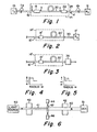
- Optical fiber transmission line sections 11a and 11b of FIG. 1 are representative of such a fiber.
- sections 11a and 11b are connected by a fusion joint, a connector or a signal repeater.
- many other optical transmission line sections may be connected serially with sections 11a and 11b in order to interconnect two remote stations.
- the customer may initially intend to connect to the ends of the optical transmission line a particular transmitter 10 and a particular receiver 12. With such terminal equipment, the customer may presently have the capability of transmitting data at a predetermined maximum data rate and may desire to be billed at a rate which depends upon that predetermined maximum data rate.
- the optical fiber transmission line may be a fiber having a bandwidth capable of transmitting information at a rate much greater than the predetermined maximum rate.
- Examples of high bandwidth fibers are single-mode, few mode and graded index multimode fibers. Since the terminal equipment is under the control of the customer, that terminal equipment could be upgraded by the customer so that the system would transmit information at a rate greater than the predetermined rate. However, if the telephone company had no knowledge of the change in terminal equipment, the customer could transmit information over the fiber at the higher rate while continuing to pay the lower price for using the fiber.
- Bandwidth limiting device 14 of FIG. 1 can be employed to effect such a result.
- Device 14 comprises an input optical fiber 16, a mode converter 18 and a multimode bandwidth limiter fiber 20. If the output of device 14 is to be connected to a fiber 11b which propagates fewer modes than fiber 20, a second mode converter 22 and an output optical fiber 24 are employed.
- Fibers 16 and 24 should be selected to be compatable with transmission fibers 11a and 11b.
- Fibers 16 and 24 may be single-mode fibers if fibers 11a and 11b are single-mode fibers. However, some other design criteria may be paramount. For example, it may be advantageous to form fiber 16 from an end region of fiber 20. An example of such a design is described below.
- the function of the input and output mode converters is to (1) initiate in an optical fiber the propagation of a number of modes which is greater than the number of modes which an input signal would otherwise induce in such fiber or (2) redistribute the power propagating in a given number of modes.
- the output mode converter is not needed in the embodiments of FIGS. 2 and 3, wherein elements similar to those of FIG. 1 are represented by primed reference numerals.
- the output endface of multimode fiber 20 ⁇ is directly connected to a multimode fiber 30 having a mode volume equal to or greater than that of fiber 20 ⁇ .
- the output of multimode fiber 20 ⁇ is directly connected to a photo detector 36 which converts the modes propagating in fiber 20 ⁇ into an electrical signal.
- FIGS. 2 and 3 have the following disadvantages as compared with that of FIG. 1. If the length of multimode fiber 30 of FIG. 2 is appreciable, it will introduce dispersion into the system which will limit the bit rate to which the system can eventually be upgraded. In the embodiment of FIG. 3, the device 14 ⁇ must be located at the output end of the optical transmission system where it may be under the control of the customer.
- Multimode fiber 20 should be one wherein the differential mode delay between the highest and lowest order modes propagating therein is relatively great.
- Two of the many possible suitable fibers are a step-index fiber (FIG. 4) and a multi-core fiber (FIG. 5).
- the meridional mode which propagates at low angles along the axis of a step-index fiber experiences less delay than a skew ray which does not. Since the skew ray continually reflects from the core-clad interface, its delay time in the multimode fiber is greater than that of the meridional ray.
- a multi-core fiber can comprise a central core and one or more concentric light-propagating regions which are optically isolated from one another by annular cladding regions.
- the propagation characteristics of the different cores can be made sufficiently different that light propagating in each of the core regions of the fiber experiences a different delay.
- mode converters which may be employed in the devices of FIGS. 1, 2 and 3 are (1) lateral and angular misalignment between two fiber sections (2) a short tapered region between two fibers that are laterally and angularly misaligned, (3) a tapered fiber, (4) a spherical ball lens, and (5) periodic perturbation.
- Type (1) can consist of two different fibers spliced together or a single piece of multimode fiber having a sharp bend or kink therein. Discussed below are various methods for making type (1), type (2) mode and type (5) converters.
- FIGS. 6 and 7 illustrate a method of making the above-listed type (2) mode converter. These figures schematically illustrate a top view of a fiber splicing apparatus similar to that disclosed in U.S. Patent No. 4,049,414. It is assumed in this example that device 14 of FIG. 1 will be utilized in an optical transmission system that is to be operated at a bit rate of 90 Mb/sec. A differential delay of 4.5 ns is therefore required.
- a section 40 of step index two-mode fiber is cut to a length of 2.8 km that is sufficient to provide the desired differential mode delay.
- a single-mode step index fiber is cut to a length 41 suitable for coupling purposes, eg. about 1-2 m.
- the outer diameters of fibers 40 and 41 are 210 ⁇ m and 125 ⁇ m, respectively, and their core diameters are 15 ⁇ m and 9 ⁇ m, respectively.
- Both fibers have GeO2-doped SiO2 cores and SiO2 cladding.
- the cores contain a sufficient amount of GeO2 to provide a ⁇ of 0.3%.
- Fibers 40 and 41 are secured near their ends to x-y-z positioners 42 and 43, respectively, by vacuum chucks. Positioners 42 and 43 are manipulated to position fibers 40 and 41 in axial alignment, their abutting endfaces being about midway between electrodes 44 and 46.
- a source 50 of short optical pulses which is connected to input fiber 41, initiates therein the propagation of a single-mode (LP01) signal. This signal is coupled to and propagates through multimode fiber 40 to detector/oscilloscope 51. The train of short optical pulses appears on the oscilloscope as pulse 54 of FIG. 8.
- Axial alignment of fibers 40 and 41 can be ascertained by observing peak power propagation between the fibers, i.e. by maximizing the amplitude of pulse 54. One of the fibers is then laterally offset about 5 ⁇ m with respect to the other.
- An arc 47 is generated between electrodes 44 and 46 to fuse the adjacent endfaces in a known manner. Both of the positioners are moved about 100 ⁇ m away from the plane of electrodes 44 and 46 to form a short tapered region 48, which is shown in FIG. 7. It is noted that this taper would not be necessary if fibers 40 and 41 had the same outside diameter. At this stage of the process, the almost unperceptible blip 55 is evidence of the occurrence of a very small amount of coupling to the LP11 mode at taper 48 where the fiber axes are laterally offset. The differential delay between the propagation of the LP01 and LP11 modes through fiber 40 causes blip 55 to appear at the right of pulse 54.
- Positioners 42 and 43 are moved laterally in direction 52 until tapered region 48 contacts electrode 46. Electrodes 44 and 46 are again energized, and the resultant arc 47 softens tapered region 48. Positioner 43 is then slowly moved in direction 52 to form a sharp bend at tapered region 48. While positioner 43 is being moved in this manner, the output signal is observed on oscilloscope 51. As the bend angle ⁇ increases, blip 55 begins to increase in amplitude, and the previously large amplitude LP01 pulse 54 begins to decrease in amplitude.
- the amplitude of the delayed LP11 pulse is about 70% of the amplitude of the LP01 pulse.
- the composite of fibers 40 and 41 remains sharply bent at the angle ⁇ i that is necessary to achieve that mode conversion which results in a 0.7 pulse amplitude ratio between the LP11 and LP01 modes.
- the angle ⁇ i is about 3° for such a pulse amplitude ratio.
- moving fiber 41 in direction 52 can cause it to move laterally as well as angularly with respect to fiber 40. If this lateral movement is too great, the power coupled to the LP01 and LP11 modes decreases to less than 50% and 35%, respectively. Care must therefore be taken when performing this step.
- a 1-2 m section of single-mode fiber is butted against that end in the manner described in conjunction with FIG. 6.
- the detector/oscilloscope is connected to the output end of the single-mode fiber.
- the LP01 signal propagating in multimode fiber 40 also propagates in the single-mode output fiber, thereby generating on the oscilloscope a pulse similar to pulse 54 of FIG. 8.
- Axial alignment of the fibers is indicated by maximizing this pulse.
- One of the fibers is laterally offset about 5 ⁇ m, and the electrodes are energized to fuse the fiber endfaces. The lateral offset causes a blip similar to blip 55 to appear.
- This blip is indicative of a minute amount of mode conversion of the LP11 mode propagating in fiber 40 to the LP01 mode. Since the LP11 mode is delayed with respect to the LP01 mode in fiber 40, the blip appears to the right of the larger pulse. After the fused junction is elongated to form a tapered region a few hundred ⁇ m long, the tapered region is brought into contact with electrode 46. The single-mode fiber is moved laterally such that it forms an angle ⁇ with respect to the multimode fiber. As the angle ⁇ increases, a greater portion of the LP11 mode propagating in fiber 40 converts to the LP01 mode and propagates in the single-mode output fiber, and some of the LP01 mode converts to the LP11 mode. As shown in FIG. 10, the amplitude of the large pulse 61 has decreased and the amplitude of the blip has increased to that of pulse 60.
- the amplitude of the delayed output pulse 60 is about 50% of the amplitude of the first occurring output pulse 61.
- lateral movement of the single-mode fiber ceases.
- the output single-mode fiber and multimode fiber 40 remain bent at an angle ⁇ o which is also about 3°.
- the resultant device is suitable for use as device 14 in FIG. 1.
- the lateral and angular offsets between the fibers have optimal values which depend upon the particular fibers employed and upon the desired power ratio of the modes generated at the mode converter.
- Mode conversion can also be implemented in the multimode limiter fiber itself.
- the required length of multimode limiter fiber for providing the differential mode delays is determined, and a length of such fiber equal to the predetermined length plus about two meters is obtained.
- One meter at each end will function as the input and output fiber.
- a sharp bend is formed one meter from each end in the manner described in Example 1 to form bends having angles ⁇ i and ⁇ o . No tapering is needed.
- the two adjacent fiber sections at each mode converter can also be laterally offset.
- FIG. 11 illustrates an embodiment wherein a single multimode fiber functions as the limiter fiber as well as the input and output fibers.
- the required length of multimode limiter fiber for providing the differential mode delays plus two meters for the input and output fibers is obtained. If longer input and output fibers are desired, a correspondingly longer piece of multimode fiber is obtained.
- Multimode fiber 62 is placed on a template 63 having the desired sharp bend 64 that is necessary to effect mode conversion in the multimode fiber.
- the bottom surface of plunger 65 is provided with the predetermined sharp bend.
- heat sources such as burners 66 direct heat onto that portion of fiber 62 which is situated at bend 64.
- Plunger 65 then moves in the direction of arrow 67 toward template 63 a distance sufficient to insure that fiber 62 has been provided with a kink at the predetermined angle ⁇ i .
- plunger 65 might stop moving toward template 63 when the distance therebetween is equal to the diameter of fiber 62.
- One meter from the opposite end a kink at the predetermined angle ⁇ o is similarly imparted to the multimode fiber.
- the right side of the upper surface of template 63 could be lowered to the level represented by dashed line 68, and the right side of plunger 65 could be extended as shown by dashed line 69.
- plunger 65 and template 63 could be undulated in order to impart periodic perturbations to the fiber junction.
- FIG. 12 wherein elements similar to those of FIG. 11 are represented by primed reference numerals, a sharp bend is not needed in the perturbation-type mode coupler.
- the apparatus of FIG. 11 could also be employed to impart a predetermined angular kink to the junction between two dissimilar fibers.
- the two fibers are first joined by a fusion splice, and the junction is tapered as described above.
- the fibers are placed on template 63 with the tapered section adjacent bend 64. The process then proceeds in the previously described manner.
- Mode conversion can also be accomplished in an elongated tapered region, but such a mode converter may not be as effective as one formed by angular misalignment.
- a periodic perturbation can be generated by varying the core index or diameter in a sinusoidal fashion. Such perturbation can be generated in the multimode fiber during its fabrication.
- a periodic perturbation can also be generated by pressing the fiber between two plates or gratings having proper periodicity. It may also be generated by active means such as an accousto-optic transducer.
- a bandwidth limiting device formed in accordance with Example 1 could be employed in a conventional single-mode transmission system that is to be limited to a maximum bit rate of 90 Mb/sec. It is assumed that the single-mode transmission fiber has a sufficiently high bandwidth that pulse spreading during transmission is negligible. As indicated in Example 1, the multimode bandwidth limiter fiber is a 2.8 km section of two-mode fiber that provides a differential delay ⁇ of 4.5 ns between the LP01 and LP11 modes.
- FIGS. 13 and 14 portions (a) through (d) of which illustrate pulses appearing at points a through d of FIG. 1.
- FIG. 13 illustrates system operation at 90 Mb/s
- FIG. 14 illustrates operation at 135 Mb/s.
- the particular bandwidth limiting device described above would function in the following manner in the system of FIG. 1.
- the time duration ⁇ bit of a pulse at the output end of transmission fiber 11b is about 1/Bit Rate. Assume that the maximum predetermined data rate for which a customer pays is 90 Mb/sec.
- the width of each pulse generated at the transmitter 10 is 1/90 ⁇ 106 sec or 11.1 ns. Since ⁇ system is negligible, the width of pulse 71 (FIG. 13) received by fiber 16 is 11.1 ns. Pulse 71, which propagates in the LP01 mode, is converted to LP01 pulse 72 and LP11 pulse 73, the amplitudes of which are about 50% and 35%, respectively, of that of pulse 71.
- Pulses 74 and 75 represent the delayed LP01 and LP11 pulses arriving at point c of FIG. 1. Since the LP11 mode experiences a greater delay, there is a differential delay time ⁇ between the arrival times of pulses 74 and 75.
- the purpose of mode converter 22 is to convert a portion of pulse 75 to the LP01 mode so that it will propagate in single-mode fiber 24. About 35% of pulse 75 converts to the LP01 mode, and about 50% of pulse 74 continues to propagate in the LP01 mode, these two LP01 components combining to form pulse 78. Some of the remaining power in pulses 74 and 75 converts to the LP11 mode which cannot propagate in single-mode fibers 24 and 11b.
- each pulse generated at the 135 Mb/sec rate is 7.4 ns.
- Such a pulse 81 is shown in FIG. 14(a).
- propagation in the LP01 and LP11 modes is initiated by mode converter 18 as indicated by pulses 82 and 83.
- the LP11 pulse 85 arrives at the output end of multimode fiber 20 a time period ⁇ after LP01 pulse 84. After the energy of pulses 84 and 85 is redistributed by mode converter 22, the resultant LP01 energy combines to form output pulse 88.
- the length of the two-mode fiber could be substantially reduced if a multi-ring fiber of the type illustrated in FIG. 5 were employed. It is preferred that such multi-ring fibers be used for the multimode fiber 20 for low bit rate limiters, i.e. for limiters designed for systems operating at 90 or 135 Mb/sec. If the bit rate in the above example were 440 Mb/sec rather than 90 Mb/sec, the required length of the step index two-mode fiber would be less than 1 km.
- the ⁇ per unit length increases, and the overall length requirements decrease. Also, a higher ⁇ would allow the formation of a smaller diameter reel of fiber.
Landscapes
- Physics & Mathematics (AREA)
- Electromagnetism (AREA)
- Engineering & Computer Science (AREA)
- Computer Networks & Wireless Communication (AREA)
- Signal Processing (AREA)
- Optical Communication System (AREA)
- Dc Digital Transmission (AREA)
- Optical Integrated Circuits (AREA)
Applications Claiming Priority (2)
| Application Number | Priority Date | Filing Date | Title |
|---|---|---|---|
| US945021 | 1986-12-22 | ||
| US06/945,021 US4804248A (en) | 1986-12-22 | 1986-12-22 | Data rate limiter for optical transmission system |
Publications (2)
| Publication Number | Publication Date |
|---|---|
| EP0272911A2 true EP0272911A2 (de) | 1988-06-29 |
| EP0272911A3 EP0272911A3 (de) | 1991-01-16 |
Family
ID=25482488
Family Applications (1)
| Application Number | Title | Priority Date | Filing Date |
|---|---|---|---|
| EP19870311276 Withdrawn EP0272911A3 (de) | 1986-12-22 | 1987-12-22 | Datengeschwindigkeitsbegrenzer für optisches Übertragungssystem |
Country Status (5)
| Country | Link |
|---|---|
| US (1) | US4804248A (de) |
| EP (1) | EP0272911A3 (de) |
| JP (1) | JPS63180234A (de) |
| AU (1) | AU598888B2 (de) |
| CA (1) | CA1303395C (de) |
Cited By (4)
| Publication number | Priority date | Publication date | Assignee | Title |
|---|---|---|---|---|
| EP1471370A1 (de) * | 2003-04-25 | 2004-10-27 | Alcatel | Vorrichtung und Verfahren zur Transformation der Signalausbreitungsmoden durch Interferenz |
| EP1330052A3 (de) * | 2002-01-21 | 2005-11-02 | Siemens Aktiengesellschaft | Anordnung und Verfahren zur Begrenzung von Übertragungskapazität auf einer Datenübertragungsstrecke |
| EP1330053A3 (de) * | 2002-01-21 | 2005-11-02 | Siemens Aktiengesellschaft | Anordnung und Verfahren zur Bereitstellung von Übertragungskapazität auf einer Datenübertragungsstrecke |
| EP1005247A3 (de) * | 1998-11-24 | 2006-12-06 | Lucent Technologies Inc. | Kompakter, blockierungsfreier aussetzungsloser optischer Schalter mit Modenumwandlung |
Families Citing this family (34)
| Publication number | Priority date | Publication date | Assignee | Title |
|---|---|---|---|---|
| GB8713081D0 (en) * | 1987-06-04 | 1987-07-08 | Pirelli General Plc | Optical fibre attenuators |
| JPS6450002A (en) * | 1987-08-21 | 1989-02-27 | Seiko Instr & Electronics | Optical attenuator and its manufacture |
| US5185738A (en) * | 1987-11-05 | 1993-02-09 | People's Telephone Cooperative, Inc. | Fiberoptic telephone systems |
| US4890893A (en) * | 1989-03-02 | 1990-01-02 | Bell Communications Research, Inc. | Dark fiber switched bandwidth filter |
| US5138675A (en) * | 1991-06-12 | 1992-08-11 | Digital Equipment Corporation | Mode scrambler as an optical isolator for higher-coherence lasers in multi-mode fiber plants |
| US5224182A (en) * | 1991-08-29 | 1993-06-29 | Virginia Polytechnic Institute And State University | Spatially-weighted two-mode optical fiber sensors |
| FR2681438B1 (fr) * | 1991-09-16 | 1994-12-09 | Alcatel Nv | Procede pour limiter les pertes de couplage entre une fibre optique monomode et un systeme optique presentant respectivement des diametres de mode differents. |
| US5361383A (en) * | 1991-10-30 | 1994-11-01 | Hughes Aircraft Company | Optical fiber having internal partial mirrors and interferometer using same |
| US5416878A (en) * | 1993-07-29 | 1995-05-16 | Endeavor Surgical Products, Inc. | Surgical methods and apparatus using a bent-tip side-firing laser fiber |
| US6230203B1 (en) | 1995-10-20 | 2001-05-08 | Scientific-Atlanta, Inc. | System and method for providing statistics for flexible billing in a cable environment |
| US5966163A (en) | 1995-10-20 | 1999-10-12 | Scientific-Atlanta, Inc. | Providing constant bit rate upstream data transport in a two way cable system by scheduling preemptive grants for upstream data slots using selected fields of a plurality of grant fields |
| JP3497298B2 (ja) * | 1995-10-23 | 2004-02-16 | 株式会社フジクラ | 光ファイバフィルタ |
| US7028088B1 (en) * | 1996-04-03 | 2006-04-11 | Scientific-Atlanta, Inc. | System and method for providing statistics for flexible billing in a cable environment |
| US6050109A (en) * | 1996-11-04 | 2000-04-18 | Lucent Technologies Inc. | Method for making long-period fiber gratings |
| US6324267B1 (en) | 1997-01-17 | 2001-11-27 | Scientific-Atlanta, Inc. | Two-tiered authorization and authentication for a cable data delivery system |
| US6272150B1 (en) | 1997-01-17 | 2001-08-07 | Scientific-Atlanta, Inc. | Cable modem map display for network management of a cable data delivery system |
| KR100277353B1 (ko) * | 1997-08-26 | 2001-01-15 | 윤종용 | 장주기격자필터제작방법 |
| US6404952B1 (en) | 1998-03-26 | 2002-06-11 | Lasercomm Inc. | Optical communication system with chromatic dispersion compensation |
| US6404951B2 (en) | 1998-03-26 | 2002-06-11 | Lasercomm Inc. | Transverse spatial mode transformer for optical communication |
| US6185346B1 (en) | 1998-12-04 | 2001-02-06 | Charles K. Asawa | Propagation in lowest order modes of multimode graded index fiber, resulting in: very low transmission loss, low modal noise, high data security, and high data rate capabilities |
| US6415076B1 (en) * | 2000-02-24 | 2002-07-02 | International Business Machines Corporation | Mode conditioning patch for facilitating signal transmission from single mode optical fiber to multimode optical fiber |
| US6400450B1 (en) * | 2000-03-17 | 2002-06-04 | Fitel Usa Corp. | Method of qualifying a multimode optical fiber for bandwidth performance |
| JP2005010777A (ja) * | 2003-06-19 | 2005-01-13 | Furukawa Electric Co Ltd:The | 光ファイバ、光ファイバモジュールおよびラマン増幅器 |
| KR100526516B1 (ko) * | 2003-07-11 | 2005-11-08 | 삼성전자주식회사 | 고속, 근거리 통신망을 위한 언덕형 광섬유 |
| US7280734B2 (en) * | 2004-09-09 | 2007-10-09 | Micro Optics, Inc. | Expanding single mode fiber mode field for high power applications by fusion with multimode fiber |
| EP1898537B1 (de) * | 2006-09-07 | 2012-12-26 | Phoenix Contact GmbH & Co. KG | Diagnoseverfahren und Diagnosechip zur Bandbreitenbestimmung optischer Fasern |
| US8509581B2 (en) * | 2011-03-05 | 2013-08-13 | Alcatel Lucent | Optical fibers with tubular optical cores |
| US9537282B2 (en) * | 2013-09-20 | 2017-01-03 | Alcatel Lucent | System and method for a multi-mode pump in an optical amplifier |
| EP3117250A4 (de) * | 2014-03-14 | 2017-10-04 | AFL Telecommunications LLC | Verfahren zur herstellung von fasern mit gebogener spitze |
| FR3023436B1 (fr) * | 2014-07-01 | 2016-08-19 | Telecom Paris Tech | Methode et systeme de transmission sur fibre optique a brassage de modes et/ou de cœurs |
| WO2018011991A1 (ja) * | 2016-07-15 | 2018-01-18 | 住友電気工業株式会社 | 光接続部品の製造方法 |
| CN109644049B (zh) * | 2016-08-29 | 2022-07-26 | 日本电信电话株式会社 | 光传输系统 |
| US20180259370A1 (en) * | 2017-03-08 | 2018-09-13 | Nicolas K. Fontaine | Multimode Fiber Sensor and Sensing Using Forward and Backward Scattering |
| CN111122513A (zh) * | 2020-01-12 | 2020-05-08 | 哈尔滨理工大学 | 片状ZnO/石墨烯单球微纳结构气体传感器及制作方法 |
Family Cites Families (8)
| Publication number | Priority date | Publication date | Assignee | Title |
|---|---|---|---|---|
| GB1183744A (en) * | 1967-09-27 | 1970-03-11 | Barr & Stroud Ltd | Method of Optical Fibre Bending. |
| US3969016A (en) * | 1975-05-09 | 1976-07-13 | Bell Telephone Laboratories, Incorporated | Low dispersion optical fiber wave guiding structures with periodically deformed waveguide axis |
| JPS5254450A (en) * | 1975-10-28 | 1977-05-02 | Fujitsu Ltd | Mode coupler |
| JPS5529847A (en) * | 1978-08-25 | 1980-03-03 | Kokusai Denshin Denwa Co Ltd <Kdd> | Optical communication line |
| US4236786A (en) * | 1978-12-13 | 1980-12-02 | Corning Glass Works | Method of effecting coupling of selected modes in an optical waveguide |
| US4270839A (en) * | 1979-01-29 | 1981-06-02 | Westinghouse Electric Corp. | Directional optical fiber signal tapping assembly |
| US4300816A (en) * | 1979-08-30 | 1981-11-17 | United Technologies Corporation | Wide band multicore optical fiber |
| US4641914A (en) * | 1984-11-05 | 1987-02-10 | Rockwell International Corporation | Single mode operation with non-single mode optical fiber transmission cable |
-
1986
- 1986-12-22 US US06/945,021 patent/US4804248A/en not_active Expired - Fee Related
-
1987
- 1987-12-11 CA CA000554111A patent/CA1303395C/en not_active Expired - Lifetime
- 1987-12-16 AU AU82623/87A patent/AU598888B2/en not_active Ceased
- 1987-12-22 JP JP62323010A patent/JPS63180234A/ja active Pending
- 1987-12-22 EP EP19870311276 patent/EP0272911A3/de not_active Withdrawn
Cited By (6)
| Publication number | Priority date | Publication date | Assignee | Title |
|---|---|---|---|---|
| EP1005247A3 (de) * | 1998-11-24 | 2006-12-06 | Lucent Technologies Inc. | Kompakter, blockierungsfreier aussetzungsloser optischer Schalter mit Modenumwandlung |
| EP1330052A3 (de) * | 2002-01-21 | 2005-11-02 | Siemens Aktiengesellschaft | Anordnung und Verfahren zur Begrenzung von Übertragungskapazität auf einer Datenübertragungsstrecke |
| EP1330053A3 (de) * | 2002-01-21 | 2005-11-02 | Siemens Aktiengesellschaft | Anordnung und Verfahren zur Bereitstellung von Übertragungskapazität auf einer Datenübertragungsstrecke |
| US7412167B2 (en) | 2002-01-21 | 2008-08-12 | Siemens Aktiengesellschaft | System and method for limiting the transmission capacity on a data transmission path |
| EP1471370A1 (de) * | 2003-04-25 | 2004-10-27 | Alcatel | Vorrichtung und Verfahren zur Transformation der Signalausbreitungsmoden durch Interferenz |
| FR2854249A1 (fr) * | 2003-04-25 | 2004-10-29 | Cit Alcatel | Dispositif et procede de transformation de mode de propagation de signaux, par interferences |
Also Published As
| Publication number | Publication date |
|---|---|
| JPS63180234A (ja) | 1988-07-25 |
| EP0272911A3 (de) | 1991-01-16 |
| CA1303395C (en) | 1992-06-16 |
| US4804248A (en) | 1989-02-14 |
| AU598888B2 (en) | 1990-07-05 |
| AU8262387A (en) | 1988-06-23 |
Similar Documents
| Publication | Publication Date | Title |
|---|---|---|
| US4804248A (en) | Data rate limiter for optical transmission system | |
| US6185346B1 (en) | Propagation in lowest order modes of multimode graded index fiber, resulting in: very low transmission loss, low modal noise, high data security, and high data rate capabilities | |
| US4768854A (en) | Optical fiber distribution network including nondestructive taps and method using same | |
| US4252403A (en) | Coupler for a graded index fiber | |
| US6885802B2 (en) | Network for distributing signals to a plurality of user equipment | |
| US4076375A (en) | Directional optical waveguide coupler and power tap arrangement | |
| CA1268365A (en) | Fiber optic bidirectional data bus tap | |
| US6415076B1 (en) | Mode conditioning patch for facilitating signal transmission from single mode optical fiber to multimode optical fiber | |
| JPH02188706A (ja) | 光ファイバカプラ | |
| US4856864A (en) | Optical fiber distribution network including non-destructive taps and method of using same | |
| US20020164115A1 (en) | Optical fiber communication system, communications apparatus and optical transceiver | |
| EP0316191A2 (de) | Verminderung des Dynamikbereichs unter Verwendung von Modenfiltern | |
| US6404950B1 (en) | Dispersion-compensating module | |
| JP2000147294A (ja) | ポリマファイバ光伝送システム | |
| US4645923A (en) | Method and device for coupling an optical signal from a first light guide into a second light guide | |
| JPH0799407B2 (ja) | 光ファイバカプラ | |
| JP4626127B2 (ja) | 光伝送路構成方法 | |
| JP2000047065A (ja) | モードコンディショナ | |
| Kanjamala et al. | Subpicosecond skew in multimode fibre ribbon for synchronous data transmission | |
| JPS63212907A (ja) | 光フアイバ心線対照方法および装置 | |
| JP2004515820A (ja) | 例えば波長分割多重技術により光信号を伝送するための光導波体ケーブルと方法 | |
| JPS63304209A (ja) | 光ファイバ回線の分岐・合流方法および分岐・合流コネクタ | |
| JPS5932961Y2 (ja) | 光ファイバ | |
| Rode et al. | Compact and rugged all-fibre coupler for wavelength division multiplexing | |
| Dakin et al. | Non Invasive Optical Bus For Video Distribution |
Legal Events
| Date | Code | Title | Description |
|---|---|---|---|
| PUAI | Public reference made under article 153(3) epc to a published international application that has entered the european phase |
Free format text: ORIGINAL CODE: 0009012 |
|
| AK | Designated contracting states |
Kind code of ref document: A2 Designated state(s): AT BE CH DE ES FR GB IT LI NL SE |
|
| PUAL | Search report despatched |
Free format text: ORIGINAL CODE: 0009013 |
|
| AK | Designated contracting states |
Kind code of ref document: A3 Designated state(s): AT BE CH DE ES FR GB IT LI NL SE |
|
| 17P | Request for examination filed |
Effective date: 19910625 |
|
| STAA | Information on the status of an ep patent application or granted ep patent |
Free format text: STATUS: THE APPLICATION HAS BEEN WITHDRAWN |
|
| 18W | Application withdrawn |
Withdrawal date: 19920312 |