EP0272969B1 - Verfahren und programmierbare Vorrichtung zur Umkodierung von Zeichenketten - Google Patents
Verfahren und programmierbare Vorrichtung zur Umkodierung von Zeichenketten Download PDFInfo
- Publication number
- EP0272969B1 EP0272969B1 EP87402737A EP87402737A EP0272969B1 EP 0272969 B1 EP0272969 B1 EP 0272969B1 EP 87402737 A EP87402737 A EP 87402737A EP 87402737 A EP87402737 A EP 87402737A EP 0272969 B1 EP0272969 B1 EP 0272969B1
- Authority
- EP
- European Patent Office
- Prior art keywords
- transcoding
- incoming
- transcoded
- word
- message
- Prior art date
- Legal status (The legal status is an assumption and is not a legal conclusion. Google has not performed a legal analysis and makes no representation as to the accuracy of the status listed.)
- Expired - Lifetime
Links
- 238000000034 method Methods 0.000 title claims description 14
- 238000012545 processing Methods 0.000 claims description 24
- 230000015654 memory Effects 0.000 claims description 13
- 230000004044 response Effects 0.000 claims description 2
- 230000001105 regulatory effect Effects 0.000 claims 1
- 230000005540 biological transmission Effects 0.000 description 23
- 101000898746 Streptomyces clavuligerus Clavaminate synthase 1 Proteins 0.000 description 6
- 239000000725 suspension Substances 0.000 description 6
- 101000761220 Streptomyces clavuligerus Clavaminate synthase 2 Proteins 0.000 description 4
- 230000008901 benefit Effects 0.000 description 4
- 230000002457 bidirectional effect Effects 0.000 description 3
- 239000000872 buffer Substances 0.000 description 3
- 238000004891 communication Methods 0.000 description 3
- 230000006870 function Effects 0.000 description 3
- 230000008520 organization Effects 0.000 description 3
- 101100005249 Escherichia coli (strain K12) ygcB gene Proteins 0.000 description 2
- 101150055191 cas3 gene Proteins 0.000 description 2
- 238000001514 detection method Methods 0.000 description 2
- 239000000463 material Substances 0.000 description 2
- 238000012986 modification Methods 0.000 description 2
- 230000004048 modification Effects 0.000 description 2
- 230000011664 signaling Effects 0.000 description 2
- 238000012360 testing method Methods 0.000 description 2
- 102100030310 5,6-dihydroxyindole-2-carboxylic acid oxidase Human genes 0.000 description 1
- 101000773083 Homo sapiens 5,6-dihydroxyindole-2-carboxylic acid oxidase Proteins 0.000 description 1
- 230000009471 action Effects 0.000 description 1
- 230000003213 activating effect Effects 0.000 description 1
- 230000004913 activation Effects 0.000 description 1
- 230000003416 augmentation Effects 0.000 description 1
- 238000013475 authorization Methods 0.000 description 1
- 230000008859 change Effects 0.000 description 1
- 230000006866 deterioration Effects 0.000 description 1
- 238000010586 diagram Methods 0.000 description 1
- 230000007246 mechanism Effects 0.000 description 1
- 238000012544 monitoring process Methods 0.000 description 1
- 230000010355 oscillation Effects 0.000 description 1
- 230000037361 pathway Effects 0.000 description 1
- 230000002093 peripheral effect Effects 0.000 description 1
- 238000002360 preparation method Methods 0.000 description 1
- 230000008569 process Effects 0.000 description 1
- 230000000717 retained effect Effects 0.000 description 1
- 238000012795 verification Methods 0.000 description 1
Images

Classifications
-
- H—ELECTRICITY
- H03—ELECTRONIC CIRCUITRY
- H03M—CODING; DECODING; CODE CONVERSION IN GENERAL
- H03M7/00—Conversion of a code where information is represented by a given sequence or number of digits to a code where the same, similar or subset of information is represented by a different sequence or number of digits
Definitions
- the present invention relates to a programmable method and apparatus for transcoding character strings and in general, problems of incompatibility of character encoding and instruction messages which may arise between two different data processing systems. when they have to communicate with each other.
- one of the systems is a microcomputer or a terminal knowing a given alphabet of characters and a message structure
- the other system is a central electronic system knowing different alphabets and message structure.
- Equipment which must be compatible and adaptable by nature is very often in fact incompatible, such as terminals equipped for the most part with a keyboard having keys determining program functions to which are assigned coding combinations arbitrarily fixed by the manufacturer. .
- Some terminals use specific order codes, respectively for their internal management and for the management of peripherals connected to them.
- Such terminals connected to a central electronic system which do not know the same order codes exhibit incomplete operation.
- the constant evolution of computer techniques contributes to the appearance of different types of terminals, in particular color display terminals, making the problems of incompatibility more delicate.
- the existing standardization provides standardized exchange protocols, such as ANSI, VT52, VT100, or the videotex standard. These protocols have the advantage of making the materials adaptable for certain types of exchanges but Often reduce the field of use of more efficient equipment.
- the present invention aims to provide a method and apparatuses for transcoding to solve the incompatibility problems mentioned above.
- a message to be transcoded transmitted by a first digital data processing system to a second digital data processing system can be composed of one or more binary words representing respectively, in a first alphabet associated with said first system, a character or a character string to which a specific entity or a specific meaning generally correspond.
- the transmitted message to be transcoded may have no equivalent or meaning for the second system, in which case no message will be delivered to the second system.
- the transmitted message to be transcoded may correspond to one or more binary words representing respectively in a second alphabet associated with the second system, a character or a character string.
- a transcoding apparatus for implementing the method according to the invention is as defined in claim 4.
- the invention also aims to provide programmable transcoding devices so that the same device is adaptable and usable for solving different types of coding incompatibility.
- a programmable transcoding device comprises means for initializing processing means during a phase prior to transcoding, by loading said RAM processing means into a random access memory.
- transcoding tables and other tables including one or more transcoded message tables.
- a unidirectional transcoding to be carried out between a first digital data processing system S1 transmitting messages and a second digital data processing system S2 waiting for these messages.
- a person skilled in the art can realize a bidirectional transcoding device, by doubling transcoding tables and ensuring time-sharing processing for the two directions of transmission and the overall flow control of the device.
- the first and second systems S1 and S2 respectively use first and second alphabets composed of characters which are for the most part editable and of commands to which correspond binary words having a number of bits B determined, all the possible binary combinations of B bits being able to be used by the first and second alphabets.
- the commands are, for example, utility commands such as "buzzer action”, “carriage return”, and “line feed” noted respectively “BEL”, "CR”, and "LF” in most standard alphabets existing. Subsequently in the description the term character is used, as is customary, either for an editable character or for an order.
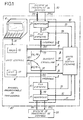
- the system S1 transmits incoming messages ME to the programmable transcoding device AT via a unidirectional data transmission link 111.
- An incoming message consists of a single incoming word (CE) or of a sequence of N incoming binary words [(CE1), (CE2), ... (CE n ), ... (CE N )], N being a variable integer which can vary from 1 to a predetermined maximum integer Nmax and representing the length of the incoming message.
- Each of the incoming words of a series of words corresponds to a rank n, n being an integer between 1 and N, representative of its chronological order of arrival in the transcoding apparatus AT with respect to the first recognized word (CE1) of the incoming suite.
- the incoming words (CE) and (CE1), (CE2), ... (CE n ), ... (CE N ) correspond in the system alphabet S1 of the characters CE and CE1, CE2, ... CE n , ... CE N respectively.
- Each incoming word is received in the transcoding device AT by an input interface 1 via the transmission link 111.
- a dialogue link 111a is provided between the system S1 and the interface 1 so that the latter can invite the S1 system, if necessary, to suspend the transmission.
- This dialogue link 111a can be suppressed by the use of control characters, which can be characters, "XON” and "XOFF", to authorize and suspend the transmission respectively.
- the control characters, "XON” and "XOFF” are then transmitted to the system S1 via the transmission link 111, which in this case is bidirectional.
- the interface 1 comprises an input adapter 11 and a queue 12.
- the input adapter 11 serves to adapt the data transmission link 111, which can be of the serial or parallel type, to internal buses of the AT transcoding device.
- the adapter 111 can be a specialized circuit for this type of transmission, such as a UART (Universal Asynchronous Receiver Transmitter), or more simply a serial register.
- UART Universal Asynchronous Receiver Transmitter
- - parallel in the case of a parallel transmission link 111, input buffer memories, called “buffers”, may be suitable.
- the queue 12 receives the incoming words delivered by the adapter 11 in parallel format through a bus 112.
- the queue 12 is a storage register of FIFO (First in, First out) type.
- the adapter 11 For each incoming word (CE) received, the adapter 11 delivers a word detection signal to a unit via a link 32. exchange management 3. The incoming word (CE) is then presented as an output on the bus 112 connected to the entry to the queue 12. The management unit 3 being notified of the arrival of a word through the link 32, a storage control signal is applied to the queue 12, by a link 33, to memorize in the queue 12 the incoming word (CE) present in the bus 112.
- Processing and control means are included in the transcoding apparatus AT in the form of a central unit 4.
- the unit 4 contains a read-only memory 42 of the PROM type containing micro-instructions for executing a transcoding algorithm and to control the exchange management unit 3.
- the central unit 4 delivers control words to the management unit 3 via a control bus 41.
- the central unit 4 is constantly informed of the state of the transcoding device by a status word delivered by the exchange management unit 3 in a status bus 36.
- the central unit 4 is ready to read an incoming word (CE) stored in the queue wait 12, in order to carry out transcoding processing, it transmits to the exchange management unit 3 a control word by the control bus 41.
- CE incoming word
- the management unit 3 decodes this control word, generates a signal via link 33 to signify queue 12 to present on a bus output 122 connected to an input 51 of a switching device 5, the first incoming word (CE) in chronological order of arrival.
- the word (CE) being present on the bus 122, the management unit then supplies the signaling device 5 with a signal via a link 35, to control the connection of the input 51 to an input / output 52 of the switching device 5.
- the input / output 52 is connected to the central unit 4 by a data bus 521.
- the central unit 4 reads the incoming word (CE) presented on the bus 521.
- the incoming word (CE) is identified in the central unit 4 using transcoding tables contained in a random access memory 43 of the RAM type.
- the incoming word (CE) can be identified as having no corresponding transcoded outgoing message, in which case it is not taken into account.
- the central unit 4 then controls the reading of the next incoming word in the queue 12 in the manner which comes to be described, by transmitting a command word to the exchange management unit 3 via the bus 41.
- the incoming word (CE) can be identified as the first word (CE1) of a series of N incoming words known by the central unit 4.
- the central unit 4 then reads and identifies the following words of the incoming sequence.
- the incoming word (CE) or following N incoming words [(CE1), (CE2), ... (CE n ), ... (CE N )] constituting an incoming message ME can correspond to an outgoing transcoded message MS composed of an outgoing word (CS) or of a sequence of M outgoing transcoded words [(CS1), (CS2), ... (CS m ), ... (CS M )] where m is an integer understood between 1 and M, and M is a variable integer, generally different from the integer N, which can vary from 0 to a predetermined maximum number Mmax and representing the length of the outgoing message MS.
- the central unit 4 supplies the exchange management unit 3 with another word control by the bus 41 in order to control the routing of each of the outgoing words of the message MS to an output interface 2 transmitting transcoded outgoing words (CS), via a transmission link 211, to the second system S2.
- the management unit 3 On receipt of the command word, the management unit 3 causes the input / output 52 of the switching device 5 to be connected with an output 53 of the same device 5, by activating the control link 35.
- the output 53 is connected by a bus 222 to the input of a queue 22, similar to the queue 12, included in the output interface 2.
- Each of the transferred outgoing words is stored, in response to a control signal delivered by the management unit 3 via a control link 38, in the queue 22, with transcoded outgoing words to be transmitted to the system S2.
- the output interface 2 comprises, in addition to the queue 22, an output adapter 21 connected as an output to the second system S2 by the transmission link 211 and a dialog link 211a.
- the link 211a can, similarly, as the dialogue link 111a, be suppressed by the use of the already mentioned command characters "XON" and "XOFF".
- the function of adapter 21 is, as is the input adapter 11, to adapt the internal buses of the transcoding device to the unidirectional transmission link 211, which can be, like the link 111, of the serial or parallel type.
- a link bus 221 provides transcoded outgoing words from the queue 22 at the input of the adapter 21.
- the adapter 21 When the adapter 21 is ready to transmit an outgoing word (CS) stored in the queue 22, it signals this to the exchange management unit 3 via a link 39.
- the management unit 3 then orders, via the link 38, the queue 22 to present an outgoing word as an output on the bus 221 (CS).
- the outgoing word (CS) is read by the adapter 21 which transmits it via the link 211 to the system S2.
- the exchange management unit 3 performs the management and control of the signals exchanged between the different circuits of the transcoding apparatus as well as between the transcoding apparatus and the systems S1 and S2.
- the management unit 3 receives from the central unit 4 a control word relating to the exchanges of data inside the transcoding apparatus from which various control signals are sent sent to the interfaces 1 and 2 by the links. 31, 33, 38, and 40, as well as to the switching device 5 by the link 35.
- a status word is provided by the exchange management unit 3 to the central unit 4, through the bus 36 to inform it of any change in communication with the S1 or S2 system.
- the exchange management unit 3 are provided in a known manner, two write and read counters and a comparator associated with each of the two queues in order to determine the respective filling level of each of the queues. and to compare said levels with high and low filling thresholds defined so as to regulate the bit rates, on the one hand between the system S1 and the transcoding device AT and on the other hand between the transcoding device AT and the S2 system, which in general are different.
- the high and low thresholds make it possible, for each queue, to manage a flow control according to a hysteresis cycle intended to avoid a deterioration of the performance of the device during oscillation around a threshold single filling. So when a queue, 12 or 22, reaches a filling level at least equal to the high threshold, a detection is made by the associated comparator and the exchange management unit 3 suspends the filling of the queue concerned by stopping the transmission and the writing of words in the file. The exchange management unit 3 again authorizes the writing of words in the queue, when the filling level of the queue becomes less than or equal to the low threshold.
- a filling indicator for a queue can take two states, a "filling suspension” state and a "normal operation” state. An indicator comes to the "filling suspension” state when the exchange management unit 3 detects a filling level equal to or greater than the high threshold for the corresponding queue. An indicator comes to the "normal operation” state when the exchange management unit 3 detects a filling level equal to or less than the low threshold of the corresponding queue.
- Exceeding the high threshold in the queue 22 causes the transmission of a status word intended for the central unit 4, via the status bus 36.
- the unit 4 then suspends writing of outgoing words in the queue 22 and any request to read, via the bus 41, the word contained in the queue 12.
- a high threshold exceeded in the queue 12 results in activation of the link 111a to the S1 system so as to stop the transmission of incoming words.
- the exchange management unit 3 is connected to the adapter 11, by the control link 31.
- a filling level of the queue 22 less than or equal to the low threshold causes, if the filling indicator associated with the queue 22 was set to the "filling suspension" state, the transmission of a status word intended for the central unit 4, via the status bus 36. The unit 4 then resumes the writing of outgoing words in the queue 22 and the requests to read the queue waiting 12.
- a filling level of the queue 12 lower than or equal to the low threshold causes, if the filling indicator associated with the queue 12 was set to the state "suspension of filling", the transmission of a command on the link 31 intended to deactivate the link 111a.
- the link 211a between the system S2 and the adapter 21 is provided so that the system S2 requests to suspend, that is to say to stop or delay, a transmission of outgoing words, for example, following d 'a failure or a filling of buffers in the S2 system.
- the request for suspension is transmitted by the adapter 21 to the exchange management unit 3, which validates it by delivering to the adapter 21, via the link 40, a command to stop transmission to the system S2.
- the transcoding device continues to operate with the system S1 until a possible stop caused by an overshoot of the high threshold in the queue 12.
- the adapter 21 informs the unit 3, which takes this new state into account and delivers to the adapter 21, via the link 40, an authorization to transmit to the system S2 .
- the transcoding tables are downloaded into random access memory 43 in the central unit 4 during a preliminary initialization phase, prior to the putting into operation of the transcoding device.
- a connection 61 is provided between the central unit 4 and a microcomputer 6 having served for the preparation of the tables from an analysis of the character alphabets of the systems S1 and S2, of the different communication possibilities between system S1 and system S2, as well as possible conflicts that may arise between the two systems.
- the microcomputer can also be used for viewing data transmitted by the central unit 4 during the transcoding operations, likely to interest an operator.
- the central unit 4 proceeds to address the different transcoding tables, according to addressing modes known as relative addressing mode and indexed addressing mode.
- the relative addressing mode consists in supplying to a processor, an address word representing an offset to be generally carried out with respect to the value of a program counter in order to obtain an effective address in a memory area.
- the address word is supplied to the processor with the address of a so-called index register containing a value to be added to the address word to obtain an effective address.
- the index is located in RAM and can be modified during the program, which allows great flexibility of addressing.
- Relative and indexed addressing modes are in frequent use for addressing tables, because they simply make it possible to convert data into an address in a table that can be set up indifferently in a memory area.
- the transcoding tables include input tables TE1 to TE Nmax , a message table TM, an ITE index table for addressing the input tables, and an ITM index table for addressing the message table.
- the TE1 to TE Nmax input tables support a logical tree structure for identifying incoming messages. This tree structure includes different tracking possibilities leading to the identification of isolated incoming words or a series of incoming words known by the transcoding device.
- Each of the input tables TE1, TE2, ... TE n , ... TE N , ... TE Nmax is located in random access memory by a table start address (TE1), (TE2), ... (TE n ), ... (TE N ), ... (TE Nmax ) respectively.
- the transcoding in succession of N incoming words uses the input tables TE1 to TE N.
- the incoming words (CE1), (CE2), ... (CE n ), ... (CE N ) address in the TE1 input tables, TE2, ... TE n , ... TE N , with respect to the start addresses (TE1), (TE2), ... (TE n ), ... (TE N ), transcoding words Mt1, Mt2, ... Mt n , ... Mt N respectively.
- the input tables TE2 to TE Nmax are only used for transcoding incoming messages to which more than one outgoing word can correspond, their function being different from that of the input table TE1 they can also be called "tables of referral ".
- Each of the input tables comprises as many transcoding words as different incoming words that can be delivered by the system S1, that is 2 B-1 transcoding words, assuming that each incoming word comprises B bits, typically 8 bits divided into two half-bytes in hexadecimal digital base.
- An incoming word having the value noted “00 H " in hexadecimal numerical base corresponds to a character, noted "NULL" in most standard alphabets.
- the character NHL although it can be treated like any other character, is used in the input tables, or reference tables, TE2 to TE Nmax to take into account incoming messages of greater length.
- Each of the transcoding words Mt n comprises B + 1 bits and is divided into first and second fields ch1 and ch2.
- the first field ch1 is an identification indicator; it is made up of the most significant bit, known as the most significant bit MSB.
- the second field ch2 is composed of the remaining B bits of the transcoding word Mt n .
- the field ch2 is generally an address used by the central unit to continue the transcoding processing; it can also, in the entry table TE1, be an outgoing transcoded word (CS).
- the message table TM is located in RAM by a table start address (TM). Transcoded outgoing messages made up of outgoing words each having B bits are stored in the table TM. A transcoded outgoing message MS is preceded in the table TM by the number M of outgoing words contained in this message.
- the number M and the outgoing words (CS1), (CS2), ... (CS m ), ... (CS M ) of a message MS are respectively stored at addresses AM and AM + 1, AM + 2 , ... AM + m, ... AM + M relative to the address (TM).
- the ITE index table is an intermediate table used by the central unit to address a transcoding word Mt n in an input table TE n ; it contains the table start addresses (TE1) to (TE Nmax ) of the input tables TE1 to TE Nmax .
- the ITE table is stored in memory at a start address (ITE).
- Each of the table start addresses (TE1) to (TE Nmax ) is located in the ITE index table by an address, A1 to A Nmax respectively.
- the ITM index table is an intermediate table used by the central unit to address outgoing transcoded messages MS 'in the message table (TM) from transcoding words Mt' from the input table TE1.
- the ITM table is located in RAM by the start address (ITM).
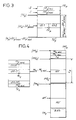
- Fig. 2 shows the use of the transcoding tables by the central unit for three typical cases of transcoding processing.
- an incoming message consisting of a single incoming word (CE) corresponds to a transcoded message composed of a single outgoing transcoded word (CS).
- the incoming word (CE) addresses in the table TE1, with respect to the table start address (TE1), a transcoding word Mt.
- the field ch1 of the word Mt in the binary state "0" indicates to the central unit that the second field ch2 of the word Mt is the outgoing transcoded word (CS).
- an incoming message consisting of a single incoming word (CE ') corresponds to an outgoing transcoded message MS' of length M 'different from 1.
- the fields ch1 and ch2 of a transcoding word Mt' selected by the word (CE ') are then respectively in the binary state "1", unlike the previous case CAS1, and equal to the incoming word (CE').
- the central unit uses the word (CE ') to address an address word AM' in the index table ITM.
- the word AM 'read by the central unit is, in the message table TM, the address of the message MS 'corresponding to the word (CE').
- an incoming message consisting of a series of N incoming words [(CE1), (CE2), ... (CE n ), ... (CE N )] corresponds to an outgoing transcoded message MS comprising a sequence of M outgoing words [(CS1), (CS2), ... (CS m ), ... (CS M )].
- the first incoming word (CE1) selects in the input table TE1 a transcoding word Mt1 having a first field ch1 in the binary state "1".
- the second field ch2 of the word Mt1 is different from the incoming word (CE1), unlike the previous case CAS 2, which allows the central unit to recognize the word (CE1) as being the first word in a known word sequence .
- the field ch2 of the word Mt1 is equal to the address A2 locating the start address (TE2) in the ITE index table.
- a second incoming word (CE2) selects from the table TE2, relative to the start address (TE2) read from the index table ITE, a second transcoding word Mt2 having a first field ch1 in binary state "1 ".
- the field ch1 of the word Mt2 in the binary state "1" confirms the identification path followed and indicates to the central unit that a third incoming word (CE3) is expected.
- the field ch2 of the word Mt2 is the address A3 located in the ITE table, the start address (TE3) of the input table TE3.
- the incoming word (CE3) is used analogously to the word (CE2) to select from the TE3 input table a transcoding word Mt3 whose field ch1 in binary state "1" indicates to the central unit to continue the same process, up to the incoming word (CE N ).
- the incoming word (CE N ) selects in the table TE N a transcoding word Mt N whose field ch1 in binary state "0" allows the central unit to recognize the word (CE N ) as being the last word subsequently known.
- the field ch2 then equal to an address AM of the message table TM is read by the central unit in order to address in the table TM the outgoing transcoded message MS corresponding.
- the number M of words of the message MS stored at the address AM is between 0 and Mmax. For a corresponding MS message, having a single word, the number M is equal to 1.
- a single outgoing word (CS1) is thus read, at the address AM + 1.
- the case CAS3 which has just been described relates to a path in the input tables TE1 to TE Nmax leading directly to the identification of a series of incoming words as being an incoming message to be transcoded known by the central unit.
- an incoming word (CE n ) identified as the n th incoming word of a known sequence of words
- an incoming word (CE n + 1 ) may occur which is not the (n + 1) th expected word from the known sequence of incoming words.
- the incoming word (CE n + 1 ) addresses in the input table TE n + 1 a transcoding word Mt n + 1 having a determined value, for example "00 H ".
- the value "00 H " thus determined is for the central unit a failure code indicating to it, taking into account the last incoming word (CE n + 1 ), either a failure in the transcoding or the existence of a known message longer in length.
- the central unit then initializes the transcoding words Mt1 to Mt n + 1 with new values contained in a table associated with the input tables.
- a new transcoding test is undertaken from the incoming words (CE1) to (CE n + 1 ) previously saved in an incoming word table.
- the table associated with the input tables contains the different possible transcoding words at the same address in an input table; these different words correspond to different possibilities of pathways. Different tracking possibilities can be tried by the central unit before transcoding the words (CE1) to (CE p ), where p is an integer greater than or equal to 1, by one or more transcoded outgoing messages.
- transcoding tables are possible so as to adapt a transcoding to be carried out to addressing possibilities of the central unit necessarily limited and to allow great flexibility in the choice of the values assigned to address words, with respect to the different possible values of the incoming words.
- the size of the input tables TE2 to TE Nmax described above can be significantly reduced by the use of index tables.
- an incoming word (CE p ) addressing an input table TE p where p is an integer between 2 and Nmax, and successfully identified, that is to say identified as being the p th word entering the expected word sequence, is generally between a minimum incoming word (CE p ) minimum and a maximum incoming word (CE p ) maximum leading to success in the identification by the table TE p .
- An ITE p index table associated with the TE p table containing the words (CE p ) mini and (CE p ) max and used for addressing the TE p table makes it possible to limit the size of the input table TE p the number of words between (CE p ) minimum and (CE p ) max .
- the position of the ITE p index table associated with the TE p table is preferably contiguous to the TE p table and precedes the latter in the RAM memory area of the device.
- the words (CE p ) mini and (CE p ) max are thus addressed by making an offset of -2 and -1 respectively with respect to the table start address (TE p ) of the TE p table.
- An incoming word (CE p ) read by the central unit is first compared to the words (CE p ) minimum and (CE p ) maximum . If the incoming word (CE p ) is not included in the range defined by the words (CE p ) minimum and (CE p ) maximum , the central unit directly deduces a failure of the transcoding test in progress.
- the corresponding transcoding word MT p is addressed in the input table TE p from the address of start (TE p ) with the word (CE p ) - (CE p ) mini representing the numerical difference between the words (CE p ) and (CE p ) mini .
- the message table TM can be replaced by Nmax message tables TM1 to TM Nmax respectively associated with the input tables TE1 to TE Nmax .
- an input table TE q where q is an integer between 1 and Nmax, address in the message table TM q associated with it, an outgoing message MS "using respective index tables, IM1 q and IM2 q .
- the IM1 q index table is located by its start address (IM1 q ) and is made up of 3 B-bit words, Mt qmini , Mt qmaxi , and L q .
- the index table IM2 q includes L q words of B bits. Each of the words in the index table IM2 q is an address of an outgoing message in the corresponding message table TM q , relative to a start address (TM q ) of the message table.
- a TM q message table is located by the table start address (TM q ).
- An outgoing message MS "from the message table is addressed in the message table TM q by an address word AM" stored in the index table IM2 q .
- the central unit after checking that the word Mt q is understood between the words Mt qmini and Mt qmaxi , read the address word AM "in the index table IM2 q by addressing it from the start address (IM2 q ) by the numerical difference of the words Mt q and Mt qmini , let Mt q -Mt qmini .
- the tables IM1 q , IM2 q , and TM q are contics in the RAM memory area of the device, as shown in Fig.4.
- the central unit can then deduce the addresses of the start of tables (IM2 q ) and (TM q ) from the address (IM1 q ), from the invariable size of the table IM1 q fixed at 3 words, and of the word L q representing the size of the table IM2 q , and thereby reduces the number of read operations necessary for the addressing of outgoing messages.
- the transcoding device can undergo various modifications to adapt it to different operating modes or to minimize its cost.
- the exchange management unit 3 in the embodiment which has just been described, can be carried out in wired logic using decoders, flip-flops and logic gates, or included in the central unit ensuring exchange management from a firmware contained in read-only memory.
- the exchange management unit in a more sophisticated embodiment, in particular for a bidirectional transcoding apparatus, can be implemented using a microprocessor microcontroller, slave of the central unit and managing communications autonomously.
- the central unit can contain, in read-only memory, software for generating transcoding tables.
- the microcomputer 6 can then be replaced by a simple dialogue terminal, or a hexadecimal keyboard provided with displays, to introduce into the transcoding apparatus various parameters and data to be entered relating to the systems S1 and S2 and to the operating mode. longed for.
- the terminal or the microcomputer 6 may be connected to the transcoding device only during the prior initialization phase, the connection of the terminal to the device which can then be carried out via interface 1 or 2.
Landscapes
- Engineering & Computer Science (AREA)
- Theoretical Computer Science (AREA)
- Communication Control (AREA)
Claims (10)
- Verfahren zur Umcodierung von eingehenden Nachrichten verschiedener Längen in umcodierte ausgehende Nachrichten verschiedener Längen, wobei eine beliebige eingehende Nachricht aus N eingehenden Binärworten besteht, wobei N eine veränderliche ganze Zahl größer oder gleich 1, darstellend die Länge der eingehenden Nachricht ist, und wobei eine umcodierte ausgehende Nachricht aus M ausgehenden Binärworten besteht, wobei M eine veränderliche ganze Zahl größer oder gleich 0 ist, darstellend die Länge der ausgehenden umcodierten Nachricht, dadurch gekennzeichnet, daß jedes eingehende Binärwort einer eingehenden Nachricht verwendet wird, um ein Umcodierungswort in einer entsprechenden Umcodierungstabelle zu adressieren, die einem Rang n des eingehenden Binärwortes in der eingehenden Nachricht zugeordnet ist, wo n eine ganze Zahl ist, enthalten zwischen 1 und N, repräsentativ in ihrer chronologischen Zugangsreihenfolge in bezug auf das erste erkannte Wort der eingehenden Folge, wobei das Umcodierungswort ein erstes Feld und ein zweites Feld aufweist, daß in der dem Rang n gleich 1 zugeordneten Umcodierungstabelle das erste Feld eine Hinweisbezeichnung zur Identifizierung des zweiten Feldes ist, als ob es eine umgeschriebene ausgehende Nachricht mit der Länge M gleich 1 entsprechend einer eingehenden Nachricht mit der Länge N gleich 1 ist oder als ob es eine Adresse in einer Tabelle von umcodierten Nachrichten bezüglich einer umcodierten ausgehenden Nachricht mit der Länge M verschieden von 1 entsprechend einer eingehenden Nachricht mit der Länge N gleich 1 ist oder als ob es eine Adresse der dem Rang n gleich 2 zugeordneten Umcodierungstabelle ist, und daß in den jeweils zugeordneten Umcodierungstabellen mit Rängen n verschieden von 1 das erste Feld eine Hinweisanzeige zur Identifizierung des zweiten Feldes ist, als ob es eine Adresse in der Tabelle von umcodierten Nachrichten, sich beziehend auf eine umcodierte ausgehende Nachricht entsprechend einer eingehenden Nachricht mit der Länge N größer als 1 ist oder als ob es eine Adresse der dem Rang n + 1 zugeordneten Umcodierungstabelle ist oder als ob es ein Abbruchcode ist, wenn die eingehende Nachricht nicht umzucodieren ist.
- Umcodierungsverfahren nach Anspruch 1, dadurch gekennzeichnet, daß die Tabelle von umcodierten Nachrichten in soviele Tabellen von umcodierten Nachrichten wie zugeordnete Umcodierungstabellen unterteilt ist, wobei die Tabellen von umcodierten Nachrichten jeweils den Umcodierungstabellen zugeordnet sind.
- Umcodierungsverfahren nach Anspruch 1 oder 2, für eingehende Binärwörter, aufweisend eine bestimmte ganzzahlige Anzahl von Bits B, dadurch gekennzeichnet, daß die Umcodierungstabellen höchstens 2B-1 binäre Umcodierungswörter umfassen, die jeweils wenigstens B+1 Bits aufweisen.
- Umcodierungsvorrichtung zur Durchführung des Verfahrens nach einem beliebigen der Ansprüche 1 bis 3, dadurch gekennzeichnet, daß sie umfaßt:- erste und zweite Interfacemittel (1, 2) zum Verbinden der Vorrichtung mit ersten und zweiten inkompatiblen numerischen Systemen (S1, S2), die miteinander kommunizieren sollen, über Verbindungen (111, 211), die die eingehenden Nachrichten und die umcodierten ausgehenden Nachrichten durchlaufen,- Verarbeitungsmittel (4), umfassend Umcodierungstabellen (TE, TM, ITE, ITM) und einen programmierten Algorithmus zum Identifizieren der eingehenden Nachrichten und zum aufeinanderfolgenden Ausgeben der entsprechenden umcodierten ausgehenden Nachrichten,- Umschaltmittel (5) zum wechselweisen Verbinden der ersten und zweiten Interfacemittel (1, 2) mit den Verarbeitungsmitteln (4), damit die Verarbeitungsmittel (4) die durch die Interfacemittel (1, 2) ausgegebenen eingehenden Nachrichten aufnehmen und in Reaktion die umcodierten, den Interfacemitteln (1, 2) entsprechenden ausgehenden Nachrichten übertragen, und- Austauschsteuerungsmittel (3) zum Leiten der Interfacemittel (1, 2) und der Umschaltmittel (5), abhängig von einem von den Verarbeitungsmitteln (4) ausgegebenen binären Steuerwort, und zum Regulieren des Durchsatzes der zwischen der Vorrichtung und den Systemen (S1, S2) ausgetauschten Nachrichten, abhängig von durch die Interfacemittel (1, 2) gelieferten Informationen.
- Umcodierungsvorrichtung nach Anspruch 4, dadurch gekennzeichnet, daß die ersten und zweiten Interfacemittel (1, 2) jeweils Mittel (11, 21) zum Anpassen der Vorrichtung an die Verbindungen (111, 211) vom parallelen Typ und/oder vom seriellen Typ, und Mittel (12, 22) zum Speichern der eingehenden Nachrichten und der umcodierten ausgehenden Nachrichten in der Warteschlange umfassen.
- Umcodierungsvorrichtung nach Anspruch 5, dadurch gekennzeichnet, daß die Austauschsteuerungsmittel (3) obere und untere Auffüllschwellen zum Speichern (12, 22) festlegen und das Auffüllen der Mittel zum Speichern (12, 22) abhängig von einem ausgehend von den Schwellwerten definierten Hysteresezyklus leiten.
- Umcodierungsvorrichtung nach einem beliebigen der Ansprüche 4 bis 6, dadurch gekennzeichnet, daß die Verarbeitungsmittel (4) einen schnellen Speicher (43) für Umcodierungstabellen und einen Algorithmus-Festspeicher (42) umfassen.
- Programmierbare Umcodierungsvorrichtung nach Anspruch 7, dadurch gekennzeichnet, daß die Mittel (6) vorgesehen sind, um die Verarbeitungsmittel (4) zur Zeit einer vorläufigen Umcodierungsphase durch das Laden der Umcodierungstabellen (TE) und anderer Tabellen von der oder den Tabellen von umcodierten Nachrichten (TM) in den schnellen Speicher (43) zu initialisieren.
- Programmierbare Umcodierungsvorrichtung nach Anspruch 8, dadurch gekennzeichnet, daß die Mittel zum Initialisieren (6) Daten im Verlauf der Umcodierung sichtbar machen.
- Programmierbare Umcodierungsvorrichtung nach einem beliebigen der Ansprüche 8 bis 9, dadurch gekennzeichnet, daß die Mittel zum Initialisieren (6) ein Mikrorechner, ein Terminal oder eine hexadezimale Tastatur, umfassend Anzeigeeinrichtungen sind.
Applications Claiming Priority (2)
| Application Number | Priority Date | Filing Date | Title |
|---|---|---|---|
| FR8618099A FR2608806B1 (fr) | 1986-12-23 | 1986-12-23 | Procede et appareil programmable pour le transcodage de chaines de caracteres |
| FR8618099 | 1986-12-23 |
Publications (2)
| Publication Number | Publication Date |
|---|---|
| EP0272969A1 EP0272969A1 (de) | 1988-06-29 |
| EP0272969B1 true EP0272969B1 (de) | 1992-05-20 |
Family
ID=9342251
Family Applications (1)
| Application Number | Title | Priority Date | Filing Date |
|---|---|---|---|
| EP87402737A Expired - Lifetime EP0272969B1 (de) | 1986-12-23 | 1987-12-02 | Verfahren und programmierbare Vorrichtung zur Umkodierung von Zeichenketten |
Country Status (4)
| Country | Link |
|---|---|
| US (1) | US4866445A (de) |
| EP (1) | EP0272969B1 (de) |
| DE (1) | DE3779278D1 (de) |
| FR (1) | FR2608806B1 (de) |
Families Citing this family (26)
| Publication number | Priority date | Publication date | Assignee | Title |
|---|---|---|---|---|
| US5231599A (en) * | 1988-12-01 | 1993-07-27 | Bull Hn Information Systems Inc. | Semantic interpreter for an incoming data stream |
| US5006849A (en) * | 1989-07-26 | 1991-04-09 | Astro, Inc. | Apparatus and method for effecting data compression |
| US5050121A (en) * | 1990-01-22 | 1991-09-17 | Vaughan H W | Communication system which uses characters that represent binary-coded decimal numbers |
| JP2639169B2 (ja) * | 1990-04-09 | 1997-08-06 | 三菱電機株式会社 | 数値制御装置 |
| EP0688104A2 (de) * | 1990-08-13 | 1995-12-20 | Fujitsu Limited | Verfahren und Vorrichtung zur Datenkomprimierung |
| US5794144A (en) * | 1994-03-11 | 1998-08-11 | Bellsouth Corporation | Methods and apparatus for communicating data via a cellular mobile radiotelephone system |
| JP3025827B2 (ja) * | 1993-09-14 | 2000-03-27 | 松下電器産業株式会社 | 可変長コード化装置 |
| US5572207A (en) * | 1994-09-23 | 1996-11-05 | International Business Machines Corporation | Method and apparatus for numeric-to-string conversion |
| JP3495122B2 (ja) * | 1995-01-11 | 2004-02-09 | 富士通株式会社 | 携帯型端末装置 |
| US5793869A (en) * | 1996-10-11 | 1998-08-11 | Claflin, Jr.; Raymond E. | Method and apparatus for encoding and data compressing text information |
| US6311056B1 (en) * | 1998-05-21 | 2001-10-30 | Cellemetry Llc | Method and system for expanding the data capacity of a cellular network control channel |
| US6311060B1 (en) | 1998-05-21 | 2001-10-30 | Cellemetry Llc | Method and system for registering the location of a mobile cellular communications device |
| US6738647B1 (en) | 1999-04-23 | 2004-05-18 | Numerex Corporation | Method and system for expanding the data payload of data messages transported via a cellular network control channel |
| US6401132B1 (en) | 1999-08-03 | 2002-06-04 | International Business Machines Corporation | Subchaining transcoders in a transcoding framework |
| US7783508B2 (en) | 1999-09-20 | 2010-08-24 | Numerex Corp. | Method and system for refining vending operations based on wireless data |
| US6718177B1 (en) | 1999-09-20 | 2004-04-06 | Cellemetry, Llc | System for communicating messages via a forward overhead control channel for a programmable logic control device |
| US6856808B1 (en) | 1999-10-29 | 2005-02-15 | Cellmetry, Llc | Interconnect system and method for multiple protocol short message services |
| US6313768B1 (en) * | 2000-03-31 | 2001-11-06 | Siemens Information And And Communications Networks, Inc. | System and method for trace diagnostics of telecommunications systems |
| US6388589B1 (en) * | 2000-07-17 | 2002-05-14 | Trw Inc. | Programmable video interface |
| US7245928B2 (en) | 2000-10-27 | 2007-07-17 | Cellemetry, Llc | Method and system for improved short message services |
| US6718237B1 (en) | 2002-03-28 | 2004-04-06 | Numerex Investment Corp. | Method for reducing capacity demands for conveying geographic location information over capacity constrained wireless systems |
| US7323970B1 (en) | 2004-01-21 | 2008-01-29 | Numerex Corporation | Method and system for remote interaction with a vehicle via wireless communication |
| WO2007136723A2 (en) | 2006-05-17 | 2007-11-29 | Numerex Corp. | System and method for prolonging wireless data product's life |
| US20100268589A1 (en) | 2007-02-06 | 2010-10-21 | Philip Wesby | System and Method for Data Acquisition and Processing |
| US8583626B2 (en) | 2012-03-08 | 2013-11-12 | International Business Machines Corporation | Method to detect reference data tables in ETL processes |
| US8954376B2 (en) * | 2012-03-08 | 2015-02-10 | International Business Machines Corporation | Detecting transcoding tables in extract-transform-load processes |
Family Cites Families (6)
| Publication number | Priority date | Publication date | Assignee | Title |
|---|---|---|---|---|
| IT593435A (de) * | 1957-08-08 | 1900-01-01 | ||
| US3701111A (en) * | 1971-02-08 | 1972-10-24 | Ibm | Method of and apparatus for decoding variable-length codes having length-indicating prefixes |
| US3925780A (en) * | 1973-12-26 | 1975-12-09 | Ibm | Apparatus for data compression encoding and decoding |
| US4425626A (en) * | 1979-11-29 | 1984-01-10 | Honeywell Information Systems Inc. | Apparatus for translation of character codes for application to a data processing system |
| US4644545A (en) * | 1983-05-16 | 1987-02-17 | Data General Corporation | Digital encoding and decoding apparatus |
| JPS61214685A (ja) * | 1985-03-20 | 1986-09-24 | Sony Corp | デ−タ変換装置 |
-
1986
- 1986-12-23 FR FR8618099A patent/FR2608806B1/fr not_active Expired
-
1987
- 1987-12-02 DE DE8787402737T patent/DE3779278D1/de not_active Expired - Lifetime
- 1987-12-02 EP EP87402737A patent/EP0272969B1/de not_active Expired - Lifetime
- 1987-12-23 US US07/137,141 patent/US4866445A/en not_active Expired - Fee Related
Also Published As
| Publication number | Publication date |
|---|---|
| FR2608806B1 (fr) | 1989-03-17 |
| US4866445A (en) | 1989-09-12 |
| EP0272969A1 (de) | 1988-06-29 |
| FR2608806A1 (fr) | 1988-06-24 |
| DE3779278D1 (de) | 1992-06-25 |
Similar Documents
| Publication | Publication Date | Title |
|---|---|---|
| EP0272969B1 (de) | Verfahren und programmierbare Vorrichtung zur Umkodierung von Zeichenketten | |
| FR2773935A1 (fr) | Procedes de communication entre systemes informatiques et dispositifs les mettant en oeuvre | |
| FR2728364A1 (fr) | Interface d'entree-sortie connectee a une memoire d'ordinateur et capable de controler les vitesses d'entree-sortie de donnee | |
| FR2508200A1 (fr) | Circuit d'interface de canal | |
| FR2480460A1 (fr) | Dispositif pour transferer des informations entre des unites principales d'un systeme de traitement de donnees et un sous-systeme central | |
| FR2737029A1 (fr) | Dispositif d'interface entre un calculateur a architecture redondante et un moyen de communication | |
| EP0005722A1 (de) | Auswahlsystem für Vorrangsschnittstellen | |
| EP0889429B1 (de) | Chipkartenleser unter Verwendung eines schnellen Übertragungsprotokolls | |
| EP0089440B1 (de) | Verfahren und Einrichtung zum Informationsaustausch zwischen Terminals und einer zentralen Steuereinheit | |
| US11354094B2 (en) | Hierarchical sort/merge structure using a request pipe | |
| US10936283B2 (en) | Buffer size optimization in a hierarchical structure | |
| EP1205849A1 (de) | Programierbare Adaptervorrichtung für Komunikationsprotokolle | |
| FR2536882A1 (fr) | Interface de gestion d'echanges d'informations sur un bus de communication entre au moins une unite de controle et des unites peripheriques ou entre ces unites peripheriques | |
| US11048475B2 (en) | Multi-cycle key compares for keys and records of variable length | |
| US10896022B2 (en) | Sorting using pipelined compare units | |
| FR2744539A1 (fr) | Systeme et procede de traitement par augmentation du nombre d'entrees de donnees | |
| EP2497235B1 (de) | Diagnoseinstrument für breitbandnetze | |
| FR2520956A1 (fr) | Systeme de transmission asynchrone, notamment pour systeme de videotex interactif | |
| EP1557765A1 (de) | Hierarchisches Arbitrierungsverfahren | |
| EP0974902B1 (de) | Verfahren um Fehler auf einer seriellen Verbindung einer integrierten Schaltung zu erkennen und Vorrichtung zur Durchführung des Verfahrens | |
| EP0191999B1 (de) | Verfahren zur Adressierung in einem Nachrichtennetzwerk zwischen einer Nachrichten aussendenden Station und mindestens einer Empfangsstation und Vorrichtung zur Durchführung des Verfahrens | |
| EP0100712B1 (de) | System zur Erkennung programmierbaren Stopkodes in einer Datenübertragung zwischen einem lokalen Mikroprozessorspeicher und einer peripheren Einheit, in einer Rechenanlage mit Verwendung einer direkter Zugriffschaltung zu einem lokalen Speicher | |
| JPH02277156A (ja) | 16ビットデータバス上でバイト幅uart転送を実行する技術 | |
| EP0481896B1 (de) | Übertragungssteuerung zwischen einem Rechner und einer Mehrzahl von Datenendgeräten in einem Netzwerk vom CSMA/CD-Typ | |
| EP0507685A1 (de) | Ringkopplungsverfahren für Informationsverarbeitungseinrichtung |
Legal Events
| Date | Code | Title | Description |
|---|---|---|---|
| PUAI | Public reference made under article 153(3) epc to a published international application that has entered the european phase |
Free format text: ORIGINAL CODE: 0009012 |
|
| AK | Designated contracting states |
Kind code of ref document: A1 Designated state(s): DE GB |
|
| 17P | Request for examination filed |
Effective date: 19881213 |
|
| 17Q | First examination report despatched |
Effective date: 19910709 |
|
| GRAA | (expected) grant |
Free format text: ORIGINAL CODE: 0009210 |
|
| AK | Designated contracting states |
Kind code of ref document: B1 Designated state(s): DE GB |
|
| PG25 | Lapsed in a contracting state [announced via postgrant information from national office to epo] |
Ref country code: GB Effective date: 19920520 |
|
| REF | Corresponds to: |
Ref document number: 3779278 Country of ref document: DE Date of ref document: 19920625 |
|
| GBV | Gb: ep patent (uk) treated as always having been void in accordance with gb section 77(7)/1977 [no translation filed] | ||
| PLBE | No opposition filed within time limit |
Free format text: ORIGINAL CODE: 0009261 |
|
| STAA | Information on the status of an ep patent application or granted ep patent |
Free format text: STATUS: NO OPPOSITION FILED WITHIN TIME LIMIT |
|
| 26N | No opposition filed | ||
| PG25 | Lapsed in a contracting state [announced via postgrant information from national office to epo] |
Ref country code: DE Effective date: 19931001 |