EP0273213A1 - Structure de caillebottis pour transporteur à chaînes à barreaux - Google Patents
Structure de caillebottis pour transporteur à chaînes à barreaux Download PDFInfo
- Publication number
- EP0273213A1 EP0273213A1 EP87117674A EP87117674A EP0273213A1 EP 0273213 A1 EP0273213 A1 EP 0273213A1 EP 87117674 A EP87117674 A EP 87117674A EP 87117674 A EP87117674 A EP 87117674A EP 0273213 A1 EP0273213 A1 EP 0273213A1
- Authority
- EP
- European Patent Office
- Prior art keywords
- grill
- conveyor
- cross bars
- fact
- wave
- Prior art date
- Legal status (The legal status is an assumption and is not a legal conclusion. Google has not performed a legal analysis and makes no representation as to the accuracy of the status listed.)
- Withdrawn
Links
- 239000002184 metal Substances 0.000 claims abstract 3
- 238000005452 bending Methods 0.000 claims description 7
- 230000000149 penetrating effect Effects 0.000 claims 1
- 230000000063 preceeding effect Effects 0.000 claims 1
- 235000013601 eggs Nutrition 0.000 description 2
- 239000000975 dye Substances 0.000 description 1
- 238000012423 maintenance Methods 0.000 description 1
- 230000000284 resting effect Effects 0.000 description 1
Images

Classifications
-
- B—PERFORMING OPERATIONS; TRANSPORTING
- B65—CONVEYING; PACKING; STORING; HANDLING THIN OR FILAMENTARY MATERIAL
- B65G—TRANSPORT OR STORAGE DEVICES, e.g. CONVEYORS FOR LOADING OR TIPPING, SHOP CONVEYOR SYSTEMS OR PNEUMATIC TUBE CONVEYORS
- B65G17/00—Conveyors having an endless traction element, e.g. a chain, transmitting movement to a continuous or substantially-continuous load-carrying surface or to a series of individual load-carriers; Endless-chain conveyors in which the chains form the load-carrying surface
- B65G17/06—Conveyors having an endless traction element, e.g. a chain, transmitting movement to a continuous or substantially-continuous load-carrying surface or to a series of individual load-carriers; Endless-chain conveyors in which the chains form the load-carrying surface having a load-carrying surface formed by a series of interconnected, e.g. longitudinal, links, plates, or platforms
- B65G17/063—Conveyors having an endless traction element, e.g. a chain, transmitting movement to a continuous or substantially-continuous load-carrying surface or to a series of individual load-carriers; Endless-chain conveyors in which the chains form the load-carrying surface having a load-carrying surface formed by a series of interconnected, e.g. longitudinal, links, plates, or platforms the load carrying surface being formed by profiles, rods, bars, rollers or the like attached to more than one traction element
- B65G17/064—Conveyors having an endless traction element, e.g. a chain, transmitting movement to a continuous or substantially-continuous load-carrying surface or to a series of individual load-carriers; Endless-chain conveyors in which the chains form the load-carrying surface having a load-carrying surface formed by a series of interconnected, e.g. longitudinal, links, plates, or platforms the load carrying surface being formed by profiles, rods, bars, rollers or the like attached to more than one traction element the profiles, rods, bars, rollers or the like being interconnected by a mesh or grid-like structure
-
- B—PERFORMING OPERATIONS; TRANSPORTING
- B65—CONVEYING; PACKING; STORING; HANDLING THIN OR FILAMENTARY MATERIAL
- B65G—TRANSPORT OR STORAGE DEVICES, e.g. CONVEYORS FOR LOADING OR TIPPING, SHOP CONVEYOR SYSTEMS OR PNEUMATIC TUBE CONVEYORS
- B65G2201/00—Indexing codes relating to handling devices, e.g. conveyors, characterised by the type of product or load being conveyed or handled
- B65G2201/02—Articles
Definitions
- This invention refers to a grill structure for an endless conveyor, and specifically to a bar-chain conveyor provided with a grill structure which forms a conveying surface which can shift slightly relative to the conveyor bars allowing the conveyor to curve freely in any direction in space, without impeding its sliding motion.
- This invention also refers to a particular embodiment of the grill structure as well as to endless conveyors that employ the abovementioned belt and grill structure.
- Patents FR-A-2.162.150 and US-A-4.244.464 describe metallic conveyor belts, specifically meant for the conveyance of eggs or the like.
- Said belts consist of two lateral chains of the round-link type where each link in one chain is connected to a link in the opposite chain by a cross bar.
- the cross bars are spaced out at a constant pitch, along the length of the belt, which reflects the distance between the links on the chain.
- Belts of the type mentioned are paticularly suitable to transport eggs, or rather to transport articles the size of which will prevent them from falling through the gaps between the cross bars. Such belts are therefore unsuitable for conveying of small articles that require a wide and stable resting surface. Increasing the thickness or width of the cross bars or positioning the bars closer together by using chains with smaller links isn't always possible or advisable since these measures entail enormously heavy conveyor belt structures which may have to be dragged over considerable distances. This solution is also impractical due to the high cost of such a belt. It would be, instead, desirable to have belt structures of the type mentioned above that, in addition to providing a wide and stable surface and being suitable for the conveyance of small articles, would also be inexpensive and light in weight, so as to allow transport speeds suitable for operational requirements.
- the object of this invention is to provide a grill structure for conveyor belts in general or for conveyor belts of the type described above, that is to say with cross bars fastened to lateral driving chains, which can be used and marketed as is for several applications and which, when necessary, can be combined by the manufacturer or user with a grill structure suitable for providing a wide and stable transport surface to support articles to be conveyed.
- a further object of this invention is to provide a grill structure for a conveyor belt of the type mentioned above which is extremely simple, easy to assemble and requires a minimal amount of maintenance and in which the grill that forms the conveying surface of the belt can be easily mounted or removed without having to disassemble the belt or the whole conveyor.
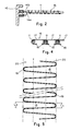
- Figures 1 through 4 show part of a conveyor belt 10 of the type comprising cross bars 11, in which each bar 11 is fastened or welded to the links 14a, 14b of two driving chains 12 which, in the example, are round-link chains, with rings 14a and 14b laid out alternatively at 90 angles to each other and in which the chain links run along guide rails 15 in a previously known manner. It is important to note, however, that for the purposes of this invention, the way in which the lateral chains of the conveyor belt are made and the way in which the cross bars 11 are interconnected, which depends on the application for which the conveyor belt is designed, are not relevant.
- the conveyor belt 11, shown in figure 1 and 2 also comprises a grill structure 16 which hooks onto and overlap the bars 11 forming the entire conveying surface of the belt.
- the structure of the grill 16 is shown in greater detail in the enlarged views of figures 3 and 4 and consists of separate flat grill members 17 each member 17 being hooked onto two contiguous bars 11 of the belt.
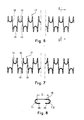
- the grill members 17 are shown in detail in figures 6, 7 and 8 and are made out of a wave bent or shaped wire cut to the required size and bent on the sides starting from continuous wave or zigzag-shaped wire shown in figure 5.
- the grill members 17 are made from a flat zigzag-shaped wire which is made by alternatively bending wire using appropriate dyes in order to make a sequence of bends or waves each of which has two sides or linear arms 18 which diverge from each other towards the side opposite to the bend or bottom loop portion 19 of each wave.
- the arms of the waves must be angled, in the example shown, so that the width L1 measured from the outside at one side of each grill member 17 is equal to, or slightly less than the width L2 measured from the inside at the opposite side, said width L1 and L2 depending not only on the angle of the straight sides or arms 18 but also on their length and the thickness of the wire being used.
- the wave-shaped wire 17 in figure 5 is thus cut to a pre-set size that corresponds to the width of the grill 16 of the belt to be constructed, after which the loops 19 along the two side hands 20 of the wave-shaped wire 17 are bent on one side to form hooking means, that is downward and inward, thus taking on a C-shape shown in figures 6, 7 and 8.
- the loop portions it is necessary to insure that the bending radius of the tool around which said loop portions are laterally bent is slightly larger than that of the cross bars 11 of the belt, thus resulting in a loose fit which allows relative shifting and sliding movement that is necessary amongst the cross bars 11 and the grill 16 when the conveyor belt goes around a curve in its path.
- the assembling of the grill members described above is carried out as follows: after having prepared the grill members 17 necessary to form the grill surface for the whole belt to be completed, given a bar-chain belt of the specified size, of the type shown in figure 1 for instance, start from one end of the belt by hooking up the C-shaped loops 19 on one side of a grill member 17 to a first cross bar 11 on the belt; the next cross bar 11 is then pulled next to the first one thanks to the sliding movement between the lateral chain links until it is hooked by the C-shaped loop portions 19 on the opposite side of the same grill member.
- Another grill member is then attached by hooking the C-shaped loops on one side of the waves onto a second cross bar, laying said C-shaped loops of the second grill member between the wider ends of the waves of the first grill member, and so on, fastening one grill member after the other until the grill surface for the whole conveyor belt is completed.
- the extreme operational versatility of the grill structure described in this invention is shown by the preceding remarks.
- the bar-chain conveyor belt can, in fact, be marketed in its traditional form, that is without the metallic grill 16, and, if needed, the grill can be provided by hooking up the grill members 17 in the manner described above, either on a fully assembled conveyor belt or on one that is yet to be installed, on certain portions of the belt or on the whole conveyor. Furthermore, if part of the grill wears out, the single worn grill members can easily be substituted with new ones, while the other grill links remain hooked to the belt's bars.
- Both the bar-chain conveyor belt and single grill members while respecting the principles embodied in this invention, can be built in a different manner from the described one, while maintaining the advantages and characteristics mentioned above; specifically that the cross bar belt 10, instead of being of the round-link chain type, could be of another type with the cross bars connected to articulated connection flat links or the bars themselves could be shaped to be interconnected among themselves. Additionally, the single grill members 17 and the same loop portions 19 can be shaped differently, without departing from the invention as claimed.
Landscapes
- Engineering & Computer Science (AREA)
- Mechanical Engineering (AREA)
- Chain Conveyers (AREA)
- Belt Conveyors (AREA)
Applications Claiming Priority (2)
| Application Number | Priority Date | Filing Date | Title |
|---|---|---|---|
| IT2257486 | 1986-12-04 | ||
| IT22574/86A IT1199700B (it) | 1986-12-04 | 1986-12-04 | Struttura di griglia per nastri trasportatore a barre |
Publications (1)
| Publication Number | Publication Date |
|---|---|
| EP0273213A1 true EP0273213A1 (fr) | 1988-07-06 |
Family
ID=11197994
Family Applications (1)
| Application Number | Title | Priority Date | Filing Date |
|---|---|---|---|
| EP87117674A Withdrawn EP0273213A1 (fr) | 1986-12-04 | 1987-11-30 | Structure de caillebottis pour transporteur à chaînes à barreaux |
Country Status (2)
| Country | Link |
|---|---|
| EP (1) | EP0273213A1 (fr) |
| IT (1) | IT1199700B (fr) |
Cited By (3)
| Publication number | Priority date | Publication date | Assignee | Title |
|---|---|---|---|---|
| EP1616817A1 (fr) * | 2004-07-13 | 2006-01-18 | Alit S.r.l. | Revêtement modulaire remplaçable par encliquetage pour transporteurs à bande à renvoi-courbe du type à tiges et maillons |
| WO2019055797A1 (fr) * | 2017-09-15 | 2019-03-21 | Ashworth Bros., Inc. | Recouvrement en spirale de courroie transporteuse ayant des boucles intermédiaires |
| US10507978B2 (en) | 2017-10-28 | 2019-12-17 | Rabbit Designs LLC | Radius and variable width conveyor belt |
Citations (6)
| Publication number | Priority date | Publication date | Assignee | Title |
|---|---|---|---|---|
| DE259622C (fr) * | ||||
| DE419892C (de) * | 1925-01-08 | 1925-10-13 | Georg Tieke | Gliederfoerderband mit Drahthakengliedern |
| US3368662A (en) * | 1965-11-04 | 1968-02-13 | Poerink Jannes Jonge | Transport device with conveyor belt guided rectilinear and curvilinear |
| DE7231050U (de) * | 1972-08-22 | 1972-11-23 | Hein Lehmann Ag | Bauelement eines gliederfoerderbandes aus endlos geschlungenem draht |
| US4244464A (en) * | 1979-12-05 | 1981-01-13 | Gebr. Van Capelleveen B.V. | Conveyor, in particular for eggs |
| EP0038461A2 (fr) * | 1980-04-21 | 1981-10-28 | Draadindustrie Jonge Poerink B.V. | Couroie de transport en treillis de fil métallique et procédé pour la fabrication de cette courroie |
-
1986
- 1986-12-04 IT IT22574/86A patent/IT1199700B/it active
-
1987
- 1987-11-30 EP EP87117674A patent/EP0273213A1/fr not_active Withdrawn
Patent Citations (6)
| Publication number | Priority date | Publication date | Assignee | Title |
|---|---|---|---|---|
| DE259622C (fr) * | ||||
| DE419892C (de) * | 1925-01-08 | 1925-10-13 | Georg Tieke | Gliederfoerderband mit Drahthakengliedern |
| US3368662A (en) * | 1965-11-04 | 1968-02-13 | Poerink Jannes Jonge | Transport device with conveyor belt guided rectilinear and curvilinear |
| DE7231050U (de) * | 1972-08-22 | 1972-11-23 | Hein Lehmann Ag | Bauelement eines gliederfoerderbandes aus endlos geschlungenem draht |
| US4244464A (en) * | 1979-12-05 | 1981-01-13 | Gebr. Van Capelleveen B.V. | Conveyor, in particular for eggs |
| EP0038461A2 (fr) * | 1980-04-21 | 1981-10-28 | Draadindustrie Jonge Poerink B.V. | Couroie de transport en treillis de fil métallique et procédé pour la fabrication de cette courroie |
Cited By (4)
| Publication number | Priority date | Publication date | Assignee | Title |
|---|---|---|---|---|
| EP1616817A1 (fr) * | 2004-07-13 | 2006-01-18 | Alit S.r.l. | Revêtement modulaire remplaçable par encliquetage pour transporteurs à bande à renvoi-courbe du type à tiges et maillons |
| WO2019055797A1 (fr) * | 2017-09-15 | 2019-03-21 | Ashworth Bros., Inc. | Recouvrement en spirale de courroie transporteuse ayant des boucles intermédiaires |
| US10507978B2 (en) | 2017-10-28 | 2019-12-17 | Rabbit Designs LLC | Radius and variable width conveyor belt |
| US10633187B2 (en) | 2017-10-28 | 2020-04-28 | Rabbit Designs LLC | Radius and variable width conveyor belt |
Also Published As
| Publication number | Publication date |
|---|---|
| IT1199700B (it) | 1988-12-30 |
| IT8622574A0 (it) | 1986-12-04 |
Similar Documents
| Publication | Publication Date | Title |
|---|---|---|
| EP2871144B1 (fr) | Courroies de transport à espacement variable avec des extrémités de tige de sertissage | |
| US5004097A (en) | Replaceable snap-on modular overlay for rod and link turn-curve conveyor belts | |
| EP0478833B1 (fr) | Bande transporteuse | |
| EP0521506B1 (fr) | Bande transporteuse modulaire en matière plastique | |
| US5501319A (en) | Conveyor belt with asymmetric edge links | |
| US4645070A (en) | Dual bend conveyor | |
| US4754871A (en) | Wire mesh belt and splicer | |
| KR101804010B1 (ko) | 복합 링크를 갖는 컨베이어 벨트 | |
| EP1009688B1 (fr) | Bande transporteuse presentant un espacement variable et procede de fabrication | |
| US5303817A (en) | Drive system for modular link conveyor belts | |
| US5197591A (en) | Replaceable snap-on modular overlay for rod and link turn-curve conveyor belts | |
| EP1223119A1 (fr) | Convoyeur en fil métallique tissé dont les mailles ont une forme composée | |
| EP0273213A1 (fr) | Structure de caillebottis pour transporteur à chaînes à barreaux | |
| CN101835699B (zh) | 输送器和传动带 | |
| US4410083A (en) | Wire-netting conveyor belt, and method of making such wire-netting conveyor belt | |
| EP0502639A1 (fr) | Revêtement modulaire remplaçable par encliquetage pour transporteurs à bande à renvoi-courbe du type à tiges et maillons | |
| US3329256A (en) | Conveyor belt | |
| JPH01247841A (ja) | 高負荷伝動用ベルト | |
| FI72697B (fi) | Anordning vid transportbanor. | |
| US3262546A (en) | Conveyor chain with oppositely directed pushers | |
| SU806558A1 (ru) | Пластинчатое полотно конвейера | |
| SU623784A1 (ru) | Крутонаклонный ленточный конвейер | |
| SU1585249A2 (ru) | Рабочий орган скребкового трубчатого конвейера | |
| SU1164159A1 (ru) | Полотно пруткового конвейера | |
| GB1200324A (en) | Improvements relating to wire conveyor belts |
Legal Events
| Date | Code | Title | Description |
|---|---|---|---|
| PUAI | Public reference made under article 153(3) epc to a published international application that has entered the european phase |
Free format text: ORIGINAL CODE: 0009012 |
|
| AK | Designated contracting states |
Kind code of ref document: A1 Designated state(s): DE FR GB |
|
| STAA | Information on the status of an ep patent application or granted ep patent |
Free format text: STATUS: THE APPLICATION IS DEEMED TO BE WITHDRAWN |
|
| 18D | Application deemed to be withdrawn |
Effective date: 19890107 |
|
| RIN1 | Information on inventor provided before grant (corrected) |
Inventor name: PESSA, LUCIANO |