EP0273231A2 - Vorrichtung zum Regeln insbesondere eines Ammoniakkonverters - Google Patents
Vorrichtung zum Regeln insbesondere eines Ammoniakkonverters Download PDFInfo
- Publication number
- EP0273231A2 EP0273231A2 EP87117925A EP87117925A EP0273231A2 EP 0273231 A2 EP0273231 A2 EP 0273231A2 EP 87117925 A EP87117925 A EP 87117925A EP 87117925 A EP87117925 A EP 87117925A EP 0273231 A2 EP0273231 A2 EP 0273231A2
- Authority
- EP
- European Patent Office
- Prior art keywords
- heat exchanger
- catalyst bed
- gas
- process gas
- control
- Prior art date
- Legal status (The legal status is an assumption and is not a legal conclusion. Google has not performed a legal analysis and makes no representation as to the accuracy of the status listed.)
- Granted
Links
Images



Classifications
-
- C—CHEMISTRY; METALLURGY
- C01—INORGANIC CHEMISTRY
- C01C—AMMONIA; CYANOGEN; COMPOUNDS THEREOF
- C01C1/00—Ammonia; Compounds thereof
- C01C1/02—Preparation, purification or separation of ammonia
- C01C1/04—Preparation of ammonia by synthesis
- C01C1/0405—Preparation of ammonia by synthesis from N2 and H2 in presence of a catalyst
- C01C1/0417—Preparation of ammonia by synthesis from N2 and H2 in presence of a catalyst characterised by the synthesis reactor, e.g. arrangement of catalyst beds and heat exchangers in the reactor
- C01C1/0423—Cold wall reactors
-
- B—PERFORMING OPERATIONS; TRANSPORTING
- B01—PHYSICAL OR CHEMICAL PROCESSES OR APPARATUS IN GENERAL
- B01J—CHEMICAL OR PHYSICAL PROCESSES, e.g. CATALYSIS OR COLLOID CHEMISTRY; THEIR RELEVANT APPARATUS
- B01J8/00—Chemical or physical processes in general, conducted in the presence of fluids and solid particles; Apparatus for such processes
- B01J8/02—Chemical or physical processes in general, conducted in the presence of fluids and solid particles; Apparatus for such processes with stationary particles, e.g. in fixed beds
- B01J8/04—Chemical or physical processes in general, conducted in the presence of fluids and solid particles; Apparatus for such processes with stationary particles, e.g. in fixed beds the fluid passing successively through two or more beds
- B01J8/0403—Chemical or physical processes in general, conducted in the presence of fluids and solid particles; Apparatus for such processes with stationary particles, e.g. in fixed beds the fluid passing successively through two or more beds the fluid flow within the beds being predominantly horizontal
- B01J8/0407—Chemical or physical processes in general, conducted in the presence of fluids and solid particles; Apparatus for such processes with stationary particles, e.g. in fixed beds the fluid passing successively through two or more beds the fluid flow within the beds being predominantly horizontal through two or more cylindrical annular shaped beds
- B01J8/0415—Chemical or physical processes in general, conducted in the presence of fluids and solid particles; Apparatus for such processes with stationary particles, e.g. in fixed beds the fluid passing successively through two or more beds the fluid flow within the beds being predominantly horizontal through two or more cylindrical annular shaped beds the beds being superimposed one above the other
-
- B—PERFORMING OPERATIONS; TRANSPORTING
- B01—PHYSICAL OR CHEMICAL PROCESSES OR APPARATUS IN GENERAL
- B01J—CHEMICAL OR PHYSICAL PROCESSES, e.g. CATALYSIS OR COLLOID CHEMISTRY; THEIR RELEVANT APPARATUS
- B01J8/00—Chemical or physical processes in general, conducted in the presence of fluids and solid particles; Apparatus for such processes
- B01J8/02—Chemical or physical processes in general, conducted in the presence of fluids and solid particles; Apparatus for such processes with stationary particles, e.g. in fixed beds
- B01J8/04—Chemical or physical processes in general, conducted in the presence of fluids and solid particles; Apparatus for such processes with stationary particles, e.g. in fixed beds the fluid passing successively through two or more beds
- B01J8/0496—Heating or cooling the reactor
-
- Y—GENERAL TAGGING OF NEW TECHNOLOGICAL DEVELOPMENTS; GENERAL TAGGING OF CROSS-SECTIONAL TECHNOLOGIES SPANNING OVER SEVERAL SECTIONS OF THE IPC; TECHNICAL SUBJECTS COVERED BY FORMER USPC CROSS-REFERENCE ART COLLECTIONS [XRACs] AND DIGESTS
- Y02—TECHNOLOGIES OR APPLICATIONS FOR MITIGATION OR ADAPTATION AGAINST CLIMATE CHANGE
- Y02P—CLIMATE CHANGE MITIGATION TECHNOLOGIES IN THE PRODUCTION OR PROCESSING OF GOODS
- Y02P20/00—Technologies relating to chemical industry
- Y02P20/50—Improvements relating to the production of bulk chemicals
- Y02P20/52—Improvements relating to the production of bulk chemicals using catalysts, e.g. selective catalysts
Definitions
- the invention relates to a device for regulating in particular an ammonia converter with a process gas inlet and a process gas outlet, at least one heat exchanger and at least one catalyst bed and a further gas supply and with a central tube and a supply of the process gas to the heat exchanger or catalyst bed, the heat exchanger and around this heat exchanger the first catalyst bed is arranged rotationally symmetrical to the central tube.
- a method is known to assemble the process gas stream altogether from two sub-streams, at least one of the sub-streams in temperature and / or quantity is adjustable so as to achieve the desired process conditions.
- the gas streams are combined before entering the first catalyst bed.
- the object of the invention is to provide a solution with which the feed of control gas, quench gas or a part of the process gas with different temperatures and / or other conditions is possible at any point in a reactor in the respective gas streams, the solution being intended to be so that the admixture or the by-pass line is completely lockable or partially loadable or can be opened completely.
- this object is achieved according to the invention in that the central tube for temperature control as the regulating gas supply tube passes completely through the heat exchanger and at least has controllable outlets at its lower end partial admixing of the control gas into the process gas stream before it flows through the catalyst bed and / or for admixing the control gas stream into the process gas stream after its flow through the catalyst bed and the heat exchanger is provided.
- the central, controllable tube ensures that e.g. the control gas can only be fed into the process gas stream in an extreme position across the heat exchanger when it has already flowed through the first catalyst bed and subsequently through the heat exchanger, i.e. e.g. into the gas stream which is to act on the subsequent catalyst bed.
- the invention provides that the guide tubes for the process gas passing through the heat exchanger surround the central, controllable tube at a distance from it.
- This design has the advantage that the design of both the heat exchanger and the centrally passing by-pass pipe is comparatively simple, as a rule special pipe elbows or the like can then be dispensed with.
- the invention also provides that the distribution openings of the central tube are designed to be synchronously controllable as a function of one another.
- the throughput control prefferably to provide the central tube with openings at the lower end which can be closed by a piston provided with axial perforations, these openings opening into a flow channel for the circulating gas.
- a piston provided with axial perforations can either partially open or close the lateral openings in the lower part of the central tube by thrust, but this can also be done by rotation with a corresponding piston design.
- control element to design part of the control element as a cylinder, it is expedient to design the lower end at the end face to be completely sealable via a sealing element coupled to the cylinder, as is also provided by the invention.
- the invention provides that the central tube and / or the actuation of the controllable outlets push through at least one further heat exchanger.
- the particular advantage of the invention consists in the simple control of control gas flows, the respective situation being controllable very precisely, since control gas flows can always be used where they are needed.
- a control device which admixes at least a portion of the colder jacket gas into the process gas Allows entry into the third catalyst bed.
- the colder jacket gas can not only take the usual heating path through the second and first heat exchangers, it is also possible to use part of it as control gas for the third catalyst bed; conversely, this circuit can of course also be used to switch the quantities of jacket gas that make up the upper one first and second catalyst beds are fed, controlled.
- first centric tube is penetrated by a second centric tube, the second centric tube being guided up to below the following heat exchanger and used to admix control gas into the process gas stream upstream of the third catalyst bed.
- the device is essentially formed by a pressure vessel 2, in which two catalyst beds are arranged concentrically to the central axis 3 in the example shown in FIG. 1 and three catalyst beds in the embodiments shown in FIGS.
- the upper and first catalyst beds are designated by 4, the second by 5 and the lower and last (in the exemplary embodiments according to FIGS. 2 to 4) by 6.
- a first heat exchanger 7 is arranged in the interior of the first catalyst bed 4, a second heat exchanger 8 being arranged in the interior of the second catalyst bed 5 in the exemplary embodiments according to FIGS. 2 to 4, the heat exchangers 7 and 8 being functionally connected in series in the latter case.
- the catalysts, including the heat exchanger, are surrounded by an enveloping wall 9 which is dimensioned such that a continuous annular space 10 is formed between the inner surface of the container wall of the enveloping wall 9.
- a cooling gas flows into the device 1 at the top through a nozzle 11, flows through the annular space 10 and emerges at the bottom together with the recycle gas through a nozzle 12.
- the upper inlet port for the cycle gas is designated 13.
- a pipe 14 is provided concentrically in the interior of the heat exchanger 7 and can be acted upon by gas for control purposes via a feed pipe 15.
- This central tube opens into a distribution chamber 16 for the process gas, which has already flowed through the first catalyst bed 4 both inside and outside the heat exchanger 7 and the guide tubes 30.
- a further distribution chamber 17 is provided in a gastight manner, separately from the distribution chamber 16, into which the process gas passes after flowing through guide tubes 30 of the heat exchanger 7 in order to be fed from there to the catalyst bed 4.
- the central tube 14 has openings 18 through which at least part of the control gas flowing through the central tube 14 can flow into the distribution chamber 17.
- a control rod 19 which carries a locking piston 20 provided with axial openings in the area of the slots 18 and a closing plug 21 at the lower free end, the control gas control and a percentage distribution of partial flows of the Reach control gas to the distribution chamber 16 and the distribution chamber 17.
- the mode of action is as follows:
- the plug 21 closes the lower free end of the central tube 14, at the same time the slots 18 are completely open.
- the control gas now flows completely through the slots 18 into the space 17, i.e. it mixes with the process gas stream before it flows through the catalyst bed 4.
- the closing plug 21 opens the lower passage opening to the extent that the slots 18 are closed, so that the slots 18 are completely closed at the lower dead center position, while the lower opening of the central tube 14 is closed Distribution chamber 16 is completely open, so that the entire control gas stream is supplied as a by-pass there and mixes with the process gas stream which has flowed through both the first catalyst bed and the heat exchanger 7 inside and outside.
- the conditions are basically the same, but with the variant that the process gas is introduced centrally above as a partial stream through a pipe socket 13a and partly through a pipe socket 11a as a cooling jacket gas, which then the third catalyst bed 6a from below in the middle of which flows through a riser pipe 23, subsequently the second heat exchanger 8 and then into the mixing chamber 17a.
- the distribution of the control gas is again solved here in the same way as in the exemplary embodiment according to FIG. 1.
- the situation is similar with the exemplary embodiment according to FIG. 3, but here the recycle gas is supplied in three partial flows through an upper supply pipe 13b, an upper first jacket gas supply pipe 11b and additionally through a lower jacket gas supply pipe 24.
- the jacket gas flows from above are provided by radial manifolds 25 and collected below in a common prechamber 26 below the second heat exchanger 8b and directed upwards.
- the admixture of control gas is again the same here.
- a modified embodiment of the control according to FIG. 4 consists in that the control rod 19c there completely passes through the first heat exchanger 7c and the second heat exchanger 8c and the supply from below is provided the central feed line 23c regulates the jacket gas coming to the prechamber 26c of the second heat exchanger 8c.
- a hollow cylinder locking element is provided, which bears the reference number 27. If it is raised upwards, there is at least one partial flow the possibility to exit laterally and to mix directly with the process gas flow, which then acts on the lower and third catalyst beds 6c. If the control rod is displaced downwards, the hollow cylinder 27 only allows the jacket gas to flow upwards, admixing is then not possible.
- FIG. 5 shows the possibility of supplying several control gas flows.
- This control option is only shown in principle.
- the central tube, designated 14d is penetrated by a further central tube 28, to the extent that it ends in the area of the first prechamber 26d of the second heat exchanger 8d.
- radial distributor lines 29 are provided which make it possible to mix regulating gas to the gas stream which leaves the second heat exchanger 8d and is fed to the third catalyst bed 6d.
Landscapes
- Chemical & Material Sciences (AREA)
- Chemical Kinetics & Catalysis (AREA)
- Organic Chemistry (AREA)
- Analytical Chemistry (AREA)
- Inorganic Chemistry (AREA)
- Physics & Mathematics (AREA)
- Fluid Mechanics (AREA)
- Devices And Processes Conducted In The Presence Of Fluids And Solid Particles (AREA)
- Control Of Non-Electrical Variables (AREA)
- Dc-Dc Converters (AREA)
- Exhaust Gas After Treatment (AREA)
- Sampling And Sample Adjustment (AREA)
- Organic Low-Molecular-Weight Compounds And Preparation Thereof (AREA)
- Fats And Perfumes (AREA)
- Networks Using Active Elements (AREA)
- Incineration Of Waste (AREA)
- Investigating Or Analysing Materials By Optical Means (AREA)
Abstract
Description
- Die Erfindung richtet sich auf eine Vorrichtung zum Regeln insbesondere eines Ammoniakkonverters mit einem Prozeßgaseintritt und einem Prozeßgasaustritt, wenigstens einem Wärmetauscher und wenigstens einem Katalysatorbett sowie einer weiteren Gaszufuhr und mit einem zentrischen Rohr sowie einer Zuführung des Prozeßgases zum Wärmetauscher bzw. Katalysatorbett, wobei der Wärmetauscher und um diesen Wärmetauscher herum das erste Katalysatorbett rotationssymmetrisch zum zentrischen Rohr angeordnet ist.
- Es ist bekannt, bei Vorrichtungen zur Durchführung exothermer, katalytischer Gasreaktionen für die Ammoniak- oder Methanolsynthese in die Druckbehälter zur Regelung über eine gesonderte Gaszufuhr z.B. kaltes Frischgas in den Prozeßgasstrom in einer Vorkammer desjenigen Wärmetauschers einzuspeisen, der dem ersten Katalysatorbett zugeordnet ist, wobei bei der bekannten Vorrichtung in den Druckbehälter zwei Katalysatorbetten mit jeweils konzentrisch in der Mitte angeordnetem Wärmetauscher vorgesehen sind. Dies ergibt sich aus dem Patent 33 43 114 der Anmelderin.
- Aus der DE-PS 27 10 247 ist ein Verfahren bekannt, den Prozeßgasstrom insgesamt aus zwei Teilströmen zusammenzusetzen, wobei wenigstens einer der Teilströme in Temperatur und/oder Menge einstellbar ist, um so die gewünschten Prozeßbedingungen zu erreichen. Die Zusammenfügung der Gasströme erfolgt in jedem Falle vor Eintritt in das erste Katalysatorbett.
- Bei den bekannten Regelungsmöglichkeiten ist es nicht möglich, das Regelgas praktisch als by-pass-Schaltung vollständig am ersten Katalysatorbett und dem zugeordneten Wärmetauscher vorbeizuleiten und demjenigen Gasstrom hinzuzufügen, der bereits das erste Katalysatorbett und den diesem zugeordneten Wärmetauscher durchströmt hat.
- Aufgabe der Erfindung ist die Schaffung einer Lösung, mit der das Hinzuspeisen von Regelgas, Quentschgas oder eines Teiles des Prozeßgases mit anderen Temperaturen und/oder sonstigen Bedingungen an jeder Stelle eines Reaktors in die jeweiligen Gasströme möglich ist, wobei die Lösung so getroffen werden soll, daß die Zumischung bzw. die by-pass-Leitung vollständig abschließbar oder teilweise beaufschlagbar ausgebildet ist bzw. vollständig geöffnet werden kann.
- Bei einer Vorrichtung der eingangs bezeichneten Art wird diese Aufgabe gemäß der Erfindung dadurch gelöst, daß das zentrische Rohr zur Temperaturregelung als Regelgaszuführrohr den Wärmetauscher vollständig durchsetzt und an seinem unteren Ende mit regelbaren Auslässen zur wenigstens teilweisen Zumischung des Regelgases in den Prozeßgasstrom vor dessen Durchströmen des Katalysatorbettes und/oder zur Zumischung des Regelgasstromes in den Prozeßgasstrom nach dessen Durchströmen des Katalysatorbettes und des Wärmetauschers versehen ist.
- Mit dieser Lösung wird durch das zentrische, regelbare Rohr erreicht, daß z.B. das Regelgas in einer Extremstellung quer durch den Wärmetauscher erst dann in den Prozeßgasstrom einspeisbar ist, wenn dieser bereits das erste Katalysatorbett und nachfolgend den Wärmetauscher durchströmt hat, d.h. z.B. in den Gasstrom, der das nachfolgende Katalysatorbett beaufschlagen soll.
- In Ausgestaltung sieht die Erfindung vor, daß die den Wärmetauscher durchsetzenden Führungsrohre für das Prozeßgas das zentrische, regelbare Rohr im Abstand hierzu umgeben. Diese Bauweise hat den Vorteil, daß die Gestaltung sowohl des Wärmetauschers als auch des zentrisch hindurchtretenden by-pass-Rohres vergleichsweise einfach ist, im Regelfalle können auf besondere Rohrkrümmer od. dgl. dann verzichtet werden.
- In besonders vorteilhafter Ausgestaltung sieht die Erfindung auch vor, daß die Verteilungsöffnungen des zentrischen Rohres in Abhängigkeit zueinander synchron steuerbar ausgebildet sind. Mit dieser Regelung lassen sich nicht nur einige Regelstellungen erreichen, etwa derart, daß ein Auslaß am Regelrohr vollständig geschlossen ist, während der andere vollständig geöffnet ist und umgekehrt, sondern man kann auch jegliche Zwischenstellungen synchron einstellen, d.h., daß Regelgas kann in jeder gewünschten Teilmenge den jeweiligen Prozeßgasströmen zugemischt werden.
- Zweckmäßig ist es, wenn zur Durchsatzregelung das zentrische Rohr mit über einen mit axialen Durchbrechungen versehenen Kolben verschließbare Öffnungen am unteren Ende versehen ist, wobei diese Öffnungen in einen Strömungskanal für das Kreislaufgas münden. Ohne daß die Erfindung hierauf beschränkt wäre, läßt sich diese Steuermöglichkeit besonders einfach durchführen. So kann der mit axialen Durchbrechungen versehene Kolben entweder durch Schub die seitlichen Öffnungen im unteren Teil des zentrischen Rohres teilweise öffnen oder verschließen, dies kann aber auch durch Rotation bei einer entsprechenden Kolbengestaltung geschehen.
- Bei der vorgenannten Ausgestaltung der Erfindung, einen Teil des Steuerorganes als Zylinder auszugestalten, ist es zweckmäßig, das stirnseitige untere Ende über ein mit dem Zylinder gekoppeltes Dichtelement vollständig abdichtbar auszubilden, wie dies die Erfindung ebenfalls vorsieht.
- Insbesondere bei mehreren Katalysatorbetten mit dazu konzentrisch im Inneren angeordneten Wärmetauschern sieht die Erfindung vor, daß das zentrische Rohr und/oder die Betätigung der regelbaren Auslässe wenigstens einen weiteren Wärmetauscher durchsetzen. Hierbei gilt wiederum das eingangs Ausgeführte, nämlich daß der besondere Vorteil der Erfindung in der einfachen Steuerung von Regelgasströmen besteht, wobei die jeweilige Situation sehr exakt steuerbar ist, da Regelgasströme immer dort eingesetzt werden können, wo sie benötigt werden.
- Im einer spezielleren Ausgestaltung ist erfindungsgemäß vorgesehen, daß bei einer zentrischen Zuströmung von den Behältermantel kühlendem, kaltem Prozeßgas von unten durch ein drittes Katalysatorbett in die Vorkammer des zweiten Wärmetauschers ein Regelorgan vorgesehen ist, welches die Zumischung wenigstens eines Teiles des kälteren Mantelgases in das Prozeßgas vor Eintritt in das dritte Katalysatorbett ermöglicht. Hiermit kann das kältere Mantelgas nicht nur den üblichen Aufheizweg durch den zweiten und ersten Wärmetauscher nehmen, es ist damit gleichzeitig möglich, einen Teil als Regelgas für das dritte Katalysatorbett zu benutzen, umgekehrt können natürlich auch durch diese Schaltung die Mengen an Mantelgas, die den oberen ersten und zweiten Katalysatorbetten zugeführt werden, gesteuert werden.
- Schließlich kann es vorteilhaft sein, wenn das erste zentrische Rohr von einem zweiten zentrischen Rohr durchsetzt wird, wobei das zweite zentrische Rohr bis unter den folgenden Wärmetauscher geführt ist und der Zumischung von Regelgas in den Prozeßgasstrom vor dem dritten Katalysatorbett dient.
- An dieser Stelle sei bemerkt, daß die stufige Absetzung von zentrisch ineinanderliegenden, das Zuströmen mehrerer Regelgasströme ermöglichenden Leitungen nicht auf diese Zweifachausbildung beschränkt ist. Je nach Stufenanzahl kann hier auch eine Mehrzahl derartiger konzentrischer Leitungen vorgesehen sein.
- Die Erfindung ist nachstehend anhand der Zeichnung beispielsweise näher erläutert. Diese zeigt in
- Fig. 1 einen Schnitt durch eine Vorrichtung nach der Erfindung mit zwei Katalysatorbetten und einer Regeleinrichtung,
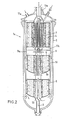
- Fig. 2 den Schnitt durch ein weiteres Ausführungsbeispiel mit drei Katalysatorbetten,
- Fig. 3 ein abgewandeltes Ausführungsbeipiel nach der Gestaltung gemäß Fig. 2,
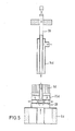
- Fig. 4 ein weiteres Ausführungsbeispiel der Erfindung sowie in
- Fig. 5 eine abgewandelte Gestaltung einer Regelung nach dem Ausführungsbeispiel gemäß Fig. 4.
- Die allgemein mit 1 bezeichnete Vorrichtung wird im wesentlichen von einem Druckbehälter 2 gebildet, in dem im dargestellten Beispiel gemäß Fig. 1 zwei Katalysatorbetten, in den Ausführungsbeispielen gemäß Fig. 2 bis 4 drei Katalysatorbetten konzentrisch zur Mittelachse 3 angeordnet sind. Das obere und erste Katalysatorbett ist mit 4 bezeichnet, das zweite mit 5 und das untere und letzte (bei den Ausführungsbeispielen gemäß Fig. 2 bis 4) mit 6.
- Im Inneren des ersten Katalysatorbettes 4 ist ein erster Wärmetauscher 7 angeordnet, wobei bei den Ausführungsbeispielen gemäß Fig. 2 bis 4 im Inneren des zweiten Katalysatorbettes 5 ein zweiter Wärmetauscher 8 angeordnet ist, wobei im letzteren Falle die Wärmetauscher 7 und 8 funktionsmäßig hintereinandergeschaltet sind. Die Katalysatoren einschließlich der Wärmetauscher sind von einer Hüllwand 9 umgeben, die so bemessen ist, daß sich zwischen der Innenfläche der Behälterwand der Hüllwand 9 ein durchgehender Ringraum 10 bildet.
- Beim Ausführungsbeispiel gemäß Fig. 1 strömt ein Kühlgas oben in die Vorrichtung 1 durch einen Stutzen 11 ein, durchströmt den Ringraum 10 und tritt unten zusammen mit dem Kreislaufgas durch einen Stutzen 12 aus. Der obere Eintrittsstutzen für das Kreislaufgas ist mit 13 bezeichnet. Konzentrisch im Inneren des Wärmetauschers 7 ist ein Rohr 14 vorgesehen, welches über einen Zuleitungsstutzen 15 von Gas zur Regelung beaufschlagbar ist.
- Dieses zentrische Rohr mündet in einer Verteilerkammer 16 für das Prozeßgas, welches bereits das erste Katalysatorbett 4 sowohl innen als auch außen den Wärmetauscher 7 und die Führungsrohre 30 durchströmt hat.
- Unterhalb des ersten Wärmetauschers 7 ist eine weitere Verteilerkammer 17 gasdicht getrennt von der Verteilerkammer 16 vorgesehen, in die das Prozeßgas nach Durchströmen von Führungsrohren 30 des Wärmetauschers 7 gelangt, um von dort dem Katalysatorbett 4 zugeführt zu werden. In diesem Bereich weist das zentrische Rohr 14 Öffnungen 18 auf, durch die wenigstens ein Teil des durch das zentrische Rohr 14 strömenden Regelgases in die Verteilerkammer 17 einströmen kann. Über eine Steuerstange 19, die im Bereich der Schlitze 18 einen mit axialen Durchbrechungen versehenen Schließkolben 20 und am unteren freien Ende ein Schließstopfen 21 trägt, läßt sich die Regelung des Steuergases und eine prozentuale Verteilung von Teilströmen des Steuergases auf die Verteilerkammer 16 und die Verteilerkammer 17 erreichen.
- Die Wirkungsweise ist dabei die folgende:
- Ist z.B. die Steuerstange 19 ganz nach oben gemäß Doppelpfeil 22 gezogen worden, so verschließt der Stopfen 21 das untere freie Ende des zentrischen Rohres 14, gleichzeitig sind die Schlitze 18 vollständig geöffnet. Das Regelgas strömt nunmehr vollständig durch die Schlitze 18 in den Raum 17, d.h. es vermischt sich mit dem Prozeßgasstrom vor dessen Durchströmen des Katalysatorbettes 4.
- Wird nun die Steuerstange 18 nach unten verfahren, öffnet der Schließstopfen 21 in dem Maße die untere Durchtrittsöffnung, in dem die Schlitze 18 verschlossen werden, so daß bei der unteren Todpunktlage die Schlitze 18 vollständig verschlossen sind, während die untere Öffnung des zentrischen Rohres 14 zur Verteilerkammer 16 vollständig geöffnet ist, so daß der gesamte Regelgasstrom sozusagen als by-pass dort zugeführt wird und sich mit dem Prozeßgasstrom mischt, der sowohl das erste Katalysatorbett als auch den Wärmetauscher 7 innen und außen durchströmt hat.
- Funktionsmäßig gleiche Teile der folgenden Ausführungsbeispiele tragen die gleiche Bezugsziffer ergänzt durch Kleinbuchstaben:
- Bei dem Ausführungsbeispiel gemäß Fig. 2 sind die Verhältnisse grundsätzlich gleich, jedoch mit der Variante, daß das Prozeßgas oben als Teilstrom zentrisch durch einen Rohrstutzen 13a eingeführt wird und ein Teil durch einen Rohrstutzen 11a als kühlendes Mantelgas, welches dann das dritte Katalysatorbett 6a von unten in dessen Mitte durch ein Steigrohr 23 durchströmt, nachfolgend den zweiten Wärmetauscher 8 und dann in die Mischkammer 17a. Die Verteilung des Steuergases ist hier wiederum in gleicher Weise gelöst, wie beim Ausführungsbeispiel gemäß Fig. 1.
- Ähnlich verhält es sich mit dem Ausführungsbeispiel gemäß Fig. 3, hier wird allerdings das Kreislaufgas in drei Teilströmen zugeführt durch einen oberen Zuführstutzen 13b, einen oberen ersten Mantelgaszuführstutzen 11b sowie zusätzlich durch einen unteren Mantelgaszuführstutzen 24. Hier werden durch radiale Sammelleitungen 25 die Mantelgasströme von oben und unten unterhalb des zweiten Wärmetauschers 8b in einer gemeinsamen Vorkammer 26 gesammelt und nach oben geleitet. Die Zumischung von Regelgas ist hier wiederum gleich gestaltet.
- Ein abgewandeltes Ausführungsbeispiel der Steuerung besteht nach Fig. 4 darin, daß dort die Steuerstange 19c den ersten Wärmetauscher 7c und den zweiten Wärmetauscher 8c vollständig durchsetzt und die Zufuhr des von unten über die zentrische Zuführleitung 23c kommenden Mantelgases zu der Vorkammer 26c des zweiten Wärmetauschers 8c regelt. Hier ist z.B. ein Hohlzylindersperrelement vorgesehen, welches das Bezugszeichen 27 trägt. Wird es nach oben angehoben, so gibt es wenigstens einem Teilstrom die Möglichkeit, seitlich auszutreten und sich direkt dem Prozeßgasstrom zuzumischen, der dann das untere und dritte Katalysatorbett 6c beaufschlagt. Ist die Regelstange nach unten verschoben, so läßt der Hohlzylinder 27 nur das Durchströmen des Mantelgases nach oben zu, eine Zumischung ist dann nicht möglich.
- Schließlich zeigt Fig. 5 die Möglichkeit, mehrere Regelgasströme zuzuführen. Dabei ist diese Steuerungsmöglichkeit nur im Prinzip dargestellt. Das zentrische, mit 14d bezeichnete Rohr wird von einem weiteren zentrischen Rohr 28 durchsetzt, und zwar soweit, daß dieses im Bereich der ersten Vorkammer 26d des zweiten Wärmetauschers 8d endet. Hierbei sind radiale Verteilerleitungen 29 vorgesehen, die es ermöglichen, Regelgas demjenigen Gasstrom zuzumischen, der den zweiten Wärmetauscher 8d verläßt und dem dritten Katalysatorbett 6d zugeführt wird.
- Natürlich sind die beschriebenen Ausführungsbeispiele der Erfindung noch in vielfacher Hinsicht abzuändern, ohne den Grundgedanken zu verlassen. So kann die Aufschlagregelung der einzelnen Vorkammern durch Kolben/Zylinderelemente z.B. auch bei dem Ausführungsbeispiel gemäß Fig. 5 in Kombination bei den mit den zentrischen Rohren 28 und 14d vorgesehen sein u. dgl. mehr.
Claims (8)
dadurch gekennzeichnet,
daß das zentrische Rohr (14) zur Temperaturregelung als Regelgaszuführrohr den Wärmetauscher (4 bzw. 5 bzw. 6) vollständig durchsetzt und an seinem unteren Ende mit regelbaren Auslässen (18) zur wenigstens teilweisen Zumischung des Regelgases in den Prozeßgasstrom vor dessen Durchströmen des Katalysatorbettes (4) und/oder zur Zumischung des Regelgasstromes in den Prozeßgasstrom nach dessen Durchströmen des Katalysatorbettes (4) und des Wärmetauschers (7) versehen ist.
dadurch gekennzeichnet,
daß die den Wärmetauscher (7) durchsetzenden Führungsrohre (30) für das Prozeßgas das zentrische, regelbare Rohr (14 oder 28) im Abstand hierzu umgeben.
dadurch gekennzeichnet,
daß die Verteilungsöffnungen des zentrischen Rohres (14) in Abhängigkeit zueinander synchron steuerbar ausgebildet sind.
dadurch gekennzeichnet,
daß zur Durchsatzregelung das zentrische Rohr (14) mit über einen mit axialen Durchbrechungen versehenen Kolben (20) verschließbare Öffnungen am unteren Ende versehen ist, wobei diese Öffnungen in einen Strömungskanal (16 bzw. 17) für das Kreislaufgas münden.
dadurch gekennzeichnet,
daß das stirnseitige untere Ende über ein mit dem Zylinder (20) gekoppeltes Dichtelement (21) vollständig abdichtbar ausgebildet ist.
dadurch gekennzeichnet,
daß bei mehr als zwei Katalysatorbetten (4-6) mit Wärmetauschern (7,8) das zentrische Rohr (28) und/oder die Betätigung (19c) der regelbaren Auslässe wenigstens einen weiteren Wärmetauscher (8) durchsetzen.
dadurch gekennzeichnet,
daß bei einer zentrischen Zuströmung (23) von den Behältermantel (2) kühlendem, kaltem Prozeßgas von unten durch ein drittes Katalysatorbett (6) in die Vorkammer (26) des zweiten Wärmetauschers (8) ein Regelorgan (27) vorgesehen ist, das die Zumischung wenigstens eines Teiles des kälteren Mantelgases in das Prozeßgas vor Eintritt in das dritte Katalysatorbett (6c) ermöglicht.
dadurch gekennzeichnet,
daß das erste zentrische Rohr (14d) von einem zweiten zentrischen Rohr (28) durchsetzt wird, wobei das zweite zentrische Rohr (28) bis unter den folgenden Wärmetauscher (8) geführt ist und der Zumischung von Regelgas in den Prozeßgasstrom vor dem dritten Katalysatorbett (6) dient.
Priority Applications (1)
| Application Number | Priority Date | Filing Date | Title |
|---|---|---|---|
| AT87117925T ATE72423T1 (de) | 1986-12-22 | 1987-12-04 | Vorrichtung zum regeln insbesondere eines ammoniakkonverters. |
Applications Claiming Priority (2)
| Application Number | Priority Date | Filing Date | Title |
|---|---|---|---|
| DE3643856 | 1986-12-22 | ||
| DE19863643856 DE3643856A1 (de) | 1986-12-22 | 1986-12-22 | Vorrichtung zum regeln insbesondere eines ammoniakkonverters |
Publications (3)
| Publication Number | Publication Date |
|---|---|
| EP0273231A2 true EP0273231A2 (de) | 1988-07-06 |
| EP0273231A3 EP0273231A3 (en) | 1988-10-05 |
| EP0273231B1 EP0273231B1 (de) | 1992-02-05 |
Family
ID=6316843
Family Applications (1)
| Application Number | Title | Priority Date | Filing Date |
|---|---|---|---|
| EP87117925A Expired - Lifetime EP0273231B1 (de) | 1986-12-22 | 1987-12-04 | Vorrichtung zum Regeln insbesondere eines Ammoniakkonverters |
Country Status (12)
| Country | Link |
|---|---|
| EP (1) | EP0273231B1 (de) |
| JP (1) | JPS63248431A (de) |
| CN (1) | CN1013664B (de) |
| AT (1) | ATE72423T1 (de) |
| AU (1) | AU602744B2 (de) |
| CA (1) | CA1287480C (de) |
| DE (2) | DE3643856A1 (de) |
| DK (1) | DK166772B1 (de) |
| ES (1) | ES2029260T3 (de) |
| FI (1) | FI875417A7 (de) |
| NO (1) | NO168020C (de) |
| ZA (1) | ZA879320B (de) |
Cited By (4)
| Publication number | Priority date | Publication date | Assignee | Title |
|---|---|---|---|---|
| EP0345505A3 (de) * | 1988-06-08 | 1990-03-07 | Uhde GmbH | Vorrichtung zur Durchführung exothermer, katalytischer Gasreaktionen für die Ammoniak- oder Methanol-Synthese |
| WO1992005112A1 (en) * | 1990-09-24 | 1992-04-02 | C.F. Braun Inc. | High conversion ammonia synthesis |
| EP1419813A1 (de) * | 2002-11-15 | 2004-05-19 | Kellog Brown & Root, Inc. | Vorrichtung zur Ammoniak Herstellung |
| US7981271B2 (en) * | 2003-01-29 | 2011-07-19 | Methanol Casale S.A. | Pseudo-isothermal radial reactor |
Families Citing this family (5)
| Publication number | Priority date | Publication date | Assignee | Title |
|---|---|---|---|---|
| DE3710004A1 (de) * | 1987-03-26 | 1988-10-06 | Uhde Gmbh | Vorrichtung zur katalytischen behandlung von stickstoff und wasserstoff |
| US7371361B2 (en) * | 2004-11-03 | 2008-05-13 | Kellogg Brown & Root Llc | Maximum reaction rate converter system for exothermic reactions |
| US7867465B2 (en) * | 2008-05-29 | 2011-01-11 | Kellogg Brown & Root Llc | Cold wall horizontal ammonia converter |
| BR112013028447A2 (pt) * | 2011-06-16 | 2018-06-19 | Haldor Topsoe As | método para executar reações catalíticas exotérmicas e reator para utilização no método |
| CN105621454A (zh) * | 2016-02-25 | 2016-06-01 | 山东奥能电力科技有限公司 | 一体化液氨消纳转化装置 |
Family Cites Families (8)
| Publication number | Priority date | Publication date | Assignee | Title |
|---|---|---|---|---|
| DE1715928U (de) * | 1954-09-18 | 1956-02-02 | Adolf Dipl Ing Schild | Waermeaustauscher mit kuehlwassermengenregler. |
| US3852147A (en) * | 1972-04-24 | 1974-12-03 | W Wilson | Heat exchanger |
| GB1574723A (en) * | 1976-03-10 | 1980-09-10 | Haldor Topsoe As | Apparatus for the synthesis of ammonia |
| GB1565824A (en) * | 1976-11-15 | 1980-04-23 | Ici Ltd | Exothermic process and apparatus therefor |
| CH646618A5 (it) * | 1981-03-26 | 1984-12-14 | Ammonia Casale Sa | Reattore per sintesi eterogenee catalitiche. |
| FR2539524B1 (fr) * | 1983-01-17 | 1986-08-22 | Azote & Prod Chim | Procede de regulation des temperatures de fonctionnement d'un reacteur de synthese et equipement interne de mise en oeuvre |
| DE3343114C2 (de) * | 1983-11-29 | 1985-11-07 | Uhde Gmbh, 4600 Dortmund | Vorrichtung zur Durchführung exothermer, katalytischer Gasreaktionen für die Ammoniak- oder Methanol-Synthese |
| JPS60225632A (ja) * | 1984-04-23 | 1985-11-09 | Mitsubishi Heavy Ind Ltd | 反応器 |
-
1986
- 1986-12-22 DE DE19863643856 patent/DE3643856A1/de active Granted
-
1987
- 1987-12-04 AT AT87117925T patent/ATE72423T1/de not_active IP Right Cessation
- 1987-12-04 DE DE8787117925T patent/DE3776634D1/de not_active Expired - Fee Related
- 1987-12-04 ES ES198787117925T patent/ES2029260T3/es not_active Expired - Lifetime
- 1987-12-04 EP EP87117925A patent/EP0273231B1/de not_active Expired - Lifetime
- 1987-12-09 DK DK647587A patent/DK166772B1/da not_active IP Right Cessation
- 1987-12-09 FI FI875417A patent/FI875417A7/fi not_active Application Discontinuation
- 1987-12-09 NO NO875137A patent/NO168020C/no unknown
- 1987-12-11 ZA ZA879320A patent/ZA879320B/xx unknown
- 1987-12-15 CA CA000554318A patent/CA1287480C/en not_active Expired - Fee Related
- 1987-12-16 JP JP62316364A patent/JPS63248431A/ja active Pending
- 1987-12-17 AU AU82899/87A patent/AU602744B2/en not_active Ceased
- 1987-12-22 CN CN87108165A patent/CN1013664B/zh not_active Expired
Cited By (5)
| Publication number | Priority date | Publication date | Assignee | Title |
|---|---|---|---|---|
| EP0345505A3 (de) * | 1988-06-08 | 1990-03-07 | Uhde GmbH | Vorrichtung zur Durchführung exothermer, katalytischer Gasreaktionen für die Ammoniak- oder Methanol-Synthese |
| WO1992005112A1 (en) * | 1990-09-24 | 1992-04-02 | C.F. Braun Inc. | High conversion ammonia synthesis |
| US5352428A (en) * | 1990-09-24 | 1994-10-04 | C.F. Braun, Inc. | High conversion ammonia synthesis |
| EP1419813A1 (de) * | 2002-11-15 | 2004-05-19 | Kellog Brown & Root, Inc. | Vorrichtung zur Ammoniak Herstellung |
| US7981271B2 (en) * | 2003-01-29 | 2011-07-19 | Methanol Casale S.A. | Pseudo-isothermal radial reactor |
Also Published As
| Publication number | Publication date |
|---|---|
| EP0273231B1 (de) | 1992-02-05 |
| DK647587D0 (da) | 1987-12-09 |
| NO168020C (no) | 1992-01-08 |
| DK166772B1 (da) | 1993-07-12 |
| EP0273231A3 (en) | 1988-10-05 |
| ATE72423T1 (de) | 1992-02-15 |
| NO168020B (no) | 1991-09-30 |
| CA1287480C (en) | 1991-08-13 |
| NO875137D0 (no) | 1987-12-09 |
| DK647587A (da) | 1988-06-23 |
| DE3643856A1 (de) | 1988-06-30 |
| DE3776634D1 (de) | 1992-03-19 |
| AU602744B2 (en) | 1990-10-25 |
| CN1013664B (zh) | 1991-08-28 |
| ES2029260T3 (es) | 1992-08-01 |
| NO875137L (no) | 1988-06-23 |
| DE3643856C2 (de) | 1989-10-12 |
| CN87108165A (zh) | 1988-08-03 |
| AU8289987A (en) | 1988-06-23 |
| ZA879320B (en) | 1988-06-15 |
| FI875417A0 (fi) | 1987-12-09 |
| FI875417A7 (fi) | 1988-06-23 |
| JPS63248431A (ja) | 1988-10-14 |
Similar Documents
| Publication | Publication Date | Title |
|---|---|---|
| DE3146778C2 (de) | ||
| EP0079510B1 (de) | Mischkopf | |
| DE3413552A1 (de) | Brause | |
| DE2754559A1 (de) | Heissdampfkuehler | |
| EP0273231B1 (de) | Vorrichtung zum Regeln insbesondere eines Ammoniakkonverters | |
| DE102009036537B3 (de) | Vorrichtung und Verfahren zur Emulgierung von Flüssigkeiten | |
| DE2754477C3 (de) | In einem Schüttgutbehandlungsbunker angeordneter Gasverteiler | |
| EP0357907B1 (de) | Wärmetauscher | |
| DE2301644B1 (de) | Vorrichtung zur herstellung eines homogenen gasgemisches | |
| DE19543960C2 (de) | Sprüharm für eine Beschichtungsvorrichtung | |
| EP0272448B1 (de) | Vorrichtung als NH3-Reaktor | |
| DE2836345C2 (de) | Anlage zur Rußherstellung | |
| EP0285757A1 (de) | Vorrichtung zur katalytischen Behandlung von Stickstoff und Wasserstoff | |
| DE102015221504A1 (de) | Mischbatterie zum Mischen von zwei Wasserströmen unterschiedlicher Temperatur | |
| DE102007027881B4 (de) | Verfahren und Vorrichtung zur Mischung von Gasen | |
| EP0473870B1 (de) | Reformer, insbesondere autothermer Sekundärreformer | |
| DE2855499A1 (de) | Aufblaslanze | |
| DE1542215C (de) | Hochdruckreaktor mit Wärmeaustauscher und Katalysatorbett | |
| DE1442840A1 (de) | Verfahren und Vorrichtung zur Beaufschlagung der Rohre von Roehrenoefen | |
| DE1767356C3 (de) | Vorrichtung zur Durchführung exothermer katalytischer Reaktionen | |
| DE681545C (de) | Thermostatische Mischvorrichtung | |
| DE1542215B2 (de) | Hochdruckreaktor mit waermeaustauscher und katalysatorbett | |
| DE2161144A1 (de) | Mischarmatur fuer badezimmer | |
| DE1956230A1 (de) | Verfahren zum Betrieb batterieweise angeordneter waagerechter Koksofenkammern | |
| DE533106C (de) | Verfahren zur Regulierung der Reaktionstemperatur bei Gasreaktionen |
Legal Events
| Date | Code | Title | Description |
|---|---|---|---|
| PUAI | Public reference made under article 153(3) epc to a published international application that has entered the european phase |
Free format text: ORIGINAL CODE: 0009012 |
|
| AK | Designated contracting states |
Kind code of ref document: A2 Designated state(s): AT BE DE ES FR GB IT NL |
|
| PUAL | Search report despatched |
Free format text: ORIGINAL CODE: 0009013 |
|
| RHK1 | Main classification (correction) |
Ipc: C01C 1/04 |
|
| AK | Designated contracting states |
Kind code of ref document: A3 Designated state(s): AT BE DE ES FR GB IT NL |
|
| 17P | Request for examination filed |
Effective date: 19880908 |
|
| 17Q | First examination report despatched |
Effective date: 19900802 |
|
| GRAA | (expected) grant |
Free format text: ORIGINAL CODE: 0009210 |
|
| AK | Designated contracting states |
Kind code of ref document: B1 Designated state(s): AT BE DE ES FR GB IT NL |
|
| REF | Corresponds to: |
Ref document number: 72423 Country of ref document: AT Date of ref document: 19920215 Kind code of ref document: T |
|
| REF | Corresponds to: |
Ref document number: 3776634 Country of ref document: DE Date of ref document: 19920319 |
|
| ITF | It: translation for a ep patent filed | ||
| ET | Fr: translation filed | ||
| GBT | Gb: translation of ep patent filed (gb section 77(6)(a)/1977) | ||
| REG | Reference to a national code |
Ref country code: ES Ref legal event code: FG2A Ref document number: 2029260 Country of ref document: ES Kind code of ref document: T3 |
|
| PGFP | Annual fee paid to national office [announced via postgrant information from national office to epo] |
Ref country code: DE Payment date: 19921114 Year of fee payment: 6 |
|
| PGFP | Annual fee paid to national office [announced via postgrant information from national office to epo] |
Ref country code: FR Payment date: 19921117 Year of fee payment: 6 |
|
| PGFP | Annual fee paid to national office [announced via postgrant information from national office to epo] |
Ref country code: BE Payment date: 19921118 Year of fee payment: 6 |
|
| PGFP | Annual fee paid to national office [announced via postgrant information from national office to epo] |
Ref country code: GB Payment date: 19921124 Year of fee payment: 6 |
|
| PGFP | Annual fee paid to national office [announced via postgrant information from national office to epo] |
Ref country code: ES Payment date: 19921127 Year of fee payment: 6 |
|
| PLBE | No opposition filed within time limit |
Free format text: ORIGINAL CODE: 0009261 |
|
| STAA | Information on the status of an ep patent application or granted ep patent |
Free format text: STATUS: NO OPPOSITION FILED WITHIN TIME LIMIT |
|
| PGFP | Annual fee paid to national office [announced via postgrant information from national office to epo] |
Ref country code: AT Payment date: 19921229 Year of fee payment: 6 |
|
| PGFP | Annual fee paid to national office [announced via postgrant information from national office to epo] |
Ref country code: NL Payment date: 19921231 Year of fee payment: 6 |
|
| 26N | No opposition filed | ||
| PG25 | Lapsed in a contracting state [announced via postgrant information from national office to epo] |
Ref country code: GB Effective date: 19931204 Ref country code: AT Effective date: 19931204 |
|
| PG25 | Lapsed in a contracting state [announced via postgrant information from national office to epo] |
Ref country code: ES Free format text: LAPSE BECAUSE OF EXPIRATION OF PROTECTION Effective date: 19931207 |
|
| PG25 | Lapsed in a contracting state [announced via postgrant information from national office to epo] |
Ref country code: BE Effective date: 19931231 |
|
| BERE | Be: lapsed |
Owner name: UHDE G.M.B.H. Effective date: 19931231 |
|
| PG25 | Lapsed in a contracting state [announced via postgrant information from national office to epo] |
Ref country code: NL Effective date: 19940701 |
|
| GBPC | Gb: european patent ceased through non-payment of renewal fee |
Effective date: 19931204 |
|
| NLV4 | Nl: lapsed or anulled due to non-payment of the annual fee | ||
| PG25 | Lapsed in a contracting state [announced via postgrant information from national office to epo] |
Ref country code: FR Effective date: 19940831 |
|
| PG25 | Lapsed in a contracting state [announced via postgrant information from national office to epo] |
Ref country code: DE Effective date: 19940901 |
|
| REG | Reference to a national code |
Ref country code: FR Ref legal event code: ST |
|
| REG | Reference to a national code |
Ref country code: ES Ref legal event code: FD2A Effective date: 20010201 |
|
| PG25 | Lapsed in a contracting state [announced via postgrant information from national office to epo] |
Ref country code: IT Free format text: LAPSE BECAUSE OF NON-PAYMENT OF DUE FEES;WARNING: LAPSES OF ITALIAN PATENTS WITH EFFECTIVE DATE BEFORE 2007 MAY HAVE OCCURRED AT ANY TIME BEFORE 2007. THE CORRECT EFFECTIVE DATE MAY BE DIFFERENT FROM THE ONE RECORDED. Effective date: 20051204 |