EP0273324A1 - Curseur de fermeture à glissière à verrouillage automatique - Google Patents
Curseur de fermeture à glissière à verrouillage automatique Download PDFInfo
- Publication number
- EP0273324A1 EP0273324A1 EP87118875A EP87118875A EP0273324A1 EP 0273324 A1 EP0273324 A1 EP 0273324A1 EP 87118875 A EP87118875 A EP 87118875A EP 87118875 A EP87118875 A EP 87118875A EP 0273324 A1 EP0273324 A1 EP 0273324A1
- Authority
- EP
- European Patent Office
- Prior art keywords
- pull tab
- housing
- spindle portion
- carrier
- large windows
- Prior art date
- Legal status (The legal status is an assumption and is not a legal conclusion. Google has not performed a legal analysis and makes no representation as to the accuracy of the status listed.)
- Granted
Links
Images


Classifications
-
- A—HUMAN NECESSITIES
- A44—HABERDASHERY; JEWELLERY
- A44B—BUTTONS, PINS, BUCKLES, SLIDE FASTENERS, OR THE LIKE
- A44B19/00—Slide fasteners
- A44B19/24—Details
- A44B19/26—Sliders
- A44B19/30—Sliders with means for locking in position
-
- A—HUMAN NECESSITIES
- A44—HABERDASHERY; JEWELLERY
- A44B—BUTTONS, PINS, BUCKLES, SLIDE FASTENERS, OR THE LIKE
- A44B19/00—Slide fasteners
- A44B19/24—Details
- A44B19/26—Sliders
-
- A—HUMAN NECESSITIES
- A44—HABERDASHERY; JEWELLERY
- A44B—BUTTONS, PINS, BUCKLES, SLIDE FASTENERS, OR THE LIKE
- A44B19/00—Slide fasteners
- A44B19/24—Details
- A44B19/26—Sliders
- A44B19/30—Sliders with means for locking in position
- A44B19/308—Sliders with means for locking in position in the form of a spring-actuated locking member actuated by the pull member
-
- Y—GENERAL TAGGING OF NEW TECHNOLOGICAL DEVELOPMENTS; GENERAL TAGGING OF CROSS-SECTIONAL TECHNOLOGIES SPANNING OVER SEVERAL SECTIONS OF THE IPC; TECHNICAL SUBJECTS COVERED BY FORMER USPC CROSS-REFERENCE ART COLLECTIONS [XRACs] AND DIGESTS
- Y10—TECHNICAL SUBJECTS COVERED BY FORMER USPC
- Y10T—TECHNICAL SUBJECTS COVERED BY FORMER US CLASSIFICATION
- Y10T24/00—Buckles, buttons, clasps, etc.
- Y10T24/25—Zipper or required component thereof
- Y10T24/2561—Slider having specific configuration, construction, adaptation, or material
- Y10T24/2566—Slider having specific configuration, construction, adaptation, or material including position locking-means attached thereto
- Y10T24/2568—Protrusion on pull tab directly engaging interlocking surfaces
-
- Y—GENERAL TAGGING OF NEW TECHNOLOGICAL DEVELOPMENTS; GENERAL TAGGING OF CROSS-SECTIONAL TECHNOLOGIES SPANNING OVER SEVERAL SECTIONS OF THE IPC; TECHNICAL SUBJECTS COVERED BY FORMER USPC CROSS-REFERENCE ART COLLECTIONS [XRACs] AND DIGESTS
- Y10—TECHNICAL SUBJECTS COVERED BY FORMER USPC
- Y10T—TECHNICAL SUBJECTS COVERED BY FORMER US CLASSIFICATION
- Y10T24/00—Buckles, buttons, clasps, etc.
- Y10T24/25—Zipper or required component thereof
- Y10T24/2561—Slider having specific configuration, construction, adaptation, or material
- Y10T24/2566—Slider having specific configuration, construction, adaptation, or material including position locking-means attached thereto
- Y10T24/257—Slider having specific configuration, construction, adaptation, or material including position locking-means attached thereto having surface engaging element shifted by reorientation of pull tab
- Y10T24/2571—Resilient or spring biased element
-
- Y—GENERAL TAGGING OF NEW TECHNOLOGICAL DEVELOPMENTS; GENERAL TAGGING OF CROSS-SECTIONAL TECHNOLOGIES SPANNING OVER SEVERAL SECTIONS OF THE IPC; TECHNICAL SUBJECTS COVERED BY FORMER USPC CROSS-REFERENCE ART COLLECTIONS [XRACs] AND DIGESTS
- Y10—TECHNICAL SUBJECTS COVERED BY FORMER USPC
- Y10T—TECHNICAL SUBJECTS COVERED BY FORMER US CLASSIFICATION
- Y10T24/00—Buckles, buttons, clasps, etc.
- Y10T24/25—Zipper or required component thereof
- Y10T24/2561—Slider having specific configuration, construction, adaptation, or material
- Y10T24/2586—Slider having specific configuration, construction, adaptation, or material including pull tab attaching means
Definitions
- This invention relates to an automatically locking slider for slide fasteners.
- a variety of slide fasteners are known which are equipped with means for automatically locking the slider members in position against accidental movement.
- Typical examples of such automatically locking sliders are disclosed for example in Japanese Utility Model Publication Nos. 57-58966, 58-3527 and 61-27449.
- the prior art automatically locking sliders were however provided with pull tabs which had already been built in during assembling of the slider components. Such built-in pull tabs were therefore unable to be replaced once the sliders were finished as products.
- the present invention seeks to provide an automatically locking slider for a slide fastener which is constructed such that a pull tab can be mounted in operative position on the slider after the latter is assembled or can be removed for replacement with another at the option of the user.
- an automatically locking slider for a slide fastener having a pair of rows of coupling elements comprising: a slider body including upper and lower wings joined at their front ends by a diamond so as to define a guide channel for the passage of the rows of coupling elements; a housing having in its opposite side walls a pair of transversely aligned large windows and secured to said upper wing; a locking member having a locking prong and pivotally accomodated in said housing, said prong being normally urged into the guide channel to lock the slider in position against displacement with respect to the rows of coupling elements, said locking member further having a bay substantially aligned with said large windows of said housing; a pull tab having a spindle portion to be pivotally received in said large windows and said bay; and a pull tab carrier slidably mounted on said upper wing and movable between a closed position to prevent said spindle portion of said pull tab from being removed from said large windows, and an open position to allow said spindle portion of said pull tab to move into
- an automatically locking type of slider 10 which comprises a slider body 11 including a flanged upper wing 12 and a flanged lower wing 13 joined at their one ends by a diamond 14 so as to define a Y-shaped guide channel 15 therebetween for the passage of a pair of coupling element rows of a slide fastener (not shown).
- the upper wing 12 has a U-shaped wall 16 defining an aperture 17 communicatng with the guide channel 15 and adapted to receive a locking prong later described.
- the upper wing 12 further has a pair of laterally spaced support lugs 18 extending on opposite sides of the aperture 17 and each having a pin hole 19.
- a peripheral groove 20 is formed in the upper wing 12 around the pair of lugs 18 in the region of the diamond 14 and is adapted to fixedly receive a wide flange portion 21a of a cap or housing 21.
- the housing 21 has pin holes 21b registering with the pin holes 19 of the lugs 18.
- the housing 21 has its rear end (opposite to the diamond 14) cut away to provide a clearance or opening 21c for the passage of a pull tab 26 later described.
- a first small window 21d and a second large window 21e are formed transversely across the sidewalls of the housing 21 and are separated by a projection 21f.
- a locking member 22 includes opposed arms 22a and 22b defining therebetween a bay 22c and a locking prong 22d extending downwardly from the arm 22b with a hole 22e at an opposite end to the prong 22d.
- the locking member 22 is interposed between the support lugs 18 and pivotally connected thereto by a pin 23 which extends through the holes 19, 21b and 22e thereby connecting the housing 21 and the locking member 22 integrally with the slider body 11.
- a spring 24 is accommodated in a cavity 24 ⁇ formed in the diamond 14 and connected to the locking member 22 so as to normally urge the locking prong 22d into the guide channel 15 as shown in Figure 2.
- Designated at 25 is a pull tab carrier in the form of a rectangular block which has an abutment end wall 25a and a pair of spaced side posts 25b defining therebetween a cavity 25c which is substantially U-shaped as viewed in plan and which is dimensioned to fit around the peripheral wall 16 in the upper wing 12 of the slider body 11.
- Internally contiguous to each side post 25b is an arcuate recess 25e adapted to receive a spindle portion 26a of the pull tab 26, and externally contiguous to each side post 25b is a sloping end wall 25f.
- the pull tab carrier 25 is provided with a rail 25g secured to each of its side walls and slidably engageable in an elongated groove 27 formed in the upper wing 12 and extending longitudinally up to each of the support lugs 18.
- the carrier 25 is normally urged by a spring 28 to move outwardly but upon mounting the carrier 25 in place on the slider body 11 as shown in Figure 2 it is blocked from such outward movement by a pair of stops 29 which are initially located outside of the grooves 27 but will, after the carrier 25 is assembled, be deformed to merge with and fill in the grooves 27.
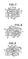
- the carrier 25 is moved by the spindle 26a against the tension of the spring 28 again to the position of Figure 3 wherein the spindle 26a enters into the bay 22c of the locking member 22 as shown in Figure 5.
- the pull tab 26 is then lifted with its spindle 26a disengaged from the recesses 25e to allow the carrier 25 to return again to the original position as shown in Figure 6 and at the same time urging the locking member 22 to rotate counterclockwise against the tension of the spring 24 until the locking prong 22d is fully retracted through the aperture 17 after being disengaged from fastener elements (not shown).
- Figure 7 shows a modified slider 10A in which the housing 21 has only a single large window 21e contiguous to a rear end of the housing 21 so that both the large window 21e and the opening 21c are simultaneously closed and opened only by the pair of side posts 25b of the pull tab carrier 25.
- this modified arrangement it is possible to reduce the entire length of the housing 21 to some extent, as compared with the previous embodiment of Figures 1 to 6.
- Figure 8 shows another modified slider 10B in which the locking member 22 has at one end adjacent to the diamond 14 a pivot projection of semi-circular cross section rockably received in a recess 23B of generally semi-circular cross section formed in the top surface of the upper wing 12 and is pivotable about the pivot projection 23A.
- the pivot projection 23A serves as the pin 23 of the previous embodiment.
- a leaf spring 24A is a substitute for the coil spring 24 of the previous embodiment.
- the leaf spring 24A is disposed between the housing 21 and the locking member 22 to normally urge the latter downwardly.
Landscapes
- Slide Fasteners (AREA)
- Packaging Of Annular Or Rod-Shaped Articles, Wearing Apparel, Cassettes, Or The Like (AREA)
- Replacing, Conveying, And Pick-Finding For Filamentary Materials (AREA)
Applications Claiming Priority (2)
| Application Number | Priority Date | Filing Date | Title |
|---|---|---|---|
| JP1986195521U JPH0432974Y2 (fr) | 1986-12-19 | 1986-12-19 | |
| JP195521/86 | 1986-12-19 |
Publications (2)
| Publication Number | Publication Date |
|---|---|
| EP0273324A1 true EP0273324A1 (fr) | 1988-07-06 |
| EP0273324B1 EP0273324B1 (fr) | 1990-07-04 |
Family
ID=16342470
Family Applications (1)
| Application Number | Title | Priority Date | Filing Date |
|---|---|---|---|
| EP87118875A Expired - Lifetime EP0273324B1 (fr) | 1986-12-19 | 1987-12-18 | Curseur de fermeture à glissière à verrouillage automatique |
Country Status (13)
| Country | Link |
|---|---|
| US (1) | US4829638A (fr) |
| EP (1) | EP0273324B1 (fr) |
| JP (1) | JPH0432974Y2 (fr) |
| KR (1) | KR900004143Y1 (fr) |
| AU (1) | AU576709B2 (fr) |
| BR (1) | BR8707045A (fr) |
| CA (1) | CA1288582C (fr) |
| DE (1) | DE3763584D1 (fr) |
| ES (1) | ES2015564B3 (fr) |
| HK (1) | HK61593A (fr) |
| MY (1) | MY101531A (fr) |
| SG (1) | SG39993G (fr) |
| ZA (1) | ZA879521B (fr) |
Cited By (5)
| Publication number | Priority date | Publication date | Assignee | Title |
|---|---|---|---|---|
| EP0743024A3 (fr) * | 1995-05-19 | 1998-05-20 | Ykk Corporation | Curseur à verrouillage automatique pour fermeture à glissière du type masqué |
| GB2395749A (en) * | 2002-11-26 | 2004-06-02 | Roger Chun Yen Chung | Zip slider where pull tab can be attached later |
| EP1541051A1 (fr) * | 2003-12-10 | 2005-06-15 | Ykk Corporation | Curseur de fermeture à glissière avec mécanisme d'arrêt automatique |
| EP1987730A1 (fr) * | 2007-03-16 | 2008-11-05 | YKK Corporation | Glisseur à attache coulissante |
| US9232834B2 (en) | 2010-09-24 | 2016-01-12 | Ykk Corporation | Slider for slide fastener with automatic stopper |
Families Citing this family (33)
| Publication number | Priority date | Publication date | Assignee | Title |
|---|---|---|---|---|
| JPH0432971Y2 (fr) * | 1986-12-19 | 1992-08-07 | ||
| CA2000260C (fr) * | 1988-05-20 | 1996-01-09 | Kiyoyasu Wake | Dispositif de verrouillage a cadran pour fermeture a glissiere |
| US5255418A (en) * | 1992-11-10 | 1993-10-26 | Chen Shih Chung | Automatically locking slider for concealed zipper |
| JP2528168Y2 (ja) * | 1993-09-08 | 1997-03-05 | 株式会社東京エンゼル本社 | 介護用衣類のスライドファスナー |
| JP3580337B2 (ja) * | 1997-02-28 | 2004-10-20 | Ykk株式会社 | 隠しスライドファスナー用スライダー |
| JP3611699B2 (ja) * | 1997-05-02 | 2005-01-19 | Ykk株式会社 | 引手後付けタイプのスライドファスナー用スライダー |
| JP3589438B2 (ja) * | 1997-05-16 | 2004-11-17 | Ykk株式会社 | スライドファスナー用スライダー |
| JP3599617B2 (ja) * | 1999-10-29 | 2004-12-08 | Ykk株式会社 | スライドファスナー用スライダーの引手 |
| US6685532B1 (en) * | 2002-10-16 | 2004-02-03 | Mclean Gerald J. | Plush assembly and method for stuffing same |
| CN100553514C (zh) * | 2004-11-16 | 2009-10-28 | 瑞伊有限公司 | 具有可换拉片的拉链的拉头 |
| WO2007111585A1 (fr) * | 2006-03-27 | 2007-10-04 | Ideal Fastener Corporation | Corps de curseur de fermeture à glissière pour tirette amovible |
| EP2101641A2 (fr) * | 2006-12-07 | 2009-09-23 | Philometron, Inc. | Plateforme pour la détection de teneur en tissu et/ou de changements structurels avec commande en circuit fermé dans des organismes mammifères |
| JP2008161246A (ja) | 2006-12-27 | 2008-07-17 | Ykk Corp | ばね性を備えた部材及びこれを使用した製品 |
| CN102076239B (zh) * | 2008-11-20 | 2012-12-19 | Ykk株式会社 | 拉攀能够装拆的滑动拉链用拉头 |
| US8122573B2 (en) * | 2009-01-07 | 2012-02-28 | Ykk Corporation | Thin slider |
| EP2391236B1 (fr) * | 2009-01-30 | 2015-03-11 | Columbia Sportswear North America, Inc. | Dispositif de fermeture coulissant anti-accrochage |
| CN104323542B (zh) * | 2009-11-17 | 2017-01-18 | Ykk株式会社 | 拉链用拉头 |
| CN102548447B (zh) * | 2009-11-17 | 2015-04-01 | Ykk株式会社 | 拉链用拉头 |
| CN102258236B (zh) * | 2010-05-26 | 2014-09-10 | 福建浔兴拉链科技股份有限公司 | 自锁式拉链头 |
| US8453301B1 (en) * | 2010-07-22 | 2013-06-04 | Patty McCoy | Zipper pull tab retention device |
| CN102450789B (zh) * | 2010-10-20 | 2015-06-03 | 福建浔兴拉链科技股份有限公司 | 拉链滑块及使用该拉链滑块的拉链头 |
| EP2698073B1 (fr) * | 2011-04-15 | 2016-09-07 | YKK Corporation | Curseur pour fermeture à glissière |
| JP5592563B2 (ja) * | 2011-05-12 | 2014-09-17 | Ykk株式会社 | スライドファスナー用スライダー |
| US20140123445A1 (en) * | 2011-06-21 | 2014-05-08 | Ji Ong Jung | Automatic locking slider for slide fastener |
| TWI489955B (zh) * | 2012-05-29 | 2015-07-01 | Chung Chwan Entpr Co Ltd | 可換拉片的拉頭結構及其拉片更換方法 |
| CN103564996B (zh) * | 2012-07-24 | 2017-09-05 | Ykk株式会社 | 一种拉链拉头、使用该拉链拉头的拉链及使用该拉链的物品 |
| CN103564995B (zh) * | 2012-07-24 | 2017-04-26 | Ykk株式会社 | 一种拉链拉头、使用该拉链拉头的拉链及使用该拉链的物品 |
| JP6021936B2 (ja) * | 2012-11-12 | 2016-11-09 | Ykk株式会社 | スライドファスナー用の引手後付けスライダー |
| CN104812264B (zh) * | 2012-11-26 | 2017-06-20 | Ykk株式会社 | 拉链用拉头 |
| GB2514215A (en) * | 2013-03-01 | 2014-11-19 | Coats Ltd J & P | Zip fastener |
| EP2952115A1 (fr) * | 2014-06-04 | 2015-12-09 | Riri Sa | Curseur pour fermeture à glissière |
| WO2019150227A1 (fr) | 2018-02-02 | 2019-08-08 | Talon Technologies, Inc. | Curseur de fermeture à glissière doté d'une attache |
| CN110731583B (zh) * | 2019-11-05 | 2022-04-19 | 山东轻工职业学院 | 可穿戴服装配饰 |
Citations (5)
| Publication number | Priority date | Publication date | Assignee | Title |
|---|---|---|---|---|
| US2234939A (en) * | 1937-10-04 | 1941-03-11 | Talon Inc | Separable fastener |
| GB558151A (en) * | 1942-06-09 | 1943-12-23 | Eric Hiley Marlow | Improvements in or relating to sliding clasp fasteners |
| GB1368778A (en) * | 1972-12-05 | 1974-10-02 | Lightning Fasteners Ltd | Slider for sliding clasp fastener |
| FR2272621A1 (fr) * | 1974-05-31 | 1975-12-26 | Yoshida Kogyo Kk | |
| EP0178585A2 (fr) * | 1984-10-16 | 1986-04-23 | Yoshida Kogyo K.K. | Curseur de fermeture à glissière muni d'une tirette amovible |
Family Cites Families (13)
| Publication number | Priority date | Publication date | Assignee | Title |
|---|---|---|---|---|
| BE493319A (fr) * | ||||
| US2634485A (en) * | 1950-01-19 | 1953-04-14 | Scovill Manufacturing Co | Automatic lock slider |
| FR1049534A (fr) * | 1951-10-29 | 1953-12-30 | Manufactures Francaises De Bou | Perfectionnements aux curseurs de fermetures à glissieres à blocage automatique |
| FR2298974A1 (fr) * | 1975-01-28 | 1976-08-27 | Lightning Fasteners Ltd | Curseur verrouillable pour fermeture a glissiere |
| JPS5758966Y2 (fr) * | 1978-02-23 | 1982-12-16 | ||
| JPS583527Y2 (ja) * | 1978-03-30 | 1983-01-21 | ワイケイケイ株式会社 | スライドフアスナ−用自動停止装置付スライダ− |
| JPS5758966A (en) * | 1980-09-24 | 1982-04-09 | Kubota Ltd | Centrifugal casting method by accelerating directional solidification |
| JPS583527A (ja) * | 1981-06-26 | 1983-01-10 | 株式会社東芝 | 距離継電器 |
| JPS58165805A (ja) * | 1982-03-25 | 1983-09-30 | ワイケイケイ株式会社 | 引手を着脱できるスライドフアスナ−用スライダ− |
| US4525703A (en) * | 1982-08-23 | 1985-06-25 | General Electric Company | Portable smoke alarm |
| JPH0219049Y2 (fr) * | 1985-05-24 | 1990-05-28 | ||
| JPH0432971Y2 (fr) * | 1986-12-19 | 1992-08-07 | ||
| JPH06127449A (ja) * | 1992-10-20 | 1994-05-10 | Mitsubishi Kasei Corp | 二輪又は三輪自動車の車体 |
-
1986
- 1986-12-19 JP JP1986195521U patent/JPH0432974Y2/ja not_active Expired
-
1987
- 1987-12-02 AU AU82006/87A patent/AU576709B2/en not_active Expired
- 1987-12-07 CA CA000553632A patent/CA1288582C/fr not_active Expired - Lifetime
- 1987-12-15 KR KR2019870022163U patent/KR900004143Y1/ko not_active Expired
- 1987-12-16 MY MYPI87003201A patent/MY101531A/en unknown
- 1987-12-17 BR BR8707045A patent/BR8707045A/pt not_active IP Right Cessation
- 1987-12-18 US US07/134,750 patent/US4829638A/en not_active Expired - Lifetime
- 1987-12-18 ZA ZA879521A patent/ZA879521B/xx unknown
- 1987-12-18 EP EP87118875A patent/EP0273324B1/fr not_active Expired - Lifetime
- 1987-12-18 ES ES87118875T patent/ES2015564B3/es not_active Expired - Lifetime
- 1987-12-18 DE DE8787118875T patent/DE3763584D1/de not_active Expired - Lifetime
-
1993
- 1993-04-08 SG SG399/93A patent/SG39993G/en unknown
- 1993-06-23 HK HK615/93A patent/HK61593A/en not_active IP Right Cessation
Patent Citations (5)
| Publication number | Priority date | Publication date | Assignee | Title |
|---|---|---|---|---|
| US2234939A (en) * | 1937-10-04 | 1941-03-11 | Talon Inc | Separable fastener |
| GB558151A (en) * | 1942-06-09 | 1943-12-23 | Eric Hiley Marlow | Improvements in or relating to sliding clasp fasteners |
| GB1368778A (en) * | 1972-12-05 | 1974-10-02 | Lightning Fasteners Ltd | Slider for sliding clasp fastener |
| FR2272621A1 (fr) * | 1974-05-31 | 1975-12-26 | Yoshida Kogyo Kk | |
| EP0178585A2 (fr) * | 1984-10-16 | 1986-04-23 | Yoshida Kogyo K.K. | Curseur de fermeture à glissière muni d'une tirette amovible |
Cited By (8)
| Publication number | Priority date | Publication date | Assignee | Title |
|---|---|---|---|---|
| EP0743024A3 (fr) * | 1995-05-19 | 1998-05-20 | Ykk Corporation | Curseur à verrouillage automatique pour fermeture à glissière du type masqué |
| GB2395749A (en) * | 2002-11-26 | 2004-06-02 | Roger Chun Yen Chung | Zip slider where pull tab can be attached later |
| EP1541051A1 (fr) * | 2003-12-10 | 2005-06-15 | Ykk Corporation | Curseur de fermeture à glissière avec mécanisme d'arrêt automatique |
| US7207092B2 (en) | 2003-12-10 | 2007-04-24 | Ykk Corporation | Slider for slide fastener with automatic stopper |
| CN100475075C (zh) * | 2003-12-10 | 2009-04-08 | Ykk株式会社 | 用于具有自动制动器的拉链的拉头 |
| EP1987730A1 (fr) * | 2007-03-16 | 2008-11-05 | YKK Corporation | Glisseur à attache coulissante |
| US7870650B2 (en) | 2007-03-16 | 2011-01-18 | Ykk Corporation | Slide fastener slider |
| US9232834B2 (en) | 2010-09-24 | 2016-01-12 | Ykk Corporation | Slider for slide fastener with automatic stopper |
Also Published As
| Publication number | Publication date |
|---|---|
| SG39993G (en) | 1993-06-11 |
| AU8200687A (en) | 1988-06-23 |
| ES2015564B3 (es) | 1990-09-01 |
| EP0273324B1 (fr) | 1990-07-04 |
| ZA879521B (en) | 1988-08-31 |
| DE3763584D1 (de) | 1990-08-09 |
| CA1288582C (fr) | 1991-09-10 |
| US4829638A (en) | 1989-05-16 |
| HK61593A (en) | 1993-07-02 |
| BR8707045A (pt) | 1988-08-02 |
| AU576709B2 (en) | 1988-09-01 |
| KR900004143Y1 (ko) | 1990-05-12 |
| JPH0432974Y2 (fr) | 1992-08-07 |
| KR880011391U (ko) | 1988-08-25 |
| MY101531A (en) | 1991-11-30 |
| JPS6399512U (fr) | 1988-06-28 |
Similar Documents
| Publication | Publication Date | Title |
|---|---|---|
| EP0273324B1 (fr) | Curseur de fermeture à glissière à verrouillage automatique | |
| EP0804886B1 (fr) | Curseur à verrouillage automatique et appareillage de moulage du couvercle du curseur | |
| EP0203471B1 (fr) | Curseur pour fermeture à glissière muni d'un blocage automatique | |
| EP0178585B1 (fr) | Curseur de fermeture à glissière muni d'une tirette amovible | |
| US5884373A (en) | Auto-lock slider for slide fastener | |
| EP0821892B1 (fr) | Curseur à verrouillage automatique | |
| EP0251316B1 (fr) | Curseur à verrouillage automatique pour fermetures à glissière | |
| EP1201147B1 (fr) | Butée d'arrêt inférieure séparable pour fermeture à glissière | |
| EP1987730B1 (fr) | Glisseur à attache coulissante | |
| MXPA97008157A (en) | Automatic closure slider for cremall closure | |
| EP1192871A2 (fr) | Curseur pour fermeture à glissière linéaire | |
| EP0581319B1 (fr) | Butée d'extrémité inférieure pour fermeture à glissière du type masquée et procédé d'assemblage et de séparation | |
| EP0274105B1 (fr) | Curseur de fermeture à glissière muni d'une tirette amovible | |
| US5901420A (en) | Auto-lock slide fastener slider | |
| EP1776889A1 (fr) | Curseur pour fermeture à glissière comprenant un dispositif de verrouillage automatique | |
| EP0704177A1 (fr) | Butée d'arrêt inférieure séparable en résine synthétique pour fermeture à glissière | |
| EP0366022B1 (fr) | Curseur à verrouillage automatique, pour fermeture à glissière | |
| JPH05305001A (ja) | 自動停止装置付スライドファスナー用スライダー | |
| EP0598373A1 (fr) | Curseur pour fermeture à glissière | |
| US5603144A (en) | Automatic lock slider for slide fastener | |
| US2174161A (en) | Lock slider for separable fasteners | |
| JP2586684Y2 (ja) | 開離嵌挿具を装備した隠しスライドファスナー | |
| GB2180593A (en) | Automatic locking slider for slide fasteners | |
| HK1079669B (en) | Reverse-separating device for slide fastener | |
| HK1003162B (en) | Auto-lock slide fastener slider and apparatus for molding slider cover |
Legal Events
| Date | Code | Title | Description |
|---|---|---|---|
| PUAI | Public reference made under article 153(3) epc to a published international application that has entered the european phase |
Free format text: ORIGINAL CODE: 0009012 |
|
| AK | Designated contracting states |
Kind code of ref document: A1 Designated state(s): BE CH DE ES FR GB IT LI NL SE |
|
| 17P | Request for examination filed |
Effective date: 19881007 |
|
| 17Q | First examination report despatched |
Effective date: 19890414 |
|
| GRAA | (expected) grant |
Free format text: ORIGINAL CODE: 0009210 |
|
| AK | Designated contracting states |
Kind code of ref document: B1 Designated state(s): BE CH DE ES FR GB IT LI NL SE |
|
| ITF | It: translation for a ep patent filed | ||
| ET | Fr: translation filed | ||
| REF | Corresponds to: |
Ref document number: 3763584 Country of ref document: DE Date of ref document: 19900809 |
|
| PLBE | No opposition filed within time limit |
Free format text: ORIGINAL CODE: 0009261 |
|
| STAA | Information on the status of an ep patent application or granted ep patent |
Free format text: STATUS: NO OPPOSITION FILED WITHIN TIME LIMIT |
|
| 26N | No opposition filed | ||
| ITTA | It: last paid annual fee | ||
| REG | Reference to a national code |
Ref country code: CH Ref legal event code: PFA Free format text: YKK CORPORATION |
|
| ITPR | It: changes in ownership of a european patent |
Owner name: CAMBIO RAGIONE SOCIALE;YKK CORPORATION |
|
| REG | Reference to a national code |
Ref country code: FR Ref legal event code: CD |
|
| EAL | Se: european patent in force in sweden |
Ref document number: 87118875.1 |
|
| REG | Reference to a national code |
Ref country code: ES Ref legal event code: PC2A Owner name: YKK CORPORATION |
|
| NLT1 | Nl: modifications of names registered in virtue of documents presented to the patent office pursuant to art. 16 a, paragraph 1 |
Owner name: YKK CORPORATION TE TOKIO, JAPAN. |
|
| EUG | Se: european patent has lapsed | ||
| REG | Reference to a national code |
Ref country code: GB Ref legal event code: IF02 |
|
| PGFP | Annual fee paid to national office [announced via postgrant information from national office to epo] |
Ref country code: SE Payment date: 20061206 Year of fee payment: 20 |
|
| PGFP | Annual fee paid to national office [announced via postgrant information from national office to epo] |
Ref country code: FR Payment date: 20061208 Year of fee payment: 20 |
|
| PGFP | Annual fee paid to national office [announced via postgrant information from national office to epo] |
Ref country code: CH Payment date: 20061213 Year of fee payment: 20 Ref country code: GB Payment date: 20061213 Year of fee payment: 20 |
|
| PGFP | Annual fee paid to national office [announced via postgrant information from national office to epo] |
Ref country code: DE Payment date: 20061214 Year of fee payment: 20 |
|
| PGFP | Annual fee paid to national office [announced via postgrant information from national office to epo] |
Ref country code: NL Payment date: 20061217 Year of fee payment: 20 |
|
| PGFP | Annual fee paid to national office [announced via postgrant information from national office to epo] |
Ref country code: ES Payment date: 20061228 Year of fee payment: 20 |
|
| PGFP | Annual fee paid to national office [announced via postgrant information from national office to epo] |
Ref country code: IT Payment date: 20061231 Year of fee payment: 20 |
|
| PGFP | Annual fee paid to national office [announced via postgrant information from national office to epo] |
Ref country code: BE Payment date: 20070222 Year of fee payment: 20 |
|
| BE20 | Be: patent expired |
Owner name: *YKK CORP. Effective date: 20071218 |
|
| REG | Reference to a national code |
Ref country code: GB Ref legal event code: PE20 |
|
| PG25 | Lapsed in a contracting state [announced via postgrant information from national office to epo] |
Ref country code: NL Free format text: LAPSE BECAUSE OF EXPIRATION OF PROTECTION Effective date: 20071218 |
|
| REG | Reference to a national code |
Ref country code: CH Ref legal event code: PL |
|
| EUG | Se: european patent has lapsed | ||
| NLV7 | Nl: ceased due to reaching the maximum lifetime of a patent |
Effective date: 20071218 |
|
| REG | Reference to a national code |
Ref country code: ES Ref legal event code: FD2A Effective date: 20071219 |
|
| PG25 | Lapsed in a contracting state [announced via postgrant information from national office to epo] |
Ref country code: GB Free format text: LAPSE BECAUSE OF EXPIRATION OF PROTECTION Effective date: 20071217 Ref country code: ES Free format text: LAPSE BECAUSE OF EXPIRATION OF PROTECTION Effective date: 20071219 |