EP0273339A2 - Methode zum Scheiden und Überführen eines Ionenaustauscherharzes - Google Patents
Methode zum Scheiden und Überführen eines Ionenaustauscherharzes Download PDFInfo
- Publication number
- EP0273339A2 EP0273339A2 EP87118916A EP87118916A EP0273339A2 EP 0273339 A2 EP0273339 A2 EP 0273339A2 EP 87118916 A EP87118916 A EP 87118916A EP 87118916 A EP87118916 A EP 87118916A EP 0273339 A2 EP0273339 A2 EP 0273339A2
- Authority
- EP
- European Patent Office
- Prior art keywords
- water
- sbr
- sluicing
- resin
- pipe
- Prior art date
- Legal status (The legal status is an assumption and is not a legal conclusion. Google has not performed a legal analysis and makes no representation as to the accuracy of the status listed.)
- Granted
Links
Images


Classifications
-
- B—PERFORMING OPERATIONS; TRANSPORTING
- B01—PHYSICAL OR CHEMICAL PROCESSES OR APPARATUS IN GENERAL
- B01J—CHEMICAL OR PHYSICAL PROCESSES, e.g. CATALYSIS OR COLLOID CHEMISTRY; THEIR RELEVANT APPARATUS
- B01J47/00—Ion-exchange processes in general; Apparatus therefor
- B01J47/02—Column or bed processes
- B01J47/04—Mixed-bed processes
-
- B—PERFORMING OPERATIONS; TRANSPORTING
- B01—PHYSICAL OR CHEMICAL PROCESSES OR APPARATUS IN GENERAL
- B01J—CHEMICAL OR PHYSICAL PROCESSES, e.g. CATALYSIS OR COLLOID CHEMISTRY; THEIR RELEVANT APPARATUS
- B01J49/00—Regeneration or reactivation of ion-exchangers; Apparatus therefor
- B01J49/05—Regeneration or reactivation of ion-exchangers; Apparatus therefor of fixed beds
- B01J49/09—Regeneration or reactivation of ion-exchangers; Apparatus therefor of fixed beds of mixed beds
Definitions
- the present invention relates to an apparatus for producing pure or ultrapure water. More particularly, the present invention relates to an apparatus for the condensate polishing system in thermal and nuclear power plants.
- SAR strongly acidic cation-exchange resins
- SBR strongly basic anion-exchange resins
- SAR strongly acidic cation-exchange resins
- SBR strongly basic anion-exchange resins
- the standards for the quality of water at the outlet of the mixed bed of resins are the strictest in nuclear power plants employing pressurized water reactors (PWR) and the outlet water is required to contain sodium ion (Na+) and chloride ion (Cl ⁇ ) in amounts not exceeding 0.02 ppb and 0.05 ppb, respectively. The lower the concentrations of these ions, the better.
- the leakage of these ions from the mixed-bed is governed by the proportions of salt-form resins in the mixed bed if the quality of the inlet water of the demineralization tank and the operating conditions for the mixed bed (e.g. service flow rate) are disregarded. Specifically, the higher the proportions of R-Cl (chloride-form anion resin) and R-Na (sodium-form cation resin), the greater the leakage of Na+ and Cl ⁇ .
- R-Na Separation between SAR and SBR and subsequent transfer of SBR are incomplete and the SAR in the SBR layer contacts regenerant NaOH to form R-Na.
- R-Cl Separation between SAR and SBR and subsequent transfer of SBR are incomplete and the SAR in the SBR layer contacts regenerant NaOH to form R-Na.
- R-Cl type SBR forms in an amount of 1 - 2% of the total SBR and as a result of accumulation of this residual SBR, R-Cl in the mixed resin bed amounts to twenty-odd % of the total SBR at equilibrium.
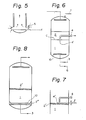
- Fig. 6 is a schematic diagram of an apparatus that is employed to perform these procedures.
- Backwashing water 3 is introduced into the resin-packed tank from below at a linear velocity (hereinafter abbreviated as LV) of 8 - 12 m/hr.
- LV linear velocity
- both SAR and SBR are allowed to settle and sluicing water 6 is introduced into the tank from below at an LV of 2.5 - 4 m/hr so as to fluidize the SBR layer 2.
- compressed air 7 is introduced from the top of the tank, thereby transferring SBR to the anion regeneration tank (not shown).
- SBR layer 2 but also SAR layer 1 is slightly fluidized by supplying the sluicing water 6.
- the open end 4 ⁇ of a resin transfer pipe 4 is disposed on the central axis of the tank.
- the open end 4 ⁇ may be disposed close to the wall of the tank or it may be in the form of a "trough".
- the pipe 4 is disposed in such a way that the open end 4 ⁇ is positioned slightly below the interface c between the two resin layers at the time when sluicing water 6 is introduced, and this is a commonly employed practice in commercial operations of condensate demineralization.
- the residual SBR consists of the following three portions: X : SBR 2 ⁇ situated on the surface layer of SAR and which is hatched in Fig. 8 (the same as SBR 2 ⁇ in Fig. 7); Y : SBR 2 ⁇ that is left in the neighborhood of the lower water collecting unit 10 and which is also hatched in Fig. 8; and Z : SBR left in the interior of the SAR layer.
- Portion Y of the residual SBR is unavoidably trapped in the neighborhood of the lower water collecting unit 10 when the mixed resin bed is transferred from a demineralizing tank (not shown) to the cation regenerating tank (which also serves as a separation tank), and residual SBR of this type occurs in a substantial amount irrespective of whether the lower water collecting unit is in the form of a perforated plate or a perforated pipe.
- This resin cannot be displaced or purged by the simple technique of backwashing and its volume sometimes amounts to as many as 1 - 3% of the total SBR.
- the method currently employed to purge the residual SBR 2 ⁇ is to supply backwashing water together with air that is simultaneously introduced into the lower water collecting unit in the same manner as air scrubbing is performed by conventional means.
- Portion Z of residual SBR can be removed by performing thorough backwashing after the problem with Y has been solved. Under ordinary conditions, the residual SBR in SAR is present in an amount of 0.05% or less. The SBR content can be further lowered by selecting an SAR/SBR combination that affords a great difference in both the specific gravity and the particle size distribution.
- sluicing water 6 is introduced through the intermediate sluicing pipe 11 in the upper layer of SAR 1 so as to attain a bed expansion ratio of 80 - 120% for SBR 2 by backwashing, with SBR 2 being selectively transferred through the resin pipe 4 in the lower layer of SBR 2.
- Japanese Utility Model Publication No. 17229/1985 discloses a system which, instead of a simple resin transfer pipe of the type shown in Fig. 6, employs a pipe with an opening that extends across the tank and which is positioned adjacent and in a face-to-face relationship with the header of a perforated intermediate sluicing pipe.
- Japanese Patent Publication Nos. 6339/1981 and 20312/1983, as well as British Patent No. 1,498,139 propose a process in which a plurality of spray nozzles that are disposed at the interface between two separated resin beds, or which are arranged in two rows, one above the interface and the other below said interface, produce horizontal water jets that separate one resin bed from the other and transfers it to a regeneration tank.
- this method also requires the use of complicated equipment and has yet to be commercialized.
- An object, therefore, of the present invention is to provide a method for transferring SBR as a separate entity from SAR, with the amount of residual SBR, in particular SBR 2 ⁇ remaining on the surface layer of SAR (i.e., residual SBR of type X), being minimized during transfer of SBR after it is separated in the resin separation tank.
- This method satisfies conditions (a) to (d) while enabling unattended operation in a fully automatic and highly reliable manner.
- the present invention provides a method for separating and transferring an ion-exchange resin from a tank packed with a mixed bed of two ion-exchange resins having different specific gravities, said method comprising:
- Fig. 1 shows the state of the separation tank after a mixed bed of resins received from a demineralizing tank (not shown) has been separated into two layers by backwashing and settled to form a stationary bed.
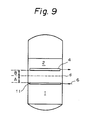
- a perforated separating/transferring intermediate sluicing pipe 11 is disposed below the interface d between two separated resin layers SAR and SBR, and a resin transfer pipe 4 is disposed in such a way that its open end 4 ⁇ is situated above the intermediate sluicing pipe 11.
- the distance (L1) between each of the lateral pipes 12 on the intermediate sluicing pipe 11 and the position f of the open end 4 ⁇ of the transfer pipe 4 is preferably set at 50 mm and above, more preferably at 80 mm and above.
- the distance (L2) between the interface d and the position f varies depending upon the amount of resin being transferred from the demineralizing tank.
- the process of the present invention can of course be performed successfully if the level of d is above that of f . Even if the level of d is below f , the process of the present invention can be performed satisfactorily if L2 is not more than about half the value of L1.
- the open end 4 ⁇ of the transfer pipe 4 is positioned on the central axis of the tank but it may be disposed in the neighborhood of the wall of the tank.
- the intermediate sluicing pipe 11 has four lateral pipes 12 but the number of lateral pipes to be employed may vary depending upon the diameter of the tank.
- the process of the present invention is performed in the separation tank equipped with the devices arranged in the manner described above. This process will proceed as follows.
- the mixed resin bed transferred from the demineralizing tank is backwashed and separated into two layers, with SAR 1 having the greater specific gravity being positioned below SBR 2 having the smaller specific gravity.
- SAR 1 having the greater specific gravity
- SBR 2 having the smaller specific gravity.
- sluicing water Q1 is introduced into the tank through the intermediate sluicing pipe 11 while pressurized water 8 is introduced from the top of the tank so as to transfer the greater part of SBR to an anion regeneration tank (not shown).
- the greater part of SBR is transferred to the anion regeneration tank and, at the same time, SAR situated above position f of the open end 4 ⁇ of the resin transfer pipe 4 is also transferred together with SBR.
- FIG. 8 A typical profile of the SBR that is left untransferred from the separation tank in the first step is shown in Fig. 8 and the residual SBR is composed of the following three portions: SBR 2 ⁇ lying over the SAR layer, SBR 2 ⁇ present in the neighborhood of the lower water collecting unit, and a small amount of SBR remaining in the interior of SAR layer 1 (the last-mentioned portion is not shown in Fig. 8).
- the portions of residual SBR that are present in large amounts are indicated as SBR 2 ⁇ and SBR 2 ⁇ .
- SBR 2 ⁇ and SBR which stays in a small amount in the interior of SAR layer 1 are purged by introducing air together with backwashing water as in the case of air scrubbing, thereby allowing these two portions of residual SBR to be collected on the SAR layer 1 together with SBR 2 ⁇ .
- backwashing is performed by introducing backwashing water 3 into the tank through the lower water collecting unit 10 at an LV of 6 - 12 m/hr which is commonly employed in the art.
- sluicing water Q2 is introduced through the intermediate sluicing pipe 11 at a faster flow rate than Q1, typically at an LV of 5 - 20 m/hr, preferably 10 - 16 m/hr.
- This second step is performed in order to ensure that SBR 2 ⁇ and the small amount of SBR, which have been dispersed in the SAR layer 1 as a result of the first step and the subsequent purging with the two-phase stream, are permitted to move to the surface layer of SAR 1 so that they can be collected as SBR 2 ⁇ .
- This purpose can be effectively attained by introducing backwashing water 3 together with sluicing water Q2 that is supplied through the intermediate sluicing pipe 11.
- a settling operation then follows.
- the settling operation is preferably carried out by continuing the supply of sluicing water Q2 while stopping the supply of backwashing water 3. It suffices that the SAR layer lying below the intermediate sluicing pipe 11 is allowed to settle in this step.
- sluicing water is introduced into the tank at a flow rate as high as the rate at which sluicing water Q2 is supplied in the second step.
- pressurized water 8 is introduced from above the tank so as to direct SBR 2 ⁇ to the open end 4 ⁇ of the resin transfer pipe 4 and transfer it through that pipe.
- Sluicing water Q2 is jetted through lateral pipes 12 on the intermediate sluicing pipe 11 so as to lift the particles of residual SBR 2 ⁇ in water in the freeboard above the resin layer and to transfer SBR 2 ⁇ through the pipe 4.
- the particles of lifted SBR 2 ⁇ are sucked into the open end 4 ⁇ of the pipe 4 under the pressure of water 8 being supplied at an LV of 4 - 5 m/hr, as indicated by arrows in Fig. 4, and are smoothly transferred through the pipe 4.
- the SAR above the lateral pipes 12 is fluidized depending upon the flow rate of sluicing water Q2 and part of the particles in the resin bed expanded by backwashing are lifted and transferred together with SBR 2 ⁇ .
- the distance l ⁇ between the open end 4 ⁇ of the pipe 4 and the surface layer of SAR that lies above the lateral pipes 12 and which is being expanded in volume by backwashing increases, thereby decreasing the amount of SAR whose particles are lifted and transferred but increasing the proportion of SBR 2 ⁇ whose particles are lifted and transferred.
- substantially all part of SBR 2 ⁇ is transferred from the separation tank through the pipe 4.
- the present inventors discovered this phenomenon in an experiment on a large-scale separation tank and found that it was advantageous for the purpose of selectively transferring the residual SBR 2 ⁇ .
- FIG. 2 An example of the intermediate sluicing pipe 11 that may be employed in the present invention is shown in Figs. 2 and 3.
- each of the lateral pipes 12 on the intermediate sluicing pipe 11 is provided with orifices 13 at given pitches and is entirely covered with a net 14.
- Fig. 3 is an end view of the lateral pipe, which shows that an orifice 13 is also provided at both ends of the lateral pipe
- Net 14 may be of any design that permits the passage of water but not ion-exchange resins, and a suitable example is a synthetic fiber filter cloth (e.g. Saran® net), a wire net or a wedge wire net.
- a synthetic fiber filter cloth e.g. Saran® net
- wire net e.g. a wire net or a wedge wire net.
- the present inventors found that when, under the conditions (1) and (2), sluicing water Q2 was introduced at an LV of at least 5 m/hr, preferably at least 10 m/hr, the water jetted from the lateral pipes 12 through horizontal orifices 13 impinged against the net 14 and spread suffi strictlyciently, in particular, in horizontal and upward directions, to cause the particles of less heavy SBR to be lifted as shown in Fig. 4.
- V1 is preferably set at 8 m/sec and below. Specifically, it is preferred that sluicing water Q2 is supplied at an LV of 10 m/hr and above while orifices 13 are designed to ensure V1 of at least 4 m/sec.
- the position f of the open end 4 ⁇ of the resin transfer pipe 4 is then selected so that it matches e .
- L1 or the distance between e and f is typically set at 50 mm or greater, preferably 80 mm or greater, in the embodiment shown in Fig. 1. If L1 is small, the distance (l ⁇ ) between the level e of the top of lateral pipe 12 and the position h of the surface layer of SAR being expanded in volume by backwashing with sluicing water Q2 is also decreased and it becomes impossible to ensure effective lifting of the particles of SBR 2 ⁇ .
- the effective value of L1 was preferably at least 80 mm, more preferably between 100 and 180 mm. If L1 is excessive, l ⁇ also becomes excessive, which is unfavorable for the purpose of effectively lifting the particles of SBR 2 ⁇ .
- the open end 4 ⁇ of the resin transfer pipe 4 may have a simple shape as shown in Fig. 5.
- the arrows in Fig. 5 indicate the direction of a resin stream.
- the open end 4 ⁇ of the transfer pipe 4 may be of such a shape that SBR 2 ⁇ is sucked in horizontally, not from beneath the open end 4 ⁇ .
- the total area of the cutout 5 through which the resin is sucked into the open end 4 ⁇ may be such that it permits the passage of sluicing water Q2 and pressurized water 8 at a total LV of not faster than 7,000 m/hr.
- the position f of open end 4 ⁇ is flush with the bottom end of the cutout 5.
- the height of SAR 1 is typically on the order of 1,500 mm and the variation in the level of SAR 1 after the transfer of SBR 2 ⁇ is as small as 1%.
- the process of the present invention fully satisfies the requirement that the level of SAR 1 should remain fairly constant after the transfer of SBR 2 ⁇ .
- the present inventors conducted an experiment in which a mixed resin bed received from a demineralizing tank was separated into two layers by backwashing and subjected to a settling treatment for producing a stationary bed.
- SBR 2 ⁇ could be transported smoothly even when the position d (see Fig. 1) of the interface between separated layers fluctuated considerably.
- the process of the present invention has the additional advantage of simplicity in equipment design as is clear from Figs. 1 and 4. Furthermore, the resin separation and transfer can be performed with the conventionally employed concentration of resin slurry that does not involve any potential of resin wear.
- part of SAR is also transferred to an anion regeneration tank together with SBR 2.
- the so transferred SAR will become a resin of R-Na form upon contact with NaOH used as a regenerant for SBR.
- the formation of the R-Na form resin may be prevented by a conventional method such as the one disclosed in Japanese Patent No. 1027750.
- process II an additional cycle of the second and third steps is performed following process I.
- the flow rate of sluicing water supplied in the first cycle of second and third steps is decreased as compared with the case of process I, thereby enabling a higher flow rate of sluicing water to be supplied in the second cycle of second and third steps.
- a schedule of the supply of sluicing water in each of the processes I and II is shown in Table 1.
- the present inventors confirmed by experimentation that when the first cycle of the second and third steps was performed with sluicing water Q2 being supplied at a LV of 6 - 10 m/hr, a smaller amount of residual SBR 2 ⁇ (hatched in Fig. 4) formed in the tank than what remained after the first step was performed in process I, thereby achieving a significant decrease in the finally remaining SBR 2 ⁇ as compared with process I when the procedures of SBR transfer had been completed.
- Valves 16 and 17 are opened and backwashing water is supplied at a rate of 8 - 12 m/hr to separate the mixed resin bed into two layers. Valves 16 and 17 are then closed and resin SAR is allowed to settle. Valves 23 and 18 are opened and pressurized water 8 and sluicing water Q1 are supplied at low rates (LV) of 4 - 5 m/hr and 2 - 4 m/hr, respectively, so as to transfer the greater part of SBR to an anion regeneration tank (not shown) with valve 9 being opened.
- LV low rates
- Step of purging SBR 2 ⁇ from the neighborhood of the lower water collecting unit 10 Step of purging SBR 2 ⁇ from the neighborhood of the lower water collecting unit 10 :
- LV 8 - 12 m/hr
- Valve 21 is closed and backwashing is performed by supplying backwashing water 3 with valves 16 and 17 being left open. Two to three minutes later, valve 19 is opened and sluicing water Q2 is supplied at LV of 10 - 16 m/hr. Sluicing water Q2 may be introduced simultaneously with backwashing water 3. As a result, a linear velocity of 8 - 12 m/hr is provided by backwashing water 3 below the intermediate sluicing pipe 11 while LV of at least 20 m/hr is created above the pipe 11 by the combination of backwashing water 3 and sluicing water Q2.
- SBR 2 ⁇ purged in the previous step is carried to the surface layer of SAR 1 and collected as SBR 2 ⁇ . The purpose of the second step is satisfactorily attained by performing it for 5 - 6 minutes.
- a settling treatment is performed. This may be done with all valves closed; alternatively, sluicing water Q2 may be continuously supplied with valves 19 and 17 left open. All that is required to accomplish in this step is to form a stationary SAR bed below the lateral pipes 12 on the intermediate sluicing pipe 11.
- valves 19 and 23 are opened and sluicing water Q2 and pressurized water 8 are introduced at flow rates (LV) of 10 - 16 m/hr and 4 - 5 m/hr, so that the particles of residual SBR 2 ⁇ are lifted in the water in the freeboard and transferred from the tank with valve 9 being opened.
- This step is typically performed for a period of 5 - 10 minutes.
- Process II may be performed in the following manner.
- Step of purging SBR 2 ⁇ from the neighborhood of the lower water collecting unit 10 Step of purging SBR 2 ⁇ from the neighborhood of the lower water collecting unit 10 :
- Second step (in first cycle) Second step (in first cycle):
- Second step (in second cycle) Second step (in second cycle):
- a separation tank having an inside diameter of 1,800 mm and a height of 5,000 mm was packed with a mixture of 4,500 l of Dowex® TG 650C (serving as SAR) and 2,000 l of Dowex® TG 550A (SBR).
- a resin transfer pipe was installed in the tank in such a way that its open end would be positioned on the central axis of the tank and 150 mm below the interface between separate layers of SAR and SBR.
- the amount of residual SBR was measured by the following procedures: after SBR transfer was completed, the tank was drained of water; uniform sampling was conducted for each resin layer in the direction of its depth; and the amount of residual SBR was determined by gravitational separation with NaOH.
- a separation tank of the same type as used in Comparative Examples 1 and 2 was employed except that the separating transfer pipe 11 was modified as noted below. This tank was packed with the same resins as those employed in Comparative Examples 1 and 2. Resin transfer was performed in accordance with process I.
- backwashing water was supplied at LV of 10 m/hr to perform backwashing for 10 minutes so as to separate the mixed resin bed into two layers.
- Step of purging SBR 2 ⁇ from the neighborhood of the lower water collecting unit Step of purging SBR 2 ⁇ from the neighborhood of the lower water collecting unit :
- the water level was lowered to 300 mm below the surface resin layer. Thereafter, backwashing water and air were supplied to the lower water collecting unit for 4 minutes at respective flow rates (LV) of 10 m/hr and 100 m/hr.
- LV flow rates
- backwashing water was supplied to the lower water collecting unit at LV of 10 m/hr so as to perform backwashing for 2 minutes.
- Sluicing water was then supplied through the intermediate sluicing pipe for 5 minutes at LV of 14 m/hr.
- Example 2 The procedures of Example 1 were repeated except that the distance (L1) between e and f was changed to 180, 80, 50 and 30 mm. The results are shown in Table 2.
- backwashing water was supplied at LV of 10 m/hr so as to perform backwashing for 10 minutes until the mixed resin bed separated into two layers.
- Sluicing water (Q1) was supplied at LV of 2.5 m/hr. Pressurized water was supplied from the top of the tank at LV of 4 m/hr. This step was performed for 20 minutes.
- Step of purging SBR 2 ⁇ from the neighborhood of the lower water collecting unit Step of purging SBR 2 ⁇ from the neighborhood of the lower water collecting unit :
- the water level was lowered to 300 mm below the surface resin layer.
- Backwashing water and air were supplied to the lower water collecting unit for 4 minutes at respective rates (LV) of 10 m/hr and 100 m/hr.
- backwashing water was supplied to the lower water collecting unit at LV of 10 m/hr to perform backwashing for 2 minutes.
- Sluicing water was then supplied through the intermediate sluicing pipe for 5 minutes at LV of 8 m/hr.
- backwashing water was supplied to the lower water collecting unit at LV of 10 m/hr to perform backwashing for 2 minutes.
- Sluicing water was then supplied through the intermediate sluicing pipe for 3 minutes at LV of 14 m/hr.
- Example 4 The procedures of Example 4 were repeated except that the flow rate of sluicing water supplied through the intermediate sluicing pipe in the second and third steps in the second cycle was changed to LV of 10, 12 and 16 m/hr. The results are shown in Table 2.
- the present invention provides a reliable process for reducing the amount of a residual anion resin (SBR) in a cation regeneration tank to 0.1% and below (Examples 4 and 5). Therefore, the formation of R-Cl or R-SO4 in significantly reduced as compared with the result of the prior art.
- SBR residual anion resin
- the process of the present invention enables efficient separation and transfer of SBR in a fully automatic and unattended way in spite of variations in the resin level (as in Example 3) or in the supply rate of sluicing water (as in Example 5).
- This process solves all of the problems associated with the prior art and is anticipated to make great contribution to industries at large.
Landscapes
- Chemical & Material Sciences (AREA)
- Organic Chemistry (AREA)
- Chemical Kinetics & Catalysis (AREA)
- Treatment Of Water By Ion Exchange (AREA)
Applications Claiming Priority (4)
| Application Number | Priority Date | Filing Date | Title |
|---|---|---|---|
| JP30776386 | 1986-12-25 | ||
| JP307763/86 | 1986-12-25 | ||
| JP62061384A JPH0659412B2 (ja) | 1986-12-25 | 1987-03-18 | イオン交換樹脂の分離移送方法 |
| JP61384/87 | 1987-03-18 |
Publications (3)
| Publication Number | Publication Date |
|---|---|
| EP0273339A2 true EP0273339A2 (de) | 1988-07-06 |
| EP0273339A3 EP0273339A3 (en) | 1988-11-17 |
| EP0273339B1 EP0273339B1 (de) | 1992-06-24 |
Family
ID=26402427
Family Applications (1)
| Application Number | Title | Priority Date | Filing Date |
|---|---|---|---|
| EP87118916A Expired - Lifetime EP0273339B1 (de) | 1986-12-25 | 1987-12-21 | Methode zum Scheiden und Überführen eines Ionenaustauscherharzes |
Country Status (4)
| Country | Link |
|---|---|
| US (1) | US4891138A (de) |
| EP (1) | EP0273339B1 (de) |
| JP (1) | JPH0659412B2 (de) |
| DE (1) | DE3780018T2 (de) |
Cited By (2)
| Publication number | Priority date | Publication date | Assignee | Title |
|---|---|---|---|---|
| CN107293343A (zh) * | 2017-06-12 | 2017-10-24 | 航天晨光股份有限公司 | 核电站废树脂的装载卸载转运装置及其转运方法 |
| CN114620808A (zh) * | 2022-04-12 | 2022-06-14 | 宁夏厚德环保科技有限公司 | 一种离子交换水处理装置 |
Families Citing this family (9)
| Publication number | Priority date | Publication date | Assignee | Title |
|---|---|---|---|---|
| US5066375A (en) * | 1990-03-19 | 1991-11-19 | Ionics, Incorporated | Introducing and removing ion-exchange and other particulates from an assembled electrodeionization stack |
| US5736052A (en) * | 1995-11-27 | 1998-04-07 | Framatome Technologies, Inc. | Ion exchange resin particle separation system |
| ITMI20020106A1 (it) * | 2002-01-22 | 2003-07-22 | Tm E S P A Termomeccanica Ecol | Impianto a resine a scambio ionico |
| JP2009106882A (ja) * | 2007-10-31 | 2009-05-21 | Noritz Corp | 軟水器 |
| CN101816960B (zh) * | 2010-04-06 | 2012-07-04 | 海盐力源电力设备有限公司 | 前置阳床阳离子再生塔 |
| WO2012048116A2 (en) * | 2010-10-06 | 2012-04-12 | Electric Power Research Institute Inc. | Ion exchange regeneration and nuclide specific selective processes |
| US9005448B2 (en) | 2011-08-12 | 2015-04-14 | General Electric Company | Mobile water treatment and resin transfer hub |
| JP6315611B2 (ja) * | 2015-11-30 | 2018-04-25 | 壽化工機株式会社 | 混床式樹脂充填塔の混合樹脂の分離方法、混床式樹脂充填塔、及び水処理装置 |
| JP7124397B2 (ja) * | 2018-04-09 | 2022-08-24 | 栗田工業株式会社 | カチオン交換樹脂再生塔 |
Family Cites Families (21)
| Publication number | Priority date | Publication date | Assignee | Title |
|---|---|---|---|---|
| US3583908A (en) * | 1968-09-25 | 1971-06-08 | Crane Co | Condensate purification process |
| US3719591A (en) * | 1971-03-05 | 1973-03-06 | Crane Co | Method for condensate filtration and demineralization |
| GB1498139A (en) * | 1976-03-19 | 1978-01-18 | Clarke Chapman Ltd | Ion exchange method and apparatus |
| US4038855A (en) * | 1976-04-19 | 1977-08-02 | Aetna-Standard Engineering Company | Stretch reducing mill |
| JPS546339A (en) * | 1977-06-15 | 1979-01-18 | Nichi Bei Blind Mfg | Elevator for blades of venetian blind |
| JPS5420312A (en) * | 1977-07-15 | 1979-02-15 | Hitachi Ltd | Rotor of magnet generator |
| JPS5514718A (en) * | 1978-07-17 | 1980-02-01 | Seiko Epson Corp | Mos transistor circuit |
| JPS5520636A (en) * | 1978-08-01 | 1980-02-14 | Japan Organo Co Ltd | Regenerating method of mixed ion exchange resin of condensation desalting apparatus |
| JPS5588860A (en) * | 1978-12-28 | 1980-07-04 | Japan Organo Co Ltd | Taking-out method for ion exchange resin |
| JPS5815016A (ja) * | 1981-07-15 | 1983-01-28 | Mitsubishi Mining & Cement Co Ltd | 動物の骨からリン酸カルシウム化合物を製造する方法 |
| JPS5827982A (ja) * | 1981-08-12 | 1983-02-18 | Hitachi Ltd | エツチング装置 |
| JPS5886454A (ja) * | 1981-11-19 | 1983-05-24 | Ebara Corp | 処理塔内監視装置 |
| JPS595015A (ja) * | 1982-07-02 | 1984-01-11 | Hitachi Ltd | モ−ルド型構造 |
| JPS5935260A (ja) * | 1982-08-24 | 1984-02-25 | Nec Corp | デ−タ圧縮書込み装置 |
| JPS60122045A (ja) * | 1983-12-07 | 1985-06-29 | Ebara Corp | イオン交換樹脂の分離方法 |
| JPS60132653A (ja) * | 1983-12-20 | 1985-07-15 | Japan Organo Co Ltd | イオン交換樹脂の移送方法 |
| JPH0617229A (ja) * | 1992-07-02 | 1994-01-25 | Mitsubishi Materials Corp | 表面被覆サーメット製切削工具 |
| JP2906839B2 (ja) * | 1992-07-15 | 1999-06-21 | 日本電気株式会社 | 電子走査型2次監視レーダー装置 |
| JP3268016B2 (ja) * | 1992-08-04 | 2002-03-25 | 中部電力株式会社 | 水力機械 |
| JP3234644B2 (ja) * | 1992-08-10 | 2001-12-04 | 川崎製鉄株式会社 | 耐二次加工脆性に優れる高r値高張力冷延鋼板及びその製造方法 |
| JPH06132054A (ja) * | 1992-10-16 | 1994-05-13 | Fuji Xerox Co Ltd | ケーブル用コネクタ |
-
1987
- 1987-03-18 JP JP62061384A patent/JPH0659412B2/ja not_active Expired - Lifetime
- 1987-12-21 EP EP87118916A patent/EP0273339B1/de not_active Expired - Lifetime
- 1987-12-21 DE DE8787118916T patent/DE3780018T2/de not_active Expired - Fee Related
- 1987-12-24 US US07/137,714 patent/US4891138A/en not_active Expired - Lifetime
Cited By (3)
| Publication number | Priority date | Publication date | Assignee | Title |
|---|---|---|---|---|
| CN107293343A (zh) * | 2017-06-12 | 2017-10-24 | 航天晨光股份有限公司 | 核电站废树脂的装载卸载转运装置及其转运方法 |
| CN107293343B (zh) * | 2017-06-12 | 2019-04-12 | 航天晨光股份有限公司 | 核电站废树脂的装载卸载转运装置及其转运方法 |
| CN114620808A (zh) * | 2022-04-12 | 2022-06-14 | 宁夏厚德环保科技有限公司 | 一种离子交换水处理装置 |
Also Published As
| Publication number | Publication date |
|---|---|
| JPH0659412B2 (ja) | 1994-08-10 |
| JPS63258649A (ja) | 1988-10-26 |
| US4891138A (en) | 1990-01-02 |
| DE3780018T2 (de) | 1993-01-14 |
| EP0273339A3 (en) | 1988-11-17 |
| DE3780018D1 (de) | 1992-07-30 |
| EP0273339B1 (de) | 1992-06-24 |
Similar Documents
| Publication | Publication Date | Title |
|---|---|---|
| US4648976A (en) | Integral water demineralizer system and method | |
| EP0273339A2 (de) | Methode zum Scheiden und Überführen eines Ionenaustauscherharzes | |
| US3382169A (en) | Process for deionizing aqueous solutions | |
| US4457841A (en) | Regeneration of ion exchange materials | |
| EP0004792B1 (de) | Verfahren zum Ionenaustausch mit beweglichem Fliessbett | |
| US2891007A (en) | Method of regenerating ion exchangers | |
| US4913803A (en) | Particle separation system | |
| US3674685A (en) | Process of and apparatus for the ion-exchange treatment of liquids | |
| US3775310A (en) | Continuous ion exchange | |
| CA1183973A (en) | Regeneration of ion exchange materials | |
| US4663051A (en) | Regeneration of mixed bed demineralizers | |
| EP0594334B1 (de) | Methode zum Regenerieren von Harzen zur Verwendung in der Wasserreinigung | |
| JPH0478344B2 (de) | ||
| US5269936A (en) | Process for treating ion exchange resin | |
| US4622141A (en) | Method and apparatus for withdrawing a layer of material from a vessel | |
| US3595394A (en) | Water-demineralizing apparatus with a central regenerant collecting and distributing device | |
| US5212205A (en) | Regeneration of deep bed condensate polishers | |
| JPS5940063B2 (ja) | イオン交換樹脂の洗浄法及びその装置 | |
| US5196122A (en) | External regeneration system for mixed bed ion exchangers | |
| JPH0677687B2 (ja) | イオン交換樹脂の再生方法 | |
| CN111116547B (zh) | 劣质环丁砜再生设备、系统和方法 | |
| CA2027275C (en) | Process and apparatus for treating ion exchange resin | |
| JPH0661466B2 (ja) | イオン交換樹脂の分離移送方法 | |
| JPH0511495B2 (de) | ||
| GB2027610A (en) | Regeneration of Ion Exchange Materials |
Legal Events
| Date | Code | Title | Description |
|---|---|---|---|
| PUAI | Public reference made under article 153(3) epc to a published international application that has entered the european phase |
Free format text: ORIGINAL CODE: 0009012 |
|
| AK | Designated contracting states |
Kind code of ref document: A2 Designated state(s): DE FR GB |
|
| PUAL | Search report despatched |
Free format text: ORIGINAL CODE: 0009013 |
|
| AK | Designated contracting states |
Kind code of ref document: A3 Designated state(s): DE FR GB |
|
| 17P | Request for examination filed |
Effective date: 19890516 |
|
| 17Q | First examination report despatched |
Effective date: 19900206 |
|
| GRAA | (expected) grant |
Free format text: ORIGINAL CODE: 0009210 |
|
| AK | Designated contracting states |
Kind code of ref document: B1 Designated state(s): DE FR GB |
|
| REF | Corresponds to: |
Ref document number: 3780018 Country of ref document: DE Date of ref document: 19920730 |
|
| ET | Fr: translation filed | ||
| PLBE | No opposition filed within time limit |
Free format text: ORIGINAL CODE: 0009261 |
|
| STAA | Information on the status of an ep patent application or granted ep patent |
Free format text: STATUS: NO OPPOSITION FILED WITHIN TIME LIMIT |
|
| 26N | No opposition filed | ||
| PGFP | Annual fee paid to national office [announced via postgrant information from national office to epo] |
Ref country code: FR Payment date: 20011119 Year of fee payment: 15 |
|
| PGFP | Annual fee paid to national office [announced via postgrant information from national office to epo] |
Ref country code: GB Payment date: 20011211 Year of fee payment: 15 |
|
| PGFP | Annual fee paid to national office [announced via postgrant information from national office to epo] |
Ref country code: DE Payment date: 20011221 Year of fee payment: 15 |
|
| REG | Reference to a national code |
Ref country code: GB Ref legal event code: IF02 |
|
| PG25 | Lapsed in a contracting state [announced via postgrant information from national office to epo] |
Ref country code: GB Free format text: LAPSE BECAUSE OF NON-PAYMENT OF DUE FEES Effective date: 20021221 |
|
| PG25 | Lapsed in a contracting state [announced via postgrant information from national office to epo] |
Ref country code: DE Free format text: LAPSE BECAUSE OF NON-PAYMENT OF DUE FEES Effective date: 20030701 |
|
| GBPC | Gb: european patent ceased through non-payment of renewal fee |
Effective date: 20021221 |
|
| PG25 | Lapsed in a contracting state [announced via postgrant information from national office to epo] |
Ref country code: FR Free format text: LAPSE BECAUSE OF NON-PAYMENT OF DUE FEES Effective date: 20030901 |
|
| REG | Reference to a national code |
Ref country code: FR Ref legal event code: ST |