EP0273362A1 - Tintenstrahlaufzeichnungsgerät - Google Patents
Tintenstrahlaufzeichnungsgerät Download PDFInfo
- Publication number
- EP0273362A1 EP0273362A1 EP87119043A EP87119043A EP0273362A1 EP 0273362 A1 EP0273362 A1 EP 0273362A1 EP 87119043 A EP87119043 A EP 87119043A EP 87119043 A EP87119043 A EP 87119043A EP 0273362 A1 EP0273362 A1 EP 0273362A1
- Authority
- EP
- European Patent Office
- Prior art keywords
- cap
- valve
- ink
- jet recording
- ink jet
- Prior art date
- Legal status (The legal status is an assumption and is not a legal conclusion. Google has not performed a legal analysis and makes no representation as to the accuracy of the status listed.)
- Granted
Links
Images




Classifications
-
- B—PERFORMING OPERATIONS; TRANSPORTING
- B41—PRINTING; LINING MACHINES; TYPEWRITERS; STAMPS
- B41J—TYPEWRITERS; SELECTIVE PRINTING MECHANISMS, i.e. MECHANISMS PRINTING OTHERWISE THAN FROM A FORME; CORRECTION OF TYPOGRAPHICAL ERRORS
- B41J2/00—Typewriters or selective printing mechanisms characterised by the printing or marking process for which they are designed
- B41J2/005—Typewriters or selective printing mechanisms characterised by the printing or marking process for which they are designed characterised by bringing liquid or particles selectively into contact with a printing material
- B41J2/01—Ink jet
- B41J2/135—Nozzles
- B41J2/165—Prevention or detection of nozzle clogging, e.g. cleaning, capping or moistening for nozzles
- B41J2/16517—Cleaning of print head nozzles
- B41J2/1652—Cleaning of print head nozzles by driving a fluid through the nozzles to the outside thereof, e.g. by applying pressure to the inside or vacuum at the outside of the print head
- B41J2/16523—Waste ink transport from caps or spittoons, e.g. by suction
-
- B—PERFORMING OPERATIONS; TRANSPORTING
- B41—PRINTING; LINING MACHINES; TYPEWRITERS; STAMPS
- B41J—TYPEWRITERS; SELECTIVE PRINTING MECHANISMS, i.e. MECHANISMS PRINTING OTHERWISE THAN FROM A FORME; CORRECTION OF TYPOGRAPHICAL ERRORS
- B41J2/00—Typewriters or selective printing mechanisms characterised by the printing or marking process for which they are designed
- B41J2/005—Typewriters or selective printing mechanisms characterised by the printing or marking process for which they are designed characterised by bringing liquid or particles selectively into contact with a printing material
- B41J2/01—Ink jet
- B41J2/135—Nozzles
- B41J2/165—Prevention or detection of nozzle clogging, e.g. cleaning, capping or moistening for nozzles
- B41J2/16505—Caps, spittoons or covers for cleaning or preventing drying out
- B41J2/16508—Caps, spittoons or covers for cleaning or preventing drying out connected with the printer frame
-
- B—PERFORMING OPERATIONS; TRANSPORTING
- B41—PRINTING; LINING MACHINES; TYPEWRITERS; STAMPS
- B41J—TYPEWRITERS; SELECTIVE PRINTING MECHANISMS, i.e. MECHANISMS PRINTING OTHERWISE THAN FROM A FORME; CORRECTION OF TYPOGRAPHICAL ERRORS
- B41J2/00—Typewriters or selective printing mechanisms characterised by the printing or marking process for which they are designed
- B41J2/005—Typewriters or selective printing mechanisms characterised by the printing or marking process for which they are designed characterised by bringing liquid or particles selectively into contact with a printing material
- B41J2/01—Ink jet
- B41J2/17—Ink jet characterised by ink handling
- B41J2/19—Ink jet characterised by ink handling for removing air bubbles
-
- B—PERFORMING OPERATIONS; TRANSPORTING
- B41—PRINTING; LINING MACHINES; TYPEWRITERS; STAMPS
- B41J—TYPEWRITERS; SELECTIVE PRINTING MECHANISMS, i.e. MECHANISMS PRINTING OTHERWISE THAN FROM A FORME; CORRECTION OF TYPOGRAPHICAL ERRORS
- B41J2/00—Typewriters or selective printing mechanisms characterised by the printing or marking process for which they are designed
- B41J2/005—Typewriters or selective printing mechanisms characterised by the printing or marking process for which they are designed characterised by bringing liquid or particles selectively into contact with a printing material
- B41J2/01—Ink jet
- B41J2/17—Ink jet characterised by ink handling
- B41J2/20—Ink jet characterised by ink handling for preventing or detecting contamination of compounds
Definitions
- This invention relates to an ink jet recording apparatus.
- An apparatus of this type has a discharge port of a minute diameter usually of the order of ⁇ 30 - 100 ⁇ m for discharging recording liquid droplets.
- the apparatus of this type is left unused under the room temperature or high temperatures for a long period of time, the water content in the recording liquid (ink) is vaporized and the viscosity of the ink near the discharge port is readily increased or the adherence of the ink occurs and thus, formation of recording liquid droplets becomes impossible in some cases.
- some of apparatuses according to the prior art are provided with a cap for capping the discharge port during the non-operation of the apparatuses to thereby prevent the vaporization of ink from the discharge port, or are provided with a mechanism for forcibly sucking ink from the discharge port during the non-discharge of recording liquid droplets.
- An object of the invention is to provide an ink jet recording apparatus comprising a discharge port for discharging the ink, a storing portion for storing the ink therein, a cap for covering said discharging port, pump means communicated with said cap, a sucking tube for communicating said cap with said storing portion and a valve provided in said sucking tube.
- Another object of the invention is to provide an ink jet recording apparatus comprising an ink jet recording head having a discharge port for discharging the ink, a cap abutting said head to cover said discharge port, abutting means for abutting said head with said cap, storing portion for storing the ink therein supplied to said head, a sucking tube for communicating said cap with said storing portion, pump means for generating sucking force for communicating said cap, a valve provided in said sucking tube; and control means for controlling said abutting means, said pump means and said valve.
- Further object of the invention is to provide a method for recovering the suction comprising (a) capping with a cap a discharge port of an ink jet recording head, (b) driving a pump to such in the cap in said capping state, ink and/or gas being sucked from a storing portion for storing the ink which is supplied to said discharge port and/or said head, (c) releasing said capping after said driving is stopped; and (d) closing a valve provided in the connected path between said cap and said storing portion after releasing said capping.
- Still further object of the invention is to provide a method for recovering the suction comprising (a) capping with a cap a discharge port of an ink jet recording head, said capping being performed in the condition that a valve communicates said cap with the open air, said valve being provided in a connecting path communicating said cap with a storing portion storing the ink supplied to said head, (b) operating said valve so as to communicate said cap with said storing portion in said capping state, (c) driving a pump so as to suck in said cap after said valve is operated; and (d) releasing said capping after said driving is stopped.
- each element is designed such that in the discharge restoring operation, ink is introduced from a storing member into a joining member and the vicinity of a discharge port is washed, whereby even when there is present viscosity-increased or adhering ink in the discharge port, such ink can be reliably removed.
- Figures 1 and 2 illustrate a first embodiment of the present invention, and in Figure 1, there is shown a schematic perspective view of an ink jet recording apparatus to which the present invention is applied.
- the reference numeral 1 designates a head unit having an ink jet recording head according to the present embodiment and a sub-tank for temporarily storing ink therein. Design has been made such that liquid such as ink supplied from a main tank 2 through a supply tube 3 is discharged from the recording head 1 and forms flying liquid droplets to thereby accomplish recording on a recording sheet 4 such as paper.
- the reference numeral 5 denotes a discharge restoring pump used when unsatisfactory discharge or non-discharge of liquid droplets occurs.
- This pump 5 generates a suction force for sucking the liquid from an ink suction port disposed in a cap 9 joinable through a suction tube 6 so as to cover a discharge port provided in the head of the head unit and communicating with the sub-tank and for restoring the discharging operation.
- the sucked ink has been directed into a waste liquid reservoir 8 and stored therein.
- the cap 9 has been disposed, for example, at the home position outside the recording area so as to be capable of opposing the head unit 1, and has also been used to prevent the ink in the head unit 1 from drying or foreign materials such as dust and the like from mixing with the ink when ink jet recording is not effected for a long period of time or when the apparatus is being transported.
- the cap 9 has been designed so as to move; in the direction of arrow C and join with the discharge port located at the fore end of the head unit 1 so as to cover the discharge port.
- the reference numeral 10 designates a carriage carrying the head unit 1 thereon and scanned in the direction of arrow S
- the reference numeral 11 denotes a platen for conveying the recording sheet 4 in the direction of arrow f while controlling the recording surface by the head unit 1.
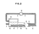
- Figure 2 is a schematic cross-sectional view illustrating the positional relations between various elements in the ink jet recording apparatus shown in Figure 1 when the head unit including an ink jet recording head is positioned at the home position opposed to the cap 9.
- the reference numeral 14 designates a discharge port formed at the end of an ink liquid path 17.
- the ink 16 supplied through the ink liquid path 17 has been discharged from the discharge port 14 and flown as liquid droplets.
- the reference numeral 18 denotes a cylindrical piezo-electric element which is one of discharge energy generating members for generating energy used to discharge the liquid.
- the cylindrical piezo-electric element has been mounted along the ink liquid path 17 so as to surround the ink liquid path 17.
- the reference numeral 15 designates a sub-tank which is an example of storing portion for temporarily storing therein the ink supplied by the ink tank 2.
- suction has been effected by the pump 5 shown in Figure 1 through a suction tube 7, whereby the liquid surface in the sub-tank 15 has been kept at a predetermined position.
- the suction tube 7 communicates the sub-tank 15 with an ink sucking port 13 disposed in the cap 9, and a valve 12 is provided half-way of the suction tube 7.
- FIG. 3 shows an example of the construction of the control system of the apparatus according to the present embodiment.
- the reference numeral 200 designates a control unit, for example, in the form of a microcomputer having CPU, ROM, RAM, etc.
- the control unit 200 has been designed to control various parts in accordance with the processing procedure shown in Figure 4 which is stored in the ROM, and drive the piezo-electric element 18 of the head unit 1 with respect to image data received from a host apparatus or the like to thereby accomplish recording.
- PS denotes a sheet sensor for detecting a recording sheet P.
- the control unit 200 has driven the platen roller 11 through a sheet feeding mechanism 11A including a sheet feeding motor and controlled the sheet feeding.
- CS designates a carriage position sensor. In conformity with positional information detected by the carriage position sensor CS, the control unit 200 has controlled the driving of the carriage 10 and the positioning to the home position, etc. through a carriage motor 10A.
- Designated by 9A is a conveying mechanism (abutting means) having a transmission mechanism such as gears and a cam and a driving member such as a motor for conveying the cap 9 in the direction of arrow C in Figure 1.
- the reference numerals 1205 and 1255 denote command means and indicating means, respectively, provided on an operating panel, not shown.
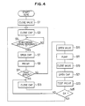
- Shown in Figure 4 is an example of the recording operation procedure according to the present embodiment.
- the valve 12 When the main switch has first been closed, the present procedure has been started, and at step S1, the valve 12 has been closed, and at step S3, the head unit 1 has been positioned at the home position and capping has been done by moving the cap 9 with the abutting means, and at step S5, the standby state has been brought about. That is, in the standby state, capping has been done and the discharge port 14 has been hermetically sealed, whereby vaporization of the water content in the ink has been prevented. Thereby, the unsatisfactory discharge due to the increase in viscosity and the adherence of the ink in and near the discharge port could be prevented. At that time, the valve 12 has been effective even if it has been opened.
- step S11 the recording condition has been judged and if the condition is good, shift has been made via step S3 to the standby state of step S5.
- This judgment of the recording condition could be done by visual watch or by an unsatisfactory record detecting device disposed specially. When unsatisfactory recording has occurred, the restoring operation of step S13 and subsequent steps has been performed.
- step S13 the head unit 1 has been positioned at the home position and capping has been done by the cap 9, whereafter at step S15, the valve 12 has been opened.
- step S17 the pump 5 has been driven to effect suction, the ink 16 has been sucked from the discharge port 14 and, since the valve 12 is open, the air and ink have been sucked from the ink sucking port 13 and the ink surface in the sub-tank 15 has been kept at a predetermined level.
- This driving of the pump 5 might be automatically effected by the command from the control unit 200 as shown in Figure 3, or might be manually effected.
- test recording has been effected at steps S19 - S25. That is, at step S19, the valve 12 has been again closed, and at step S21, the valve 12 has been opened, and at steps S23 and S25, the recording condition has been judged.
- step S13 where the restoring operation by the pump 5 has been again performed
- step S3 where the head unit 1 has been positioned at the home position and the cap 9 has been closed to bring about the standby state.
- the test print of step S19 and subsequent steps may or may not be effected, but it is preferable in that reliable unsatisfactory discharge is confirmed to effect test print.
- FIGS 5 and 6 show another embodiment of the present invention.
- portions which can be constructed similarly to the portions of the embodiment shown in Figures 1 and 2 are given similar reference numerals.
- a three-way valve 10 is disposed instead of the valve 12, half-way of the suction tube 7.
- Designated by the reference numeral 20 is an open air communicating hole formed in the tree-way valve 19.
- the three-way valve 19 serves to communicate the sucking port 13 with the sub-tank 15 or the open air in a change-over fashion.
- control system could be constructed substantially similarly to that of Figure 3.
- step S31 the open air communicating hole 20 has been communicated with the ink sucking port 13 by the three-way valve 19, and at step S33, the cap 9 has been closed.
- the temporary rise of the pressure in the cap 9 created at the moment when the cap 9 was closed could be released into the open air and therefore, the retraction of the meniscus into the discharge port 14 during capping, i.e., the introduction of the air into the ink liquid path 17, could be prevented.
- the interior of the cap 9 is hermetically sealed and in order to prevent any increase in the viscosity or the adherence of the ink, the three-way valve 19 is changed over at step S34 to communicate the sub-tank 15 with the ink sucking port 13, and then at step S35, the image data standby state is entered.
- the three-way valve 19 is changed over at step S36, and the open air communicating hole 20 is communicated with the ink sucking port 13 and the interior of the sub-tank 15 is hermetically sealed so that the ink liquid level in the sub-tank 15 does not lower even during recording, that is, even when the cap 9 is open.
- the cap 9 is opened, and at step S39, the recording operation is executed.
- the head unit 1 When recording is effected and unsatisfactory recording is confirmed at step S41, the head unit 1 is first positioned at the home position at step S43 with the ink sucking port 13 communicated with the open air through the three-way valve 19, and the cap 9 is closed.
- step S45 the three-way valve 19 has been changed over to communicate the sub-tank 15 with the ink sucking port 13, and at step S47, the pump 5 has been manually or automatically driven to start the suction.
- step S49 the three-way valve 19 has been changed over and at step S51, the ink sucking port 13 has been communicated with the open air.
- step S53 the sucking operation of the pump 5 has been continued.
- step S57 After the termination of the pumping, the cap 9 has been opened at step S57, and at step S59, test print has been effected, and when a good print condition has been judged, return has been made to step S33 and the standby state has been again entered, and when it has been judged that the unsatisfactory discharge state is not eliminated (the discharge is not restored), return has been made to step S43, where the discharge restoring operation has been performed again.
- design is made such that the suction by the pump in the restoring operation is not only effected from the discharge port, but also effected from the suction tube communicating with the ink tank, through the cap, and therefore, even when the ink in the discharge port portion was increased in viscosity or adhered to the vicinity of the discharge port, such ink could be washed away by the ink sucked from the ink sucking port. Accordingly, a very effective restoring operation has become possible, and even when the apparatus has been left unused for a long period of time, the reliability of the apparatus has been improved and the selection of the recording ink has become possible over a wide range.
- the foregoing two embodiments have been described with respect to a case where the present invention is applied to an ink jet recording apparatus which effects discharge by a piezo-electric element which is an electro-mechanical converting member as a discharge energy generating member, but of course, the present invention can also be very effectively and readily applied to an ink jet recording apparatus using other discharge energy generaging member, for example, an electro-thermal converting member (such as a heat generating resistance element or the like).
- An ink jet recording apparatus comprises a discharge port for discharging the ink, a storing portion for storing the ink therein, a cap for covering said discharging port, pump means communicated with said cap, a sucking tube for communicating said cap with said storing portion and a valve provided in said sucking tube.
Landscapes
- Engineering & Computer Science (AREA)
- Environmental & Geological Engineering (AREA)
- Ink Jet (AREA)
Applications Claiming Priority (2)
| Application Number | Priority Date | Filing Date | Title |
|---|---|---|---|
| JP307933/86 | 1986-12-25 | ||
| JP61307933A JPH0825283B2 (ja) | 1986-12-25 | 1986-12-25 | インクジェット装置の回復方法 |
Publications (2)
| Publication Number | Publication Date |
|---|---|
| EP0273362A1 true EP0273362A1 (de) | 1988-07-06 |
| EP0273362B1 EP0273362B1 (de) | 1991-07-24 |
Family
ID=17974915
Family Applications (1)
| Application Number | Title | Priority Date | Filing Date |
|---|---|---|---|
| EP87119043A Expired EP0273362B1 (de) | 1986-12-25 | 1987-12-22 | Tintenstrahlaufzeichnungsgerät |
Country Status (4)
| Country | Link |
|---|---|
| US (1) | US4847637A (de) |
| EP (1) | EP0273362B1 (de) |
| JP (1) | JPH0825283B2 (de) |
| DE (1) | DE3771685D1 (de) |
Cited By (6)
| Publication number | Priority date | Publication date | Assignee | Title |
|---|---|---|---|---|
| EP0317267A3 (en) * | 1987-11-17 | 1989-11-15 | Canon Kabushiki Kaisha | Ink jet recording apparatus and discharge recovery device used with the same |
| EP0358487A3 (en) * | 1988-09-07 | 1990-10-10 | Seiko Epson Corporation | Ink jet printer sealing apparatus |
| EP0444654A1 (de) * | 1990-02-28 | 1991-09-04 | Canon Kabushiki Kaisha | Tintenstrahlgerät |
| EP0499432A3 (en) * | 1991-02-12 | 1993-01-20 | Canon Kabushiki Kaisha | Ejection restoration method for an ink jet recording system |
| EP0580437A3 (de) * | 1992-07-24 | 1995-05-03 | Canon Kk | Aufzeichnungsmittel, Tintenstrahlaufzeichnungsvorrichtung und Rückgewinnungsverfahren. |
| EP0850765A3 (de) * | 1996-12-24 | 1998-08-19 | Seiko Epson Corporation | Tintenstrahlaufzeichnungsgerät |
Families Citing this family (25)
| Publication number | Priority date | Publication date | Assignee | Title |
|---|---|---|---|---|
| EP0331481B1 (de) * | 1988-03-02 | 1994-06-22 | Canon Kabushiki Kaisha | Registriervorrichtung mit einer Vielzahl von zu verkettenden Druckwagen |
| JP2785031B2 (ja) * | 1988-03-02 | 1998-08-13 | キヤノン株式会社 | シリアルプリンタ |
| JP2565742B2 (ja) * | 1988-07-07 | 1996-12-18 | アルプス電気株式会社 | インクジェットプリンタ |
| KR940010881B1 (ko) * | 1988-10-07 | 1994-11-19 | 캐논 가부시끼가이샤 | 기록장치 |
| DE69020095T2 (de) * | 1989-10-22 | 1995-11-30 | Canon Kk | Farbstrahlaufzeichnungsvorrichtung mit einer Rohrpumpe. |
| EP0528796B1 (de) * | 1990-01-09 | 1994-10-05 | Eastman Kodak Company | Saug- und abdeckeinrichtung zum absaugen von tinte aus tintendruckköpfen eines tintendruckwerkes und zum abdecken der tintendruckköpfe |
| US5245362A (en) * | 1990-02-13 | 1993-09-14 | Canon Kabushiki Kaisha | Ink jet recording apparatus with discharge recovery apparatus having varying driving force |
| JP2667277B2 (ja) | 1990-03-14 | 1997-10-27 | キヤノン株式会社 | インクジェット記録装置 |
| EP0476679B1 (de) * | 1990-09-19 | 1996-07-17 | Canon Kabushiki Kaisha | Rückgewinnungsvorrichtung für ein Farbstrahlaufzeichnungsgerät |
| JPH05124214A (ja) * | 1991-11-06 | 1993-05-21 | Canon Inc | インクジエツト記録装置 |
| US6170939B1 (en) | 1992-07-31 | 2001-01-09 | Canon Kabushiki Kaisha | Liquid storing container for recording apparatus |
| CA2272155C (en) * | 1992-07-31 | 2004-05-25 | Canon Kabushiki Kaisha | Liquid storing container for recording apparatus |
| JP3190211B2 (ja) * | 1994-01-25 | 2001-07-23 | キヤノン株式会社 | 異なるインクジェット記録ヘッドを選択的に搭載可能なインクジェット記録装置及びそのヘッド回復方法 |
| US5661510A (en) * | 1994-11-22 | 1997-08-26 | Lexmark International, Inc. | Ink-jet cartridge venting |
| US6042226A (en) * | 1997-03-10 | 2000-03-28 | Hewlett-Packard Company | Apparatus and method of priming ink supply tubes in an ink jet printer |
| US6039443A (en) * | 1997-12-12 | 2000-03-21 | Hewlett-Packard Company | Apparatus and method of priming ink supply tubes in an ink jet printer |
| JPH11170573A (ja) * | 1997-12-15 | 1999-06-29 | Fuji Xerox Co Ltd | インクジェット記録装置 |
| US6257715B1 (en) | 2000-03-07 | 2001-07-10 | Hewlett-Packard Company | Ink jet printer with ink conduit gas exhaust facility and method |
| US20040160472A1 (en) * | 2003-02-14 | 2004-08-19 | Najeeb Khalid | Retractable high-speed ink jet print head and maintenance station |
| JP2004322530A (ja) * | 2003-04-25 | 2004-11-18 | Canon Inc | インクカートリッジ |
| JP2004338383A (ja) * | 2003-04-25 | 2004-12-02 | Canon Inc | インクカートリッジ、該インクカートリッジを搭載する記録装置および該インクタンクの製造方法 |
| JP2007136746A (ja) * | 2005-11-15 | 2007-06-07 | Canon Inc | インクタンクおよびインクジェット記録装置 |
| JP2009202434A (ja) * | 2008-02-28 | 2009-09-10 | Seiko Epson Corp | 流体噴射装置 |
| US8172348B2 (en) | 2008-03-24 | 2012-05-08 | Hewlett-Packard Development Company, L.P. | Print head cap vent |
| JP6065386B2 (ja) | 2012-03-05 | 2017-01-25 | セイコーエプソン株式会社 | ミスト捕集装置 |
Citations (4)
| Publication number | Priority date | Publication date | Assignee | Title |
|---|---|---|---|---|
| DE3128366A1 (de) * | 1980-07-22 | 1982-07-22 | Canon K.K., Tokyo | "tintenstrahldrucker" |
| DE3420050A1 (de) * | 1983-05-30 | 1984-12-06 | Canon K.K., Tokio/Tokyo | Tintenstrahlaufzeichnungsvorrichtung |
| US4631554A (en) * | 1982-10-04 | 1986-12-23 | Canon Kabushiki Kaisha | Ink jet printing apparatus with suction recovery unit |
| GB2184066A (en) * | 1985-11-08 | 1987-06-17 | Canon Kk | Ink-jet recording apparatus with anti-clogging provisions |
Family Cites Families (8)
| Publication number | Priority date | Publication date | Assignee | Title |
|---|---|---|---|---|
| JPS56113464A (en) * | 1980-02-15 | 1981-09-07 | Hitachi Ltd | Ink feeder |
| US4383263A (en) * | 1980-05-20 | 1983-05-10 | Canon Kabushiki Kaisha | Liquid ejecting apparatus having a suction mechanism |
| JPS57133074A (en) * | 1981-02-12 | 1982-08-17 | Canon Inc | Ink jet printer |
| US4631556A (en) * | 1983-05-11 | 1986-12-23 | Canon Kabushiki Kaisha | Liquid jet recording apparatus |
| JPS59232872A (ja) * | 1983-06-16 | 1984-12-27 | Canon Inc | インクジエツト記録ヘツド |
| JPS6040258A (ja) * | 1983-08-15 | 1985-03-02 | Ricoh Co Ltd | インクジエツト印写装置 |
| US4628333A (en) * | 1983-12-29 | 1986-12-09 | Canon Kabushiki Kaisha | Ink jet recording head and ink jet recorder |
| JPS60171162A (ja) * | 1984-02-15 | 1985-09-04 | Canon Inc | 液体噴射記録ユニツト |
-
1986
- 1986-12-25 JP JP61307933A patent/JPH0825283B2/ja not_active Expired - Lifetime
-
1987
- 1987-12-22 US US07/136,775 patent/US4847637A/en not_active Expired - Lifetime
- 1987-12-22 EP EP87119043A patent/EP0273362B1/de not_active Expired
- 1987-12-22 DE DE8787119043T patent/DE3771685D1/de not_active Expired - Lifetime
Patent Citations (4)
| Publication number | Priority date | Publication date | Assignee | Title |
|---|---|---|---|---|
| DE3128366A1 (de) * | 1980-07-22 | 1982-07-22 | Canon K.K., Tokyo | "tintenstrahldrucker" |
| US4631554A (en) * | 1982-10-04 | 1986-12-23 | Canon Kabushiki Kaisha | Ink jet printing apparatus with suction recovery unit |
| DE3420050A1 (de) * | 1983-05-30 | 1984-12-06 | Canon K.K., Tokio/Tokyo | Tintenstrahlaufzeichnungsvorrichtung |
| GB2184066A (en) * | 1985-11-08 | 1987-06-17 | Canon Kk | Ink-jet recording apparatus with anti-clogging provisions |
Cited By (15)
| Publication number | Priority date | Publication date | Assignee | Title |
|---|---|---|---|---|
| US4952947A (en) * | 1987-11-17 | 1990-08-28 | Canon Kabushiki Kaisha | Ink discharge recovery device having at least one suction-applying conduit located at a particular position in a capping member and an ink jet recording apparatus incorporating the device |
| EP0317267A3 (en) * | 1987-11-17 | 1989-11-15 | Canon Kabushiki Kaisha | Ink jet recording apparatus and discharge recovery device used with the same |
| EP0559296A3 (de) * | 1987-11-17 | 1993-09-15 | Canon Kabushiki Kaisha | Farbstrahlaufzeichnungsgerät mit Ablagenrückgewinnungsvorrichtung |
| EP0541519A3 (de) * | 1988-09-07 | 1993-06-16 | Seiko Epson Corporation | Verfahren und Vorrichtung zum Abdichten eines Tintenstrahldruckers |
| EP0358487A3 (en) * | 1988-09-07 | 1990-10-10 | Seiko Epson Corporation | Ink jet printer sealing apparatus |
| EP0444654A1 (de) * | 1990-02-28 | 1991-09-04 | Canon Kabushiki Kaisha | Tintenstrahlgerät |
| AU644841B2 (en) * | 1990-02-28 | 1993-12-23 | Canon Kabushiki Kaisha | An ink jet apparatus |
| US5565899A (en) * | 1990-02-28 | 1996-10-15 | Canon Kabushiki Kaisha | Ink jet apparatus having an ink passage divided into regions by a filter |
| EP0499432A3 (en) * | 1991-02-12 | 1993-01-20 | Canon Kabushiki Kaisha | Ejection restoration method for an ink jet recording system |
| US5493319A (en) * | 1991-02-12 | 1996-02-20 | Canon Kabushiki Kaisha | Method of restoring ink ejection by heating an jet head before cleaning |
| EP0580437A3 (de) * | 1992-07-24 | 1995-05-03 | Canon Kk | Aufzeichnungsmittel, Tintenstrahlaufzeichnungsvorrichtung und Rückgewinnungsverfahren. |
| US5670997A (en) * | 1992-07-24 | 1997-09-23 | Canon Kabushiki Kaisha | Recording means for enhancing removal of ink deposited on an ejection side surface thereof, ink jet recording apparatus having said recording means, and recovery method |
| EP0850765A3 (de) * | 1996-12-24 | 1998-08-19 | Seiko Epson Corporation | Tintenstrahlaufzeichnungsgerät |
| US6036299A (en) * | 1996-12-24 | 2000-03-14 | Seiko Epson Corporation | Ink-jet recording apparatus |
| US6305778B1 (en) | 1996-12-24 | 2001-10-23 | Seiko Epson Corporation | Ink-jet recording apparatus |
Also Published As
| Publication number | Publication date |
|---|---|
| JPS63160848A (ja) | 1988-07-04 |
| DE3771685D1 (de) | 1991-08-29 |
| EP0273362B1 (de) | 1991-07-24 |
| US4847637A (en) | 1989-07-11 |
| JPH0825283B2 (ja) | 1996-03-13 |
Similar Documents
| Publication | Publication Date | Title |
|---|---|---|
| EP0273362B1 (de) | Tintenstrahlaufzeichnungsgerät | |
| EP0552472B1 (de) | Verfahren und Vorrichtung zur Ausstosswiederherstellung für Tintenstrahldrucker | |
| US6019450A (en) | Ink jet recording apparatus | |
| US6338539B1 (en) | Ink jet recording device | |
| EP0551752B1 (de) | Verfahren zur Steuerung eines Tintenstrahlaufzeichnungsgerätes in Abhängigkeit von Aufzeichnungskopfdaten, und Tintenstrahlaufzeichnungsgerät für dieses Verfahren | |
| US5245362A (en) | Ink jet recording apparatus with discharge recovery apparatus having varying driving force | |
| EP1580004A2 (de) | Apparat zum Ausstossen von Flüssigkeit und Verfahren für die Flüssigkeitsbehandlung | |
| JPH02184453A (ja) | インクジェット記録装置 | |
| US5570116A (en) | Method and device for restoring ink jet performance of ink jet recording apparatus | |
| EP1386742A2 (de) | Tintenstrahlaufzeichnungsvorrichtung | |
| JPH11320901A (ja) | インクジェット記録装置 | |
| JPS62109650A (ja) | インクジエツト記録装置 | |
| JP3287399B2 (ja) | インクジェット式記録装置 | |
| JPH04235058A (ja) | インクジェット記録装置 | |
| EP0765753B1 (de) | Tintenstrahlaufzeichnungsgerät | |
| JPH07256895A (ja) | インクジェット記録装置 | |
| JP2002166570A (ja) | インクジェット記録装置、インク供給方法、およびインクジェット記録ヘッドの回復方法 | |
| JP2000343724A (ja) | インクジェット記録装置 | |
| US7815295B2 (en) | Liquid discharge device | |
| JP2675909B2 (ja) | インクジェット記録装置 | |
| JPS6277944A (ja) | インクジエツト記録装置の作動方法 | |
| JPS62109655A (ja) | インクジエツト記録装置 | |
| JP2001334682A (ja) | インクジェット記録装置 | |
| HK1006560B (en) | Ink-expelling restoring device and method for ink jet printer | |
| JPS62109651A (ja) | インクジエツト記録装置 |
Legal Events
| Date | Code | Title | Description |
|---|---|---|---|
| PUAI | Public reference made under article 153(3) epc to a published international application that has entered the european phase |
Free format text: ORIGINAL CODE: 0009012 |
|
| AK | Designated contracting states |
Kind code of ref document: A1 Designated state(s): DE FR GB IT |
|
| 17P | Request for examination filed |
Effective date: 19881114 |
|
| 17Q | First examination report despatched |
Effective date: 19890828 |
|
| GRAA | (expected) grant |
Free format text: ORIGINAL CODE: 0009210 |
|
| AK | Designated contracting states |
Kind code of ref document: B1 Designated state(s): DE FR GB IT |
|
| REF | Corresponds to: |
Ref document number: 3771685 Country of ref document: DE Date of ref document: 19910829 |
|
| ITF | It: translation for a ep patent filed | ||
| ET | Fr: translation filed | ||
| PLBE | No opposition filed within time limit |
Free format text: ORIGINAL CODE: 0009261 |
|
| STAA | Information on the status of an ep patent application or granted ep patent |
Free format text: STATUS: NO OPPOSITION FILED WITHIN TIME LIMIT |
|
| 26N | No opposition filed | ||
| REG | Reference to a national code |
Ref country code: GB Ref legal event code: IF02 |
|
| PGFP | Annual fee paid to national office [announced via postgrant information from national office to epo] |
Ref country code: FR Payment date: 20051208 Year of fee payment: 19 |
|
| PGFP | Annual fee paid to national office [announced via postgrant information from national office to epo] |
Ref country code: DE Payment date: 20051215 Year of fee payment: 19 |
|
| PGFP | Annual fee paid to national office [announced via postgrant information from national office to epo] |
Ref country code: GB Payment date: 20051221 Year of fee payment: 19 |
|
| PGFP | Annual fee paid to national office [announced via postgrant information from national office to epo] |
Ref country code: IT Payment date: 20061231 Year of fee payment: 20 |
|
| PG25 | Lapsed in a contracting state [announced via postgrant information from national office to epo] |
Ref country code: DE Free format text: LAPSE BECAUSE OF NON-PAYMENT OF DUE FEES Effective date: 20070703 |
|
| GBPC | Gb: european patent ceased through non-payment of renewal fee |
Effective date: 20061222 |
|
| REG | Reference to a national code |
Ref country code: FR Ref legal event code: ST Effective date: 20070831 |
|
| PG25 | Lapsed in a contracting state [announced via postgrant information from national office to epo] |
Ref country code: GB Free format text: LAPSE BECAUSE OF NON-PAYMENT OF DUE FEES Effective date: 20061222 |
|
| PG25 | Lapsed in a contracting state [announced via postgrant information from national office to epo] |
Ref country code: FR Free format text: LAPSE BECAUSE OF NON-PAYMENT OF DUE FEES Effective date: 20070102 |