EP0273402A2 - Blech mit Oberflächentextur und dessen Herstellung - Google Patents
Blech mit Oberflächentextur und dessen Herstellung Download PDFInfo
- Publication number
- EP0273402A2 EP0273402A2 EP87119170A EP87119170A EP0273402A2 EP 0273402 A2 EP0273402 A2 EP 0273402A2 EP 87119170 A EP87119170 A EP 87119170A EP 87119170 A EP87119170 A EP 87119170A EP 0273402 A2 EP0273402 A2 EP 0273402A2
- Authority
- EP
- European Patent Office
- Prior art keywords
- uneven
- set forth
- roll
- pattern
- work roll
- Prior art date
- Legal status (The legal status is an assumption and is not a legal conclusion. Google has not performed a legal analysis and makes no representation as to the accuracy of the status listed.)
- Withdrawn
Links
- 229910052751 metal Inorganic materials 0.000 title claims abstract description 92
- 239000002184 metal Substances 0.000 title claims abstract description 92
- 238000004519 manufacturing process Methods 0.000 title description 12
- 238000000034 method Methods 0.000 claims description 69
- 238000005096 rolling process Methods 0.000 claims description 66
- 230000008569 process Effects 0.000 claims description 62
- 238000007747 plating Methods 0.000 claims description 30
- 230000003746 surface roughness Effects 0.000 claims description 19
- 230000000994 depressogenic effect Effects 0.000 claims description 10
- 230000004323 axial length Effects 0.000 claims description 3
- 229910000831 Steel Inorganic materials 0.000 description 40
- 239000010959 steel Substances 0.000 description 40
- 230000002093 peripheral effect Effects 0.000 description 20
- 239000010410 layer Substances 0.000 description 16
- 239000000463 material Substances 0.000 description 13
- 238000000227 grinding Methods 0.000 description 12
- 238000002474 experimental method Methods 0.000 description 11
- 230000007797 corrosion Effects 0.000 description 9
- 238000005260 corrosion Methods 0.000 description 9
- 238000012360 testing method Methods 0.000 description 9
- 230000001678 irradiating effect Effects 0.000 description 8
- 230000000052 comparative effect Effects 0.000 description 7
- 238000012544 monitoring process Methods 0.000 description 7
- 239000007789 gas Substances 0.000 description 6
- 238000001259 photo etching Methods 0.000 description 6
- VYZAMTAEIAYCRO-UHFFFAOYSA-N Chromium Chemical compound [Cr] VYZAMTAEIAYCRO-UHFFFAOYSA-N 0.000 description 5
- 229910052804 chromium Inorganic materials 0.000 description 5
- 239000011651 chromium Substances 0.000 description 5
- 230000007547 defect Effects 0.000 description 5
- 230000000694 effects Effects 0.000 description 5
- 238000012423 maintenance Methods 0.000 description 5
- ATJFFYVFTNAWJD-UHFFFAOYSA-N Tin Chemical compound [Sn] ATJFFYVFTNAWJD-UHFFFAOYSA-N 0.000 description 3
- 238000005422 blasting Methods 0.000 description 3
- 230000000881 depressing effect Effects 0.000 description 3
- 230000007246 mechanism Effects 0.000 description 3
- 238000012545 processing Methods 0.000 description 3
- 229910001220 stainless steel Inorganic materials 0.000 description 3
- 239000010935 stainless steel Substances 0.000 description 3
- 229910052718 tin Inorganic materials 0.000 description 3
- 239000011135 tin Substances 0.000 description 3
- 238000012546 transfer Methods 0.000 description 3
- 230000015572 biosynthetic process Effects 0.000 description 2
- 239000011247 coating layer Substances 0.000 description 2
- 238000010276 construction Methods 0.000 description 2
- 239000012530 fluid Substances 0.000 description 2
- 230000000873 masking effect Effects 0.000 description 2
- 230000003287 optical effect Effects 0.000 description 2
- 230000036961 partial effect Effects 0.000 description 2
- 239000011347 resin Substances 0.000 description 2
- 229920005989 resin Polymers 0.000 description 2
- 238000004381 surface treatment Methods 0.000 description 2
- 239000005028 tinplate Substances 0.000 description 2
- 238000009834 vaporization Methods 0.000 description 2
- 230000008016 vaporization Effects 0.000 description 2
- MYMOFIZGZYHOMD-UHFFFAOYSA-N Dioxygen Chemical compound O=O MYMOFIZGZYHOMD-UHFFFAOYSA-N 0.000 description 1
- HCHKCACWOHOZIP-UHFFFAOYSA-N Zinc Chemical compound [Zn] HCHKCACWOHOZIP-UHFFFAOYSA-N 0.000 description 1
- 238000013459 approach Methods 0.000 description 1
- 230000008901 benefit Effects 0.000 description 1
- 230000000903 blocking effect Effects 0.000 description 1
- 230000008859 change Effects 0.000 description 1
- 238000012937 correction Methods 0.000 description 1
- 238000005336 cracking Methods 0.000 description 1
- 229910001882 dioxygen Inorganic materials 0.000 description 1
- 238000010892 electric spark Methods 0.000 description 1
- 238000009713 electroplating Methods 0.000 description 1
- 230000003628 erosive effect Effects 0.000 description 1
- 230000001747 exhibiting effect Effects 0.000 description 1
- 239000000835 fiber Substances 0.000 description 1
- 238000005286 illumination Methods 0.000 description 1
- 238000003754 machining Methods 0.000 description 1
- 230000013011 mating Effects 0.000 description 1
- 230000008018 melting Effects 0.000 description 1
- 238000002844 melting Methods 0.000 description 1
- 238000012986 modification Methods 0.000 description 1
- 230000004048 modification Effects 0.000 description 1
- 239000013307 optical fiber Substances 0.000 description 1
- 239000003973 paint Substances 0.000 description 1
- 238000007591 painting process Methods 0.000 description 1
- 238000007639 printing Methods 0.000 description 1
- 239000011241 protective layer Substances 0.000 description 1
- 230000000541 pulsatile effect Effects 0.000 description 1
- 230000002441 reversible effect Effects 0.000 description 1
- 238000007711 solidification Methods 0.000 description 1
- 239000002345 surface coating layer Substances 0.000 description 1
- 238000005496 tempering Methods 0.000 description 1
- 229910052721 tungsten Inorganic materials 0.000 description 1
- 239000011701 zinc Substances 0.000 description 1
- 229910052725 zinc Inorganic materials 0.000 description 1
Images







Classifications
-
- B—PERFORMING OPERATIONS; TRANSPORTING
- B21—MECHANICAL METAL-WORKING WITHOUT ESSENTIALLY REMOVING MATERIAL; PUNCHING METAL
- B21D—WORKING OR PROCESSING OF SHEET METAL OR METAL TUBES, RODS OR PROFILES WITHOUT ESSENTIALLY REMOVING MATERIAL; PUNCHING METAL
- B21D13/00—Corrugating sheet metal, rods or profiles; Bending sheet metal, rods or profiles into wave form
-
- B—PERFORMING OPERATIONS; TRANSPORTING
- B21—MECHANICAL METAL-WORKING WITHOUT ESSENTIALLY REMOVING MATERIAL; PUNCHING METAL
- B21B—ROLLING OF METAL
- B21B27/00—Rolls, roll alloys or roll fabrication; Lubricating, cooling or heating rolls while in use
- B21B27/005—Rolls with a roughened or textured surface; Methods for making same
-
- B—PERFORMING OPERATIONS; TRANSPORTING
- B21—MECHANICAL METAL-WORKING WITHOUT ESSENTIALLY REMOVING MATERIAL; PUNCHING METAL
- B21B—ROLLING OF METAL
- B21B1/00—Metal-rolling methods or mills for making semi-finished products of solid or profiled cross-section; Sequence of operations in milling trains; Layout of rolling-mill plant, e.g. grouping of stands; Succession of passes or of sectional pass alternations
- B21B1/22—Metal-rolling methods or mills for making semi-finished products of solid or profiled cross-section; Sequence of operations in milling trains; Layout of rolling-mill plant, e.g. grouping of stands; Succession of passes or of sectional pass alternations for rolling plates, strips, bands or sheets of indefinite length
- B21B1/227—Surface roughening or texturing
-
- B—PERFORMING OPERATIONS; TRANSPORTING
- B21—MECHANICAL METAL-WORKING WITHOUT ESSENTIALLY REMOVING MATERIAL; PUNCHING METAL
- B21B—ROLLING OF METAL
- B21B2261/00—Product parameters
- B21B2261/14—Roughness
-
- Y—GENERAL TAGGING OF NEW TECHNOLOGICAL DEVELOPMENTS; GENERAL TAGGING OF CROSS-SECTIONAL TECHNOLOGIES SPANNING OVER SEVERAL SECTIONS OF THE IPC; TECHNICAL SUBJECTS COVERED BY FORMER USPC CROSS-REFERENCE ART COLLECTIONS [XRACs] AND DIGESTS
- Y10—TECHNICAL SUBJECTS COVERED BY FORMER USPC
- Y10S—TECHNICAL SUBJECTS COVERED BY FORMER USPC CROSS-REFERENCE ART COLLECTIONS [XRACs] AND DIGESTS
- Y10S428/00—Stock material or miscellaneous articles
- Y10S428/922—Static electricity metal bleed-off metallic stock
- Y10S428/923—Physical dimension
-
- Y—GENERAL TAGGING OF NEW TECHNOLOGICAL DEVELOPMENTS; GENERAL TAGGING OF CROSS-SECTIONAL TECHNOLOGIES SPANNING OVER SEVERAL SECTIONS OF THE IPC; TECHNICAL SUBJECTS COVERED BY FORMER USPC CROSS-REFERENCE ART COLLECTIONS [XRACs] AND DIGESTS
- Y10—TECHNICAL SUBJECTS COVERED BY FORMER USPC
- Y10T—TECHNICAL SUBJECTS COVERED BY FORMER US CLASSIFICATION
- Y10T428/00—Stock material or miscellaneous articles
- Y10T428/12—All metal or with adjacent metals
- Y10T428/12389—All metal or with adjacent metals having variation in thickness
-
- Y—GENERAL TAGGING OF NEW TECHNOLOGICAL DEVELOPMENTS; GENERAL TAGGING OF CROSS-SECTIONAL TECHNOLOGIES SPANNING OVER SEVERAL SECTIONS OF THE IPC; TECHNICAL SUBJECTS COVERED BY FORMER USPC CROSS-REFERENCE ART COLLECTIONS [XRACs] AND DIGESTS
- Y10—TECHNICAL SUBJECTS COVERED BY FORMER USPC
- Y10T—TECHNICAL SUBJECTS COVERED BY FORMER US CLASSIFICATION
- Y10T428/00—Stock material or miscellaneous articles
- Y10T428/12—All metal or with adjacent metals
- Y10T428/12993—Surface feature [e.g., rough, mirror]
Definitions
- the present invention relates generally to a metal plate, such as steel plate, with a surface decorative pattern. More specifically, the invention relates to a patterned metal plate having dulled decorative pattern on its surface. The invention also relates to a method for producing the patterned metal plate. Further particularly, the invention relates to a method for producing a decoratively patterned, corrosion resistant and weather resistant metal strip.
- plated metal plates such as tin plate, chromium plating, galbanized plate and so forth, are rarely used in a form exposing the bear surface thereof.
- metal plates with an emboss-treated surface have been proposed. Uneven emboss pattern is formed on the metal plate surface for providing cube effect, natural feeling and shade for giving better quality feeling.
- three types of emboss patterned metal plates have been developed and proposed.
- the Japanese Patent First (unexamined) Publication (Tokkai) Showa 51-73576 and the Japanese Patent First (unexamined) Publication (Tokkai) Showa 53-88080 disclose a metal plates, on which surfaces are treated by metallic plating. On the metallic plating layer, an emboss patterned transparent layer is formed. In the alternative, the metallic plated surface is coated by a transparent layer. Emboss treatment is performed for the transparent layer.
- Such metal plates are provided corrosion resistance and rust-proofing ability by the transparent layer and bright or glossy appearance.
- the Japanese Patent First (unexamined) Publication (Tokkai) Showa 53-55454 proposes to provide emboss pattern on the surface of the metal plate, on which surface metallic plating or resin coating layer is formed by rolling utilizing a roll, on which surface emboss treatment in a desired pattern is formed.
- the metal plate is thus formed uneven emboss pattern corresponding to the emboss pattern of the peripheral surface of the roll.
- the metal plate thus produced may have cube effect.
- TOkkai Showa 53-55454 further proposed to provide top-to-bottom height difference in the projecting portion and depressed portion within a range of 10 ⁇ m to 400 ⁇ m and surface roughness greater than or equal to 5S. By controlling such controlled magnitude of roughness on the surface, the metal plate surface may be provided definite pattern with contrast in brightness.
- the plated layer and surface coating layer as subjecting the rolling process tends to expand together with the metal plate to cause cracking and pin hole to degrade corrosion resistance and rust-proofing ability. Furthermore, when the metal plate is thin, the embossed uneven pattern may be formed with forming uneveness on the opposite surface. This narrows the usage.
- the Japanese Patent First (unexamined) Publication (Tokkai) Showa 52-118819 disclose a metal plate, bear surface of which is emboss-treated to form an uneven pattern. On the emboss-treated surface, surface protective layer is formed.
- This method is generally applicable for forming random uneven pattern and is difficult to form the desired uneven pattern.
- it is essential to have a roll having a surface formed with a desired uneven pattern on the periphery. Therefore, for forming the desired or regular pattern of uneveness has to be formed on the peripheral surface of the roll.
- Emboss-treatment on the metal plate is generally performed by means of a dull roll having a surface formed with a desired uneven pattern to be transferred on the metal plate surface.
- a dull roll having a surface formed with a desired uneven pattern to be transferred on the metal plate surface.
- photoetching process as disclosed in the Japanese Patent First (unexamined) Publication (Tokkai) Showa 50-39235 for example, and mechanical treatment as disclosed in the Japanese Patent First (unexamined) Publication (Tokkai) Showa 50-161451 , the Japanese Patent First (unexamined) Publication (Tokkai) 54-130460 for example are proposed.
- the photoetching process is complicate and thus causes substantial cost in production of the roll. Mechanical treatment is less expensive in comparison with photoetching.
- Another object of the invention is to provide a method for producing the patterned metal plate of the invention.
- an uneven patterned metal strip or plate is formed with an uneven pattern as a surface decorative pattern.
- the pattern is constituted of one or more pattern unit containing a plurality of uneven dots.
- Each of the uneven dots has a size D.
- the uneven dots are arranged in a predetermined density to have given ratio ⁇ of occupying area versus plane area in said pattern unit.
- the size D and area ratio ⁇ being in a range of:
- an uneven patterned metal plate having a surface, on which uneven pattern is formed by at least one pattern unit constituted by a plurality of uneven dots, each of which has a size D, the uneven dots being arranged in a predetermined density to have given ratio ⁇ of occupying area versus plane area in the pattern unit, the size D and area ratio ⁇ being in a range of: 10 ⁇ D ⁇ 300 ( ⁇ m) 30 ⁇ ⁇ ⁇ 100 (%) and the size of the pattern unit has minimum length of 1 mm.
- a process for forming uneven pattern on a metal strip comprising the steps of: providing a work roll for temper rolling having a surface roughness Ra smaller than or equal to 0.40 ⁇ m; performing dulling operation for forming desired uneven pattern to be formed on the metal strip, which uneven pattern is formed by at least one pattern unit constituted by a plurality of uneven dots, each of which has a size D, the uneven dots being arranged in a predetermined density to have given ratio ⁇ of occupying area versus plane area in the pattern unit, the size D and area ratio ⁇ being in a range of: 10 ⁇ D ⁇ 300 ( ⁇ m) 30 ⁇ ⁇ ⁇ 100 (%) and the size of the pattern unit has minimum length of 1 mm; Setting the dulled work roll in a temper rolling mill and performing temper rolling for temper rolling and transferring the uneven pattern onto the surface of the metal strip.
- an apparatus for performing temper rolling for a metal strip to form a desired uneven pattern on the surface of the metal strip comprises a work roll for temper rolling formed with a desired uneven pattern corresponding to the uneven pattern to be formed on the metal strip, which uneven pattern is formed by at least one pattern unit constituted by a plurality of uneven dots, each of which has a size D, the uneven dots being arranged in a predetermined density to have given ratio ⁇ of occupying area versus plane area in the pattern unit, the size D and area ratio ⁇ being in a range of: 10 ⁇ D ⁇ 300 ( ⁇ m) 30 ⁇ ⁇ ⁇ 100 (%) and the size of the pattern unit has minimum length of 1 mm, and a temper rolling mill, in which the work roll is to be set for performing temper rolling for transferring the uneven pattern onto the surface of the metal strip.
- the work roll is formed with the uneven dots constituting the uneven pattern by means of high density energy beam, such as a laser beam.
- the surface roughness Ra of the plane area is smaller than or equal to 0.40 ⁇ m.
- the uneven dot is formed into essentially circular configuration having the predetermined diameter of D.
- the pattern unit has a width or axial length greater than or equal to 1 mm.
- the pattern unit is in a form of a line having a width greater than or equal to 1 mm.
- the pattern unit in a form of line is distanced from the next pattern unit in a distance greater than or equal to 1 mm.
- the apparatus may further comprise a plating means for forming a plating layer on the surface.
- the plating means forms the plating layer having thickner thickness at the projecting peak portion of each uneven dot than that at the depressed portion of each even dot.
- the temper rolling mill includes axially driving means for driving one of the work roll and a roll with plane surface and contacting with the work roll to cause relative shift in axial direction.
- the axially driving means drives the one of work roll and the plane surface roll in shifting magnitude greater than or equal to half of the interval between the lines.
- the relative shift in axial direction of the work roll and the plane surface roll is performed continuously.
- the axially driving means drives one of the work roll and the plane surface roll in a shifting speed substantially lower than the line speed of metal strip in temper rolling process.
- the preferred embodiment of a patterned metal plate is made of a steel plate.
- the steel plate to be produced according to the present invention is formed of a plurality of uneveness, each constituted of conico-cylindrical projecting portion which projects from the general surface of the steel plate, and annular groove portion extending around the projecting portion.
- Each of the uneveness as the combination of the projecting portion and annular groove will be hereafter referred to as "uneven dot", throughout.
- the specific embodiment of the patterned metal plate employs the uneven dot constituted of conico-cylindrical projecting portion which projects from the general surface of the steel plate, and annular groove portion extending around the projecting portion, as unit uneveness for forming an uneven pattern
- configuration of the unit uneveness is not specified to the shown one but can be of any appropriate or desired configurations.
- the projecting portion can be essentially polyhedric configuration if desired. Therefore, the following discussion with respect to the specific configuration of unit uneveness for constituting the desired uneven pattern should be appreciated as mere example for implementing the present invention.
- a plurality of the uneven dots are aligned to each other in a predetermined pattern and at a predetermined density for forming desired uneven pattern on the surface of the steel plate.
- Such uneven pattern is formed through temper rolling process utilizing a dulled work roll 3.
- the outer periphery of the work roll 3 is dulled to form a predetermined configuration of uneveness, each constituted by a depression 1 which essentially conforms of the conico-cylindrical projecting portion, and an annular projection 2 which conforms the annular groove of the metal plate.
- the combined depression 1 and the annular projection 2 as unit uneveness to be formed on the peripheral surface of the work roll will be referred to as "impression".
- the impression are arranged in spaced apart relationship to each other with leaving blank area 6, on which the impression is not formed and maintained in flat. In order words, the impressions are spaced by the blank area 6.
- the density ⁇ (%) of the uneven dot and the size D ( ⁇ m) of the uneven dot are as follows: 10 ⁇ D ⁇ 300 30 ⁇ ⁇ ⁇ 100
- the uneven dots are arranged to form one or more groups, each of which groups will be hereafter referred to as "uneven pattern unit”
- This uneven pattern units are arranged to form the desired uneven pattern with a section of the metal plate surface where the uneveness is not formed, which section is referred to as "general surface section".
- Each pattern unit occupies area of the steel plate surface in a form of circular form, belt-like form, polygon form and so forth.
- the minimum diameter or width of the uneven pattern unit is 1 mm.
- the general surface section may have width of 1 mm.
- the impressions to be formed on the work roll surface form one or more groups corresponding to the uneven pattern unit on the steel plate.
- the groups of impressions are arranged with leaving the section where the impression is not formed, in the pattern corresponding to the uneven pattern on the steel plate. Process of dulling the work roll to form the desired pattern of uneveness on the peripheral surface will be discussed herebelow.
- the peripheral surface of the work roll is subject grinding treatment for bright finishing, in advance of forming the impressions.
- impression is formed on the peripheral surface by irradiating high density energy beam.
- a laser beam is selected as the high density energy beam for forming the impression on the peripheral surface of the work roll. Irradiating the laser beam onto the peripheral surface of the work roll 3, the material at the irradiating point is molten or fused to cause vaporization to form the depression 1 and the annular projection 2 around the depression.
- the laser beam to be used for dulling operation is in a range of 600W to 2500W. If the laser beam of lower than 600W is used, the laser beam energy will be insufficient for satisfactorily fuse the material steel of the work roll to form the impression. On the other hand, when the laser beam energy becomes excessive to make the cost for energy beam unnecessarily high. In addition when the laser beam energy is greater than 2500W, thermal deformation tends to occur on the lens in laser machine to cause unstability in laser mode to raise difficuit in roughness control.
- An assist gas such as oxygen gas
- An assist gas may be discharged toward the laser beam irradiating point for assisting fusing of the material steel at the portion to form the depression.
- the assist gas may be discharged through an assist gas discharge nozzle which is inclined with respect to the plane laying substantially perpendicular to the axis of the laser beam.
- the assist gas discharge nozzle is in a range of 60° to 90°.
- the laser machine to use the foregoing dulling operation may be so designed as to intermittently irradiating the laser beam with a predetermined interval.
- the laser machine may be intermittently shifted in a direction parallel to the axis of the work roll at a given magnitude. This shifting magnitude determines the axial pitch of the circumferentially aligned impressions to be formed on the periphery of the work roll.
- the work roll may be driven to rotate at a given rotation speed. With this rotation speed of the work roll and the intermittent interval of laser beam irradiation, the circumferential pitch of the impressions can be determined.
- the work roll 3 is rotatingly supported by means of a roll support 12.
- the roll support 12 includes a driving mechanism for rotatingly drive the roll 3.
- the drive mechanism is associated with a rotation speed controller 14.
- the laser beam generator unit 20 is provided in the vicinity if the roll support.
- the laser beam generator unit 20 includes a deflector assembly 24 for deflecting the generated laser beam along a laser beam path 25.
- a deflector mittor 24a is inserted within the laser beam path 25 for deflecting the laser beam output from the baser beam generator unit 20 toward a laser head unit 26.
- the laser head unit 26 includes a lens assembly 30 for focusing the laser beam onto the predetermined spot on the peripheral surface of the work roll 3 and a rotary chopper 32.
- the rotary chopper 32 serves for generating pulsatile laser beam to be irradiated onto the roll periphery.
- the laser head is mounted on a laser head base 34, on which guide rail are mounted in substantially transverse fashion with respect to the longitudinal axis of the work roll.
- the laser head unit 26 is movable toward and away from the work roll surface along the guide rail by means of a drive device 28.
- the laser head base 34 is movable in a direction parallel to the longitudinal axis of the work roll 3.
- the drive mechanism comprises a spiral rod drivingly meshing with a laser head base for causing axial shift of the base with the laser head unit 26 in a magnitude corresponding to the magnitude of rotation of the spiral rod.
- the laser beam is focused and irradiated as substantially high desity energy beam, the impressions are formed on the roll surface substantially at a moment. Namely, irradiation of the laser beam causes melting of the surface material to cause vaporization of the material at the laser beam irradiating spot to form the depression and the annular projection.
- the control system includes a system for monitoring the surface condition of the work roll on which dulling operation is performed.
- the roll surface monitoring means includes a lighting device which includes a light source unit 24.
- a light source unit 40 a stroboscopic light source is used.
- the light source unit is connected to a light path 42 which comprises an optical fiber.
- the light path 42 is bifurcated at the end into two branches 42a and 42b. Both of the branches 42a and 42b are cooperated with an optical detector head unit 58 and directed to a common monitoring point M on the work roll surface.
- the optical detector unit 58 includes shutters 54a and 54b for establishing and blocking light path from the end of the branches 42a and 42b of the light path 42 to the monitoring point M.
- the shutter 54a and 54b are open and closed synchronously to each other.
- the shutter 54a and 54b may be driven to open and close in asynchronous manner.
- the light beam may be irradiated from a common plane including normal extending from the roll surface.
- the irradiation point are selected on the aforementioned plane to be symmetric to each other with respect to the normal and to have an incident angle greater than or equal to 60°.
- an image pick-up device 44 Opposing the monitoring point M, an image pick-up device 44 is provided.
- the image pick-up device employed in the shown construction is designed to pick-up an enlarged still image of the roll surface at the monitoring point.
- an focusing device 46 may be combined with the image pick-up device is connected to a display monitor unit 48 and an image data processing unit 50.
- the image data processing unit 50 processes the image data input from the image pick-up device 44 to derive an output signal. The output signal is then output via an output unit 52.
- the image data processing unit 50 is also connected to a timing control unit 80 and a laser control unit 82.
- the timing control unit 80 controls the irradiation timings of the light beam and image pick-up.
- the laser control unit 82 controls operation of the drive unit 28 for adjusting the irradiation point of the laser beam on the work roll surface and operation of the chopper 32 for adjusting laser beam irradiation timing and irradiation period.
- the image pick-up device 44 is housed in a housing 45 which is mounted on a movable base. Guide 60 and 62 are provided for allowing movement of the housing 45 in transverse and axial directions.
- the housing 45 is associated with a drive means (not shown) to be driven toward and away from the monitoring point M along the guide 60.
- the housing 45 is driven by the driving means in axial direction along the guide 62.
- the axial movement of the housing 45 with the image pick-up device may be controlled in synchronism with axial movement of the laser head unit.
- the impressions can be formed on the peripheral surface of the work roll in the predetermined uneven pattern which corresponds to the uneven pattern to be formed on the steel plate surface through the temper rolling process.
- the size of each individual impression can be controlled by intensity of the laser beam to be irradiated onto the surface of the work roll and the amount of the assist gas to be discharged toward the irradiating point of the laser beam.
- the method and apparatus for dulling the work roll surface have been disclosed hereabove in terms of a specific example, however, the dulling operation for forming the predetermined patterns of impressions in various methods and apparatus.
- the methods and apparatus have been disclosed in the co-pending United States Patent Application Serial No. 072,429, filed on July 13, 1987 which has been assigned to the common assignee to the present invention, and in the co-pending United States Patent Application Serial No 084,283, filed on August 11, 1987. Disclosures of these prior proposed apparatus and dulling methods are herein incorporated by reference for the sake of disclosure.
- the shown embodiment is directed to the specific configuration of the impression to be formed on the surface of the work roll, namely that constituted by the center depression and the annular projection therearound, the configuration of the impression is not necessarily specified to the shown configuration.
- the annular projection is not necessarily a sequence of ring shaped configuration but can be two or more arc shaped projections discontinued with given interval.
- the projection around the depression is not always necessary. In case that only depression is to be formed, the amount of the assist gas to be discharged toward the laser beam irradiating point will be so adjusted as not to cause re-solidification of the voporized material around the upper edge portion of the depression.
- Fig. 4 shows a overall plan view of the work roll formed with the predetermined uneven pattern.
- each of the line illustrated by the solid line on the work roll surface comprises each group of impressions circumferentially and axially aligned according to the desired pattern.
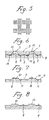
- On example of the pattern to arrange the impressions in the groups is shown in Fig. 5.
- each group of the impressions on the work roll surface is constituted by a plurality of impressions aligned in circumferential direction with a given intervals and axially arranged in a given pitch.
- temper rolling operation is performed.
- the uneven pattern formed on the work roll surface is transferred to the steel plate surface through the process shown in Fig. 6.
- the work roll 3 depresses the steel plate surface.
- the portion of the steel plate which mates with the annular projection 2 of the impression is depressed to form the annular groove 11 with rounded taper section 13 sending toward the top of the conico-cylindrical projection 10.
- the material causes plastic flow of fiber toward the portion mating the depression 1 of the impression of the work roll 3, as shown by arrow in Fig. 6. Therefore, the conico-cylindrical projection 10 with a flat top surface 8 is formed.
- the configuration of the uneven dot to be formed on the steel plate 7 is not specified to the configuration shown in Fig. 7.
- the configuration of the uneven dot to be formed during the temper rolling process becomes to have only conico-cylindrical projection as shown in Fig. 80.
- the steel plate which is formed the predetermined uneven pattern through the temper rolling process is then subject surface treatment, as shown Fig. 9.
- the surface treatment is performed by tin plating, chromium plating or galvanization to provide corrosion resistance and weather resistance for the steel plate.
- the uneven pattern on the surface of the steel plate becomes definite to provide good decorative appearance.
- transparent resin coating layer may be formed on the plating layer so as to further provide better corrosion resistance and weather resistance for the steel plate.
- the steel plate formed with the uneven pattern in the preferred process as set forth above since the steel plate formed with the uneven pattern in the preferred process as set forth above, has greater flat area than that of the steel plate which is formed uneveness on the surface by way of shot blasting or electric spark erosion surface area becomes smaller than that of the latters. As a result, required amount of the plating material becomes smaller. In other words, with the equal amount of the plating material, the steel plate according to the present invention can be formed thicker plating layer. This clearly provides better corrosion resistance and weather resistance in comparison with that treated by shot blasting or spark hardening. Furthermore, as is well shown, in case of electro-plating, intensity of plating current becomes higher at the projecting portion than that in the general section or depression.
- the thickness of the plating layer in various section becomes: T1) ⁇ T2 > T3 where T1 is thickness of plating layer at the top 8 of the conico-cylindrical projection 10; T2 is a thickness of the plating layer at the general surface section 9; and T3 is a thickness of the plating layer at the depression 11.
- This variation of thickness of the plating layer at various sections of the uneven dot provide advantage in exhibiting better corrosion resistance, weather resistance and in addition, wear resistance, since the top of the projection tends to be exposed to the environment. For instance, when such steel plate is used for forming a steel container, the top 8 of the conico-cylindrical projection tends to contact with the content in the container to subject wearing. This also prevents the bear material of the steel plate from being exposed and thus provide better rust-proof effect.
- Fig. 10 shows dimensional relationship of each impression to be formed on the work roll.
- the external diameter of the annular projection 2 which defines the border between the impression and the general surface section and thus defines the diametrical size of the impression, is D ⁇ m and the depth from of the depression is H ⁇ m.
- the diameter D is increased, the depth H of the depression is also increased.
- magnitude of increase of the depth becomes significant.
- temper rolling is performed for shape correction and and surface tempering.
- relatively high pressure should be exerted between the work roll and the steel plate. This leads higher transfer rate of the impression onto the steel plate surface. Therefore, when the diameter of the impression is large and thus the depth of the impression becomes deep, the conico-cylindrical projection to be formed on the steel plate surface becomes substantially high.
- greater amount of plastic material flow is required. Therefore, when the height of the projection to be formed is excessively high, substantially small defects tends to be formed around the projection.
- the maximum diameter of the impression is set at 300 ⁇ m.
- the minimum diameter of the impression is set at 10 ⁇ m.
- the uneven pattern on the steel plate will not be recognized by the size of the uneven dot to be formed but by density of the uneven dots and presence or absence thereof. Therefore, substantially height of the uneven dot is not required.
- the relative area ⁇ (%) of the impression can be defined by the diameter D of the impression and the center-to-center distance Sm ⁇ m between adjacent impressions.
- the relative area ⁇ csn be given by the following equation: In case Sm ⁇ D
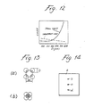
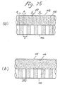
- sample pieces having size of 100 mm ⁇ 100 mm The sample piece is shown in Fig. 14.
- a denotes general surface section
- b , c and d shows sections in which impressions are formed. Size of the sections b , c and d are respectively 0.5 mm ⁇ 0.5 mm, 1.0 mm ⁇ 1.0 mm and 1.5 mm ⁇ 1.5 mm.
- samples pieces having mutually different surface roughness Ra in the sections a were prepared. The surface roughness Ra of respective sample pieces were 0.05 ⁇ m, 0.13 ⁇ m, 0.25 ⁇ m, 0.35 ⁇ m and 0.45 ⁇ m.
- the relative area ⁇ were varied to 100%, 80%, 55%, 30% and 10%. Therefore, total 25 different combinations in surface roughness and relative area, of sample pieces were provided for testing definiteness of the uneven pattern.
- recognition test was performed. In the recognition test, three tester having sight of 1.0 to 1.5 performed the test to see whether the uneven pattern formed on respective sample piece can be recognized or not, under a 200 lux of illumination and at a distance of 30 cm. from the sample pieces.
- Fig. 15 The result of the recognition test is shown in Fig. 15.
- the vertical axis represents the relative area ⁇ of the uneven dots and the horizontal axis represents the surface roughness Ra of the general surface section.
- the sign o indicates that all three tester recognized
- the sign ⁇ indicates that two among three testers recognized
- x indicates that non of tester recognized.
- the area ratio of the area occupied by the uneveness in the dulled section was 30% and the surface roughness of the general section where uneveness is not formed, was 0.40 ⁇ m.
- the result of the recognition test performed under the foregoing condition is shown in the appended table 1. As seen from the appended table 1, when the width of the general section interpositioned between the dulled sections is greater than or equal to 1 mm, dulled section could be recognized.
- the uneven pattern formed on the temper roll is shown in Figs. 17, 18 and 19.
- the temper roll prepared as above was set in a final stand of double-stand temper rolling mill. Temper rolling was then performed for a steel coil of the size 0.20 ⁇ 794 mm at a draft of 1.3%. Uneven pattern transfer rate was 98%. The uneven dot formed on the steel coil through the temper rolling process, had surface roughness Ra of 1.18 ⁇ m. After temper rolling process, the coil was separated into two pieces. One of the pieces was thereafter process by tin plating to make an electrolytic tin plate of 5.6 g/m2. For the other piece, chromium plating was performed to make an electrolytic chromium plate 130 mg/m2. In either case, clear uneven patterns could be recognized after plating process.
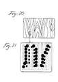
- the graining uneven pattern was formed by non-linear lines defined by impressions arranged along the line with area ratio of 55%.
- the distance between the lines are set greater than or equal to 1 mm.
- the temper roll thus prepared was set in a single stand temper rolling mill for performing temper rolling for annealed stainless steel (SUS304) with draft of 1.0%. Observing the resultant patterned stainless steel plate, no defect in the transferred graining uneven pattern at the surface side and the reverse or back side surface was maintained substantially plane. Furthermore, as observed, the graining pattern formed on the surface of the stainless steel plate was definite.
- the temper roll with the uneven pattern constituted by a plurality of impressions, each of which had depth of 120 ⁇ m With this temper roll, temper rolling was performed for the material steel strip same as that used in the foregoing example 1 was performed in substantially the same process.
- the resultant steel plate has uneveness on the back side.
- the uneven pattern transferred on the surface side was not satisfactorily definite.
- the temper roll with graining uneven pattern was prepared, which graining uneven pattern was formed by photo-etching process to have depth of 120 ⁇ m in each impression.
- the non-linear lines in the graining uneven pattern formed on the temper roll project from the general surface.
- the metal plate with the uneven pattern formed according the preferred process according to the present invention can exhibit excellent appearance with high corrosion resistance and weather resistance.
- the uneven pattern on the work roll tends to be transferred on the peripheral surface of a back-up roll and/or an intermediate roll since the back-up roll is pressed onto the peripheral surface of the work roll.
- the uneven pattern formed on the back-up roll and/or the intermediate roll is transferred to the work roll through the temper rolling process to overlap with the desired uneven pattern. This overlapping uneven pattern will be transferred from the work roll to the metal strip to degrade the quality of the uneven patterned metal strip and the appearance thereof.
- grinding process is performed for the back-up roll and/or the intermediate roll for removing the surface portion or outer skin portion of the rolls by means of sand-paper, whetstone and so forth.
- the temper rolling mill is necessarily stopped. This apparently lower efficiency.
- the uneveness on the peripheral surfaces of the back-up roll and/or the intermediate roll are relatively deep, the uneven portion on the surface of the rolls cannot be removed completely even by the grinding process.
- the present invention additionally provides a method and apparatus for avoiding the aforementioned defects and thus for maintain satisfactorily high efficiency and high yield in production of satisfactorily high quality patterned metal strip or plate.
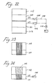
- Fig 22 shows the first embodiment of a four-roll type temper rolling mill to implement the preferred process for forming the uneven pattern on the metal strip.
- the four-stand type temper rolling mill comprises the work rolls 100 which is formed with the uneven pattern through the laser dulling process as set forth above.
- the stripe uneven pattern having a plurality of stripe lines extending circumferentially, is formed on the work roll surface.
- the stripe lines are formed in parallel to each other and spaced away from the adjacent stripe lines with a given distance b mm.
- the temper rolling mill also has a back-up rolls 102 which provide back pressure for respectively corresponding work roll.
- the work rolls 100 are associated with hydraulic cylinders 104.
- the hydraulic cylinders 104 are respectively designed to drive the corresponding work rolls 100 in axial direction.
- the shifting magnitude a mm of the work roll 100 is so selected as to be greater than or equal to half of the distance b mm between the stripe lines, each of which is formed by the dulled section.
- the hydraulic cylinders 104 are cyclically and synchronously driven for causing axial shift by a predetermined distance. In the alternative, it may be possible to continuously drive the work roll for axial shifting.
- the work roll 100 is no shifted in axial direction throughout the temper rolling mill operation.
- the uneven stripe pattern is transferred onto the back-up roll surface through the temper rolling operation, as shown in Fig. 23.
- the relatively wide range of depressed section 106 is formed on the back-up roll, as shown in Fig. 24. This makes the depth over the depressed section 106 substantially even. Therefore, it becomes unnecessary to perform grinding process even when the work roll is changed.
- the hydraulic cylinder 104 is connected to a pressurized working fluid source via a pressure line 108.
- a three-way flow control valve 110 may be provided in the pressure line 108 for adjusting the fluid pressure for driving the work roll 100 in the axial direction.
- the drive speed of the hydraulic cylinder 104 in axial direction is substantially lower in comparison with the line speed of the metal strip.
- the speed of axial shifting of the work roll is so selected as to be about 1/1000 of the line speed. Therefore, the offset of the stripe lines of the uneven pattern formed on the metal strip is not noticable. Consequently, the hydraulic cylinder 104 is driven continuously to continuously shifting the work roll in axial direction.
- the shifting magnitude a mm of the work roll 100 is necessarily greater than the axial width b mm of the interval between stripe lines.
- the shifting magnitude a mm is smaller than half of the width b mm of the interval, non-deformed section 112 in a width c mm (b/2(mm) - a(mm)) will be remained, as shown in Fig. 25(a).
- This uneven pattern tends to be transferred to the work roll.
- the shifting magnitude a mm of axial shift of the work roll 100 must be greater than b/2 mm.
- the hydraulic cylinder 104 was continuously driven to thrustingly shift the work roll so that the uneven pattern formed on the metal strip forms sin curve.
- the one cycle of thrusting shift of the work roll was set for 1000 m of the metal strip length.
- the temper rolling was performed at a line speed of 500 mpm.
- Fig. 26 shows another embodiment of the temper rolling mill to implement the preferred temper rolling process according to the present invention.
- the shown embodiment is directed to six-roll type temper rolling mill including a pair of work rolls 100, a pair of back-up rolls 102 and a pair of intermediate rolls 114.
- the hydraulic cylinders 104 are associated with the intermediate rolls 104 for driving the latter to cause axial shifting.
- the uneven pattern on the work roll 100 is transferred to the intermediate roll 114 and subsequently to the back-up roll 102. Therefore, when all of the work roll 100, the intermediate roll 114 and the back-up roll 104 are maintained in fixed relationship to each other, the uneven patterns as shown in Fig. 27 will be formed on the intermediate roll 114 and the back-up roll 104. In this case, when the work roll is changed to change the uneven pattern to be formed on the metal strip, the uneven pattern on the back-up roll 104 and the intermediate roll 114 is necessarily transferred to the work roll. Therefore, the uneven pattern of the former work roll overlaps with the desired uneven pattern of the current work roll. This apparently degrade the appearance of the metal plate to be formed.
- This defect can be eliminated by shifting one of the work roll and the intermediate roll in axial direction to make the rate of formation of uneveness on the intermediate roll and back-up roll even through overall periphery. Namely. by shifting the intermediate roll 114, the uneveness to be formed on the intermediate roll becomes at substantially even height through overall surface, as shown in Fig. 28. This uneveness is transferred to the back-up roll to transfer the uneven pattern. Therefore, since the intermediate roll surface and the back-up roll surface are maintained substantially plane, grinding process or replacement of the back-up roll and/or the intermediate roll upon changing of the uneven pattern to form on the metal strip, becomes unnecessary.
- the shifting magnitude a mm of the intermediate roll 114 is necessarily greater than the axial width b mm of the interval between stripe lines.
- the shifting magnitude a mm is smaller than half of the width b mm of the interval, non-deformed section 112 in a width c mm (b/2(mm) - a(mm)) will be remained, as shown in Fig. 29(a).
- This uneven pattern tends to be transferred to the work roll.
- the shifting magnitude a mm of axial shift of the intermediate roll 114 must be greater than b/2 mm.
- the hydraulic cylinder 104 was continuously driven to thrustingly shift the intermediate roll so that the uneven pattern formed on the metal strip forms sin curve.
- the one cycle of thrusting shift of the intermediate roll was set for 800 m of the metal strip length.
- the temper rolling was performed at a line speed of 500 mpm.
- the temper rolling mill according to the present invention provide easy maintenance of the intermediate roll and the back-up roll and expand the life of the rolls since no grinding process may be performed for long duration.
Landscapes
- Engineering & Computer Science (AREA)
- Mechanical Engineering (AREA)
- Metal Rolling (AREA)
- Reduction Rolling/Reduction Stand/Operation Of Reduction Machine (AREA)
- Finishing Walls (AREA)
Applications Claiming Priority (4)
| Application Number | Priority Date | Filing Date | Title |
|---|---|---|---|
| JP31060186A JPS63165011A (ja) | 1986-12-25 | 1986-12-25 | 模様鋼板及びその製造方法 |
| JP310601/86 | 1986-12-25 | ||
| JP187346/87 | 1987-07-27 | ||
| JP62187346A JPS6422401A (en) | 1987-04-22 | 1987-07-27 | Skin-pass rolling for patterned steel sheet |
Publications (2)
| Publication Number | Publication Date |
|---|---|
| EP0273402A2 true EP0273402A2 (de) | 1988-07-06 |
| EP0273402A3 EP0273402A3 (de) | 1991-10-16 |
Family
ID=26504299
Family Applications (1)
| Application Number | Title | Priority Date | Filing Date |
|---|---|---|---|
| EP19870119170 Withdrawn EP0273402A3 (de) | 1986-12-25 | 1987-12-23 | Blech mit Oberflächentextur und dessen Herstellung |
Country Status (4)
| Country | Link |
|---|---|
| US (1) | US4978583A (de) |
| EP (1) | EP0273402A3 (de) |
| KR (1) | KR950009137B1 (de) |
| AU (1) | AU604816B2 (de) |
Cited By (5)
| Publication number | Priority date | Publication date | Assignee | Title |
|---|---|---|---|---|
| DE4308809A1 (de) * | 1993-03-19 | 1994-09-22 | Daimler Benz Ag | Texturiertes Tiefziehblech |
| US5537851A (en) * | 1993-01-05 | 1996-07-23 | Aluminum Company Of America | Sheet product produced by massive reduction in last stand of cold rolling process |
| WO2016034813A1 (fr) | 2014-09-05 | 2016-03-10 | Constellium Neuf-Brisach | Procédé de fabrication de capsules de bouchage métalliques mixtes texturées lisses |
| WO2021078524A1 (de) * | 2019-10-23 | 2021-04-29 | Thyssenkrupp Steel Europe Ag | Verfahren zur oberflächenbearbeitung eines bleches und oberflächenbearbeitetes blech |
| DE102021200226A1 (de) | 2021-01-12 | 2022-07-14 | Thyssenkrupp Steel Europe Ag | Verfahren zur Herstellung einer texturierten Dressierwalze |
Families Citing this family (31)
| Publication number | Priority date | Publication date | Assignee | Title |
|---|---|---|---|---|
| CA2095228C (en) * | 1991-09-03 | 1997-01-14 | Takaharu Kawamoto | Steel strip having excellent painting sharpness and press moldability and method for producing rolling dull roll |
| US5328587A (en) * | 1992-11-16 | 1994-07-12 | Ir International, Inc. | Method of making machine-engraved seamless tube |
| US5508119A (en) * | 1994-09-07 | 1996-04-16 | Aluminum Company Of America | Enhanced work roll surface texture for cold and hot rolling of aluminum and its alloys |
| US6832547B2 (en) | 1996-10-16 | 2004-12-21 | Fort James Corporation | Embossing system including sleeved rolls |
| US5970771A (en) * | 1998-07-10 | 1999-10-26 | Danieli United | Continuous spiral motion system for rolling mills |
| US6261702B1 (en) * | 1999-05-21 | 2001-07-17 | J&L Specialty Steel, Inc. | Embossed rolled steel and embossing roll and method for making the same |
| US6344100B1 (en) | 1999-09-29 | 2002-02-05 | Robert A. Hipskind | Method of resurfacing a roll |
| US6807836B2 (en) | 2001-10-09 | 2004-10-26 | Ormet Corporation | Method of applying a surface finish on a metal substrate and method of preparing work rolls for applying the surface finish |
| JP2004001925A (ja) * | 2002-05-30 | 2004-01-08 | Shikahama Seisakusho:Kk | シート送りローラ |
| US20040040145A1 (en) * | 2002-08-29 | 2004-03-04 | Halliday James W. | Method for making a decorative metal sheet |
| ATE527073T1 (de) * | 2004-12-03 | 2011-10-15 | Novelis Inc | Prägewalzen von diskreten merkmalen |
| CN102004417A (zh) * | 2005-11-02 | 2011-04-06 | 精工爱普生株式会社 | 调色剂颗粒承载辊、以及显影装置 |
| ITFI20060072A1 (it) * | 2006-03-15 | 2007-09-16 | Perini Fabio Spa | Rullo goffratore e relativo procedimento per la sua produzione |
| JP4816413B2 (ja) * | 2006-11-07 | 2011-11-16 | セイコーエプソン株式会社 | 現像ローラの製造方法、現像装置および画像形成装置 |
| KR101100051B1 (ko) * | 2006-12-18 | 2011-12-29 | 제이에프이 스틸 가부시키가이샤 | 강대의 조질 압연 방법 및 고장력 냉연 강판의 제조 방법 |
| US8086152B2 (en) * | 2007-05-30 | 2011-12-27 | Seiko Epson Corporation | Developing device, image forming apparatus, image forming system, developing method, and toner bearing member |
| ES2706286T3 (es) * | 2007-07-17 | 2019-03-28 | Essity Operations Mannheim GmbH | Estampado en 3D |
| GB2454820B (en) * | 2007-11-13 | 2009-10-07 | Hadley Ind Overseas Holdings L | Sheet material |
| WO2010017289A1 (en) | 2008-08-05 | 2010-02-11 | Alcoa Inc. | Metal sheets and plates having friction-reducing textured surfaces and methods of manufacturing same |
| US20100078416A1 (en) * | 2008-09-26 | 2010-04-01 | Electro Scientific Industries | Method of laser micro-machining stainless steel with high cosmetic quality |
| US20100078418A1 (en) * | 2008-09-26 | 2010-04-01 | Electro Scientific Industries, Inc. | Method of laser micro-machining stainless steel with high cosmetic quality |
| US8567226B2 (en) * | 2008-10-06 | 2013-10-29 | GM Global Technology Operations LLC | Die for use in sheet metal forming processes |
| US9033030B2 (en) * | 2009-08-26 | 2015-05-19 | Munters Corporation | Apparatus and method for equalizing hot fluid exit plane plate temperatures in heat exchangers |
| DE102010025212A1 (de) * | 2010-06-23 | 2011-12-29 | Michael Weinig Ag | Transportwalze für den Vorschub von Werkstücken aus Holz, Kunststoff und dergleichen |
| EP2468493A1 (de) * | 2010-12-23 | 2012-06-27 | Boegli-Gravures S.A. | Vorrichtung zum Prägen von Folien |
| KR101657770B1 (ko) * | 2014-09-04 | 2016-09-20 | 주식회사 포스코 | 롤 표면처리 방법 및 장치 |
| EP3095882B1 (de) * | 2015-05-18 | 2021-09-22 | Outokumpu Oyj | Verfahren zur herstellung eines edelstahlblechs mit modifizierten visuellen eigenschaften |
| EP3362197A1 (de) * | 2015-10-14 | 2018-08-22 | Novelis, Inc. | Technisierte arbeitswalzentexturierung |
| EP3655174B1 (de) | 2017-07-21 | 2022-08-31 | Novelis Inc. | Mikrostrukturierte oberflächen durch niederdruckwalzen |
| CN109420680B (zh) | 2017-08-29 | 2020-11-17 | 宝山钢铁股份有限公司 | 用于钢板表面形貌轧制的轧辊及其制造方法 |
| DE102020102381A1 (de) * | 2020-01-31 | 2021-08-05 | Thyssenkrupp Rasselstein Gmbh | Verpackungsblecherzeugnis, insbesondere Weißblech oder elektrolytisch verchromtes Stahlblech und Verfahren zur Herstellung eines Verpackungsblecherzeugnisses |
Family Cites Families (18)
| Publication number | Priority date | Publication date | Assignee | Title |
|---|---|---|---|---|
| US2991544A (en) * | 1957-05-07 | 1961-07-11 | American Can Co | Bright surfaced metal sheets and method of producing same |
| DE1247251B (de) * | 1964-04-25 | 1967-08-17 | Opel Adam Ag | Ziehblech fuer Ziehteile |
| US3619881A (en) * | 1969-01-17 | 1971-11-16 | United States Steel Corp | Cold rolling work roll |
| FR2290623A1 (fr) * | 1974-11-06 | 1976-06-04 | Lorraine Laminage | Tole pour emboutissage profond ou extraprofond et procede d'obtention d'une telle tole |
| JPS548330A (en) * | 1977-06-21 | 1979-01-22 | Nihon Plast Co Ltd | Preparation of wooden handle |
| LU80792A1 (fr) * | 1979-01-15 | 1980-08-08 | Ntre De Rech Metallurg Ct Voor | Dispsitif et procede pour effectuer des perforations a la surface des cylindres de laminoirs |
| FR2476524A1 (fr) * | 1980-02-27 | 1981-08-28 | Sumitomo Metal Ind | Procede pour travailler la surface d'un cylindre de laminage a froid |
| DE3305067A1 (de) * | 1983-02-14 | 1984-08-16 | Hoechst Ag, 6230 Frankfurt | Platten-, folien- oder bandfoermiges material aus mechanisch und elektrochemisch aufgerauhtem aluminium, ein verfahren zu seiner herstellung und seine verwendung als traeger fuer offsetdruckplatten |
| LU85267A1 (fr) * | 1984-03-22 | 1985-10-14 | Centre Rech Metallurgique | Procede d'amelioration de l'etat de surface d'un cylindre |
| JPS61186103A (ja) * | 1985-02-14 | 1986-08-19 | Mitsubishi Heavy Ind Ltd | 圧延方法 |
| US4735883A (en) * | 1985-04-06 | 1988-04-05 | Canon Kabushiki Kaisha | Surface treated metal member, preparation method thereof and photoconductive member by use thereof |
| US4775599A (en) * | 1985-12-24 | 1988-10-04 | Kawasaki Steel Corporation | Cold rolled steel sheets having an improved press formability |
| US4798772A (en) * | 1986-01-17 | 1989-01-17 | Kawasaki Steel Corporation | Steel sheets for painting and a method of producing the same |
| AU573111B2 (en) * | 1986-01-17 | 1988-05-26 | Kawasaki Steel Corp. | Steel sheets for painting and a method of producing the same |
| JPS62230402A (ja) * | 1986-03-31 | 1987-10-09 | Kawasaki Steel Corp | 塗装用鋼板及びその製造方法 |
| JPS6311689A (ja) * | 1986-06-30 | 1988-01-19 | Kawasaki Steel Corp | Di缶用鋼板 |
| US4841611A (en) * | 1986-07-14 | 1989-06-27 | Kawasaki Steel Corporation | Work roll with dulled surface having geometrically patterned uneven dulled sections for temper rolling |
| LU86531A1 (fr) * | 1986-07-28 | 1988-02-02 | Centre Rech Metallurgique | Produit metallique presentant une brillance apres peinture amelioree et procedes pour sa fabrication |
-
1987
- 1987-12-22 US US07/136,729 patent/US4978583A/en not_active Expired - Fee Related
- 1987-12-23 EP EP19870119170 patent/EP0273402A3/de not_active Withdrawn
- 1987-12-24 KR KR1019870014855A patent/KR950009137B1/ko not_active Expired - Fee Related
- 1987-12-24 AU AU83037/87A patent/AU604816B2/en not_active Ceased
Cited By (6)
| Publication number | Priority date | Publication date | Assignee | Title |
|---|---|---|---|---|
| US5537851A (en) * | 1993-01-05 | 1996-07-23 | Aluminum Company Of America | Sheet product produced by massive reduction in last stand of cold rolling process |
| DE4308809A1 (de) * | 1993-03-19 | 1994-09-22 | Daimler Benz Ag | Texturiertes Tiefziehblech |
| WO2016034813A1 (fr) | 2014-09-05 | 2016-03-10 | Constellium Neuf-Brisach | Procédé de fabrication de capsules de bouchage métalliques mixtes texturées lisses |
| US10787295B2 (en) | 2014-09-05 | 2020-09-29 | Constellium Neuf-Brisach | Method of manufacturing textured-smooth hybrid metal closure caps |
| WO2021078524A1 (de) * | 2019-10-23 | 2021-04-29 | Thyssenkrupp Steel Europe Ag | Verfahren zur oberflächenbearbeitung eines bleches und oberflächenbearbeitetes blech |
| DE102021200226A1 (de) | 2021-01-12 | 2022-07-14 | Thyssenkrupp Steel Europe Ag | Verfahren zur Herstellung einer texturierten Dressierwalze |
Also Published As
| Publication number | Publication date |
|---|---|
| KR950009137B1 (ko) | 1995-08-16 |
| US4978583A (en) | 1990-12-18 |
| KR880007144A (ko) | 1988-08-26 |
| EP0273402A3 (de) | 1991-10-16 |
| AU8303787A (en) | 1988-06-30 |
| AU604816B2 (en) | 1991-01-03 |
Similar Documents
| Publication | Publication Date | Title |
|---|---|---|
| EP0273402A2 (de) | Blech mit Oberflächentextur und dessen Herstellung | |
| DE68910866T2 (de) | Verfahren und Vorrichtung zum Formen eines Mikro-Musters auf der Oberfläche einer Rolle, Metallbögen zum Pressarbeiten, durch die Rolle hergestellt und Verfahren zur Herstellung. | |
| US4329562A (en) | Method and device for improving the properties of thin steel plates | |
| DE69423784T2 (de) | Verfahren und vorrichtung zur herstellung von kaltgewalzten metallblechen oder -bändern, und daraus gewonnene metallbleche oder -bänder | |
| JP5694919B2 (ja) | 証券を生産するための凹版印刷版の製造の方法とシステム | |
| US4841611A (en) | Work roll with dulled surface having geometrically patterned uneven dulled sections for temper rolling | |
| DE60131034T3 (de) | Gekühlte giesswalze zum kontinuierlichen stranggiessen von dünnen produkten und stranggiessverfahren | |
| CA1280470C (en) | Laser beam machining device | |
| RU2144441C1 (ru) | Способ и устройство для производства металлических холоднокатаных листов или полос, полученные металлические листы или полосы | |
| DE3100927A1 (de) | Verfahren zur bearbeitung der oberflaeche einer walze fuer kaltwalzen, insbesondere einer dressierwalze und vorrichtung zur durchfuehrung dieses verfahrens | |
| EP1101561B1 (de) | Gravierverfahren und -vorrichtung für eine Flüssigkeitsübertragungsrolle mit Laserstrahlen | |
| JP2815493B2 (ja) | めっき浴用ロール | |
| JP4358524B2 (ja) | 冷間圧延用、搬送用、冷却クロムめっきロールおよびその製造方法並びに鋼板の製造方法 | |
| JPS6211922B2 (de) | ||
| CA1311946C (en) | Work roll for temper rolling a metal sheet | |
| AU619279B2 (en) | Process and equipment for micro-pattern forming on roll surface | |
| JP2667700B2 (ja) | シャドウマスク素材の製造方法 | |
| JPH082445B2 (ja) | 塗装鮮映性の優れた鋼板 | |
| AU643995B2 (en) | Metal sheets for pressworking prepared by a roll, and methods of preparing same | |
| JPH05161986A (ja) | レ−ザ−ダル加工方法 | |
| JPH01317604A (ja) | 冷間圧延用ワークロール |
Legal Events
| Date | Code | Title | Description |
|---|---|---|---|
| PUAI | Public reference made under article 153(3) epc to a published international application that has entered the european phase |
Free format text: ORIGINAL CODE: 0009012 |
|
| AK | Designated contracting states |
Kind code of ref document: A2 Designated state(s): AT BE DE ES FR GB IT NL SE |
|
| PUAL | Search report despatched |
Free format text: ORIGINAL CODE: 0009013 |
|
| AK | Designated contracting states |
Kind code of ref document: A3 Designated state(s): AT BE DE ES FR GB IT NL SE |
|
| 17P | Request for examination filed |
Effective date: 19920116 |
|
| 17Q | First examination report despatched |
Effective date: 19930323 |
|
| STAA | Information on the status of an ep patent application or granted ep patent |
Free format text: STATUS: THE APPLICATION IS DEEMED TO BE WITHDRAWN |
|
| 18D | Application deemed to be withdrawn |
Effective date: 19930803 |