EP0273466A2 - Flugzeug - Google Patents
Flugzeug Download PDFInfo
- Publication number
- EP0273466A2 EP0273466A2 EP87202043A EP87202043A EP0273466A2 EP 0273466 A2 EP0273466 A2 EP 0273466A2 EP 87202043 A EP87202043 A EP 87202043A EP 87202043 A EP87202043 A EP 87202043A EP 0273466 A2 EP0273466 A2 EP 0273466A2
- Authority
- EP
- European Patent Office
- Prior art keywords
- airplane
- wing
- control
- high efficiency
- aircraft
- Prior art date
- Legal status (The legal status is an assumption and is not a legal conclusion. Google has not performed a legal analysis and makes no representation as to the accuracy of the status listed.)
- Ceased
Links
Images




Classifications
-
- B—PERFORMING OPERATIONS; TRANSPORTING
- B64—AIRCRAFT; AVIATION; COSMONAUTICS
- B64C—AEROPLANES; HELICOPTERS
- B64C3/00—Wings
-
- B—PERFORMING OPERATIONS; TRANSPORTING
- B64—AIRCRAFT; AVIATION; COSMONAUTICS
- B64C—AEROPLANES; HELICOPTERS
- B64C3/00—Wings
- B64C3/18—Spars; Ribs; Stringers
- B64C3/185—Spars
-
- B—PERFORMING OPERATIONS; TRANSPORTING
- B64—AIRCRAFT; AVIATION; COSMONAUTICS
- B64C—AEROPLANES; HELICOPTERS
- B64C5/00—Stabilising surfaces
-
- B—PERFORMING OPERATIONS; TRANSPORTING
- B64—AIRCRAFT; AVIATION; COSMONAUTICS
- B64C—AEROPLANES; HELICOPTERS
- B64C1/00—Fuselages; Constructional features common to fuselages, wings, stabilising surfaces or the like
- B64C2001/0018—Fuselages; Constructional features common to fuselages, wings, stabilising surfaces or the like comprising two decks adapted for carrying passengers only
- B64C2001/0036—Fuselages; Constructional features common to fuselages, wings, stabilising surfaces or the like comprising two decks adapted for carrying passengers only arranged side by side at the same level
-
- B—PERFORMING OPERATIONS; TRANSPORTING
- B64—AIRCRAFT; AVIATION; COSMONAUTICS
- B64C—AEROPLANES; HELICOPTERS
- B64C1/00—Fuselages; Constructional features common to fuselages, wings, stabilising surfaces or the like
- B64C2001/0045—Fuselages characterised by special shapes
-
- B—PERFORMING OPERATIONS; TRANSPORTING
- B64—AIRCRAFT; AVIATION; COSMONAUTICS
- B64C—AEROPLANES; HELICOPTERS
- B64C1/00—Fuselages; Constructional features common to fuselages, wings, stabilising surfaces or the like
- B64C2001/0054—Fuselage structures substantially made from particular materials
- B64C2001/0072—Fuselage structures substantially made from particular materials from composite materials
-
- Y—GENERAL TAGGING OF NEW TECHNOLOGICAL DEVELOPMENTS; GENERAL TAGGING OF CROSS-SECTIONAL TECHNOLOGIES SPANNING OVER SEVERAL SECTIONS OF THE IPC; TECHNICAL SUBJECTS COVERED BY FORMER USPC CROSS-REFERENCE ART COLLECTIONS [XRACs] AND DIGESTS
- Y02—TECHNOLOGIES OR APPLICATIONS FOR MITIGATION OR ADAPTATION AGAINST CLIMATE CHANGE
- Y02T—CLIMATE CHANGE MITIGATION TECHNOLOGIES RELATED TO TRANSPORTATION
- Y02T50/00—Aeronautics or air transport
- Y02T50/10—Drag reduction
-
- Y—GENERAL TAGGING OF NEW TECHNOLOGICAL DEVELOPMENTS; GENERAL TAGGING OF CROSS-SECTIONAL TECHNOLOGIES SPANNING OVER SEVERAL SECTIONS OF THE IPC; TECHNICAL SUBJECTS COVERED BY FORMER USPC CROSS-REFERENCE ART COLLECTIONS [XRACs] AND DIGESTS
- Y02—TECHNOLOGIES OR APPLICATIONS FOR MITIGATION OR ADAPTATION AGAINST CLIMATE CHANGE
- Y02T—CLIMATE CHANGE MITIGATION TECHNOLOGIES RELATED TO TRANSPORTATION
- Y02T50/00—Aeronautics or air transport
- Y02T50/40—Weight reduction
Definitions
- the present invention relates to novel, improved aircraft which are aerodynamically efficient and relatively simple in terms of operation, structure, systems, and mechanisms and are consequently quieter and more economical to design, build, operate, and maintain than currently existing aircraft and those now coming into existence. Included in manufacturing and operating costs, in the this respect, are such indirect factors as the skill required to fly the aircraft and the ability of the aircraft to accommodate and/or survive adverse weather conditions as well as wind shear, gusts, and other phenomena which are inimical to the operation of an aircraft and the safety and comfort of the aircraft's passengers and/or crew.
- the present invention relates to a flight control methodology which takes full advantage of state-of-the-art computer technology and thereby makes possible aircraft with the desirable attributes identified in the preceding paragraph.
- a related disadvantage is that the trailing edge control members of conventional aircraft are so designed and operated that large loads are imposed on the wing at significant distances from the aircraft body. These loads can cause unwanted wing bending; they can also make rapid pull-ups unsafe.
- a plot of the cross-sectional areas of a conventionally designed aircraft is an irregular curve with several sharp peaks. In practical terms, this means that the performance of the aircraft and its handling characteristics will suffer as the aircraft approaches the speed of sound, primarily because of the generation of shock waves
- Airplanes embodying the foregoing flight control methodology have a number of interrelated advantages.
- the pitching down of the aircraft when the trailing edge control segments are deflected upwardly to decrease lift complements rather than opposes that action of the control segments.
- the trailing edge control members can be made to function with high efficiency in the same manner as conventional spoilers, eliminating the need for spoilers and complexity and problems appurtenant to the spoilers of conventional aircraft.
- Trailing edge control segments which have a split construction and which extend beneath the aircraft body when lowered are preferably employed in the novel aircraft disclosed herein.
- One advantage of such control segments is that they enhance dive recovery because they provide additional drag plus lift; and the lift can be provided without making a necessarily slower attitude change.
- this fully active system of trailing edge control members eliminates the need for stabilizer trim as is required in existing aircraft. This reduces pilot workload and the skill needed to fly the airplane and leads to simplification because the nonactive sections of the empennage need not be movable with respect to the airplane body.
- the coefficient of lift can be controlled primarily by management of the trailing edge control segments rather than with alterations of aircraft attitude as it is in conventional aircraft. This, particularly if a preferred variable gain of the control segments is employed, makes the aircraft disclosed herein much less sensitive to gusts and wind shear than a conventional airplane. Also, the loads and bending moments imposed on the wing can be concentrated near the aircraft body where they can be more readily accommodated. This makes it possible to realize a significant cost savings as a simpler and lighter wing can be employed.
- Stall recovery of the novel airplanes disclosed herein is significantly superior.
- the raising or upward deflection of the trailing edge control surfaces reduces the lift coefficient and thereby instantly eliminates separated flow so that the airplane is no longer stalled. Rapid stall recovery is further promoted by the flight control methodology disclosed herein because the reduction in lift produced by raising the control segments pitches the aircraft downwardly, further reducing the lift coefficient and contributing to the recovery of flying speed.
- the full span, fully active system of primary trailing edge control segments may make it possible to eliminate the spoilers and/or leading edge devices necessarily employed in existing high speed aircraft for air braking and for roll control.
- Another advantage of aircraft employing the flight control methodology disclosed herein is that, if attention is payed to the details of the aircraft configuration, "trimming" of the airplane can be eliminated as a conscious control function.
- the center of gravity is shifted aft in the aircraft disclosed herein by: (1) employing a wing which has a much higher aspect ratio than the wing of a conventionally designed aircraft; and (2) by locating the cargo and passenger compartments, engines, and main landing gear toward the rear of the aircraft.
- a wide, preferably double lobe body will typically be employed. This configuration lends itself to sought after, eight abreast seating and to mixed loads of passengers and cargo.
- the width afforded by the double lobe configuration also separates the aft mounted engines by an amount which is significantly greater than is the case in a conventional airplane design. This shifts the aerodynamic center of the airplane to the extent that the engines pay their own way aerodynamically; i.e., aerodynamically, the engines support their own weight.
- the width of the double lobe configuration also affords the freedom needed in locating the landing gear so that the aircraft center of gravity will be in the optimum location.
- main landing gear Another advantage of the relatively far aft location of the main landing gear is that it thereby becomes relatively simple to make those landing gear steerable. Steerable main landing gear facilitate cross-wind landings and makes the airplane easier to handle on the ground.
- This preferred location of the landing gear also allows relatively short landing gear struts to be employed. This is important as it simplifies the landing gear, making another significant cost reduction possible.
- aircraft employing the flight control methodology disclosed herein can be significantly simpler than their present day counterparts. Because of reduced drag, for example, they are also quieter than existing aircraft and those coming into existence.
- composite wing construction disclosed herein has no joints and no fasteners in areas of maximum stress. Higher stresses are therefore allowable.
- a multi-spar construction which has low fail-safe penalties is used; and internal ribs are eliminated, producing a significant cost saving as does the low part card count of this construction.
- wing inspection can be accomplished without providing the access doors required for inspection purposes in conventional designs.
- an airplane embodying my novel design principles has an envelope of cross-sectional areas which is relatively smooth and characterized by a minimum of sharp peaks.
- the performance and handling characteristics of the airplane are superior to those of a more conventional one at speeds approaching the speed of sound.
- Another important and primary object of my invention is the provision of aircraft which require less skill to fly, impose a lower workload on the pilot, and are otherwise safer to fly than conventional ones in that: (1) the added lift required as speeds are slowed during landing approaches can be obtained without rotating the airplane into an attitude which restricts the pilot's visibility, and (2) the flight methodology employed makes them less susceptible to gusts and wind shear and speeds stall and dive recovery.
- Yet another important and primary object of the present invention is the provision of a novel, improved flight control methodology which takes full advantage of state-of-the-art computer technology and thereby makes possible aircraft with the desirable attributes identified in the preceding objects.
- Still other important but more specific objects of my invention reside in the provision of airplanes in accord with the preceding objects: in which all flight controls are active; in which all flight control surfaces or elements are primary; in which a series of control segments at the trailing edge of, and spanning, the aircraft wing replaces the complicated system of flaps, spoilers, and ailerons and other primary and secondary control surfaces of modern aircraft; in which, in conjunction with the preceding object, the several control segments are computer-operated in accord with schedules which both control the coefficient of lift and the roll of the aircraft; which have a wing with a higher aspect ratio than is employed in existing passenger and cargo aircraft and those coming into existence; in which the center of gravity is significantly further aft than it is in a more conventional airplane; in which, in conjunction with the preceding object, the center of gravity is sufficiently far aft that lowering the trailing edge control surfaces will induce pitch-up moments while the raising of those control surfaces will cause pitch-down moments so that the change in attitude of the airplane will complement and enhance the lift coefficient changing action of the
- FIGS. 1-3 depict an airplane 20 constructed in accord with, and embodying, the principles of the present invention.
- aircraft 20 The major components of aircraft 20 include a body 22 of double lobe configuration (see FIG. 4); swept back wing 24 of high aspect ratio located at the bottom of aircraft body 22; a V-type empennage 25 including two members 26 and 27 with active control surfaces 28 and 29; and two propulsion units 30 and 32 supported from opposite sides of aircraft body 22 immediately ahead of empennage 25 by aerodynamic struts 33 and 34.
- the double lobe body 22 of aircraft 20 is divided by a vertical partition 36 into two compartments 38 and 40 for passengers or cargo or for a mixture of passengers and cargo. Each of these compartments has a ceiling 42 or 44, and there is a floor 46 with two additional cargo compartments 48 and 50 located therebeneath.
- the double lobe body configuration shown in FIG. 4 is preferred because it lends itself to the highly desirable eight abreast seating arrangement.
- Four of the seats (identified by reference characters 55...58 in FIG. 4) can be located in each of the compartments 38 and 40.
- the cargo will first be loaded into containers designed to fit into upper compartments 38 and/or 40 and lower compartments 48 and 50.
- Exemplary containers are shown in FIG. 4 and identified by reference characters 59, 60a, and 60b.
- the passengers and cargo are located in the aft part of the aircraft body insofar as this is possible in order to keep the center of gravity of the loaded aircraft well rearward of the location it would assume in a conventional design.
- the rearmost section 61 of the aircraft body is preferably constructed so that it can be swung aside.
- the two propulsion units 30 and 32 of aircraft 20 will typically be fan jets of a state-of-the-art design. Neither the details of these engines nor the struts supporting them from aircraft body 22 are part of the present invention. Consequently, those components of aircraft 20 will not be described further herein.
- Empennage 25 is likewise of a construction which does not need to be described in detail herein because that construction is not part of my present invention. It is believed sufficient to note that the control surfaces 28 and 29 of the empennage function as in other V-shaped tails to control both up-and-down movement of aircraft 20 and its heading.
- the members 26 and 27 of empennage 25 need not be trimmed. Consequently, the inactive sections 62 and 63 of the empennage need not be made movable with respect to aircraft body 22 as is necessary in a more conventional aircraft design. They can instead be attached in fixed fashion to the aircraft body. This is important from the viewpoints of simplification and cost reduction.
- the nose gear 64 of aircraft 20 may be of conventional construction and in a conventional location; and it has accordingly not been shown in the drawing.
- the main landing gear 64 is located behind wing 24, again in the interest of keeping the center of gravity of airplane 20 well aft.
- the main landing gear retracts upwardly into the body 22 of aircraft 20.
- the body has a width capable of accommodating the main landing gear because of its preferred, double lobe configuration.
- This arrangement has the advantage that the main landing gear can readily be made steerable. Also, the posts (not shown) by which trucks 66 and 67 are supported are relatively short. This means that they can be made simpler and lighter because they need not withstand the larger bending moments and stresses imposed upon the longer struts of conventional airplanes.
- Another benefit of this high aspect ratio wing is that it leaves a space in which the main landing gear can be located independently of the wing structure.
- the center of gravity is related to the mean aerodynamic chord (MAC) of the airplane's wing.
- MAC mean aerodynamic chord
- the leading edge of the mean aerodynamic chord is zero percent MAC and the trailing edge of the chord is 100 percent MAC.
- the center of gravity is located at a fore-and-aft location which is between 44 percent MAC and 70 percent MAC. This places the center of lift of wing 24 well ahead of its center of gravity.
- this novel relocation of the airplane's center of gravity results in: (1) the aircraft tending to pitch up when the active control components at the trailing edge of wing 24 are lowered to increase the coefficient of lift of the aircraft; and (2) the aircraft pitching down to decrease lift when those control elements are raised to decrease the lift coefficient.
- the pitching moments imposed upon airplane 20 either increase or decrease lift in a manner which complements the action of the control elements rather than opposing that action as is the case in existing airplanes and those now coming into existence.
- a comparison of curve 77 with the second curve 78 in FIG. 10 also shows that the design of the empennage is important in the novel flight control methodology disclosed herein in that changes in the size of the tail members effects a definite shift in the center of gravity of the airplane being designed.
- airplane 20 can be assembled from a relatively small number of independently fabricated sections.
- the aircraft body 24 is made up of two upper, left and right sections 79 and 80; corresponding lower sections (the left-hand two of which are shown in FIG. 3 and identified by reference characters 82 and 84); a section 86 which is located behind those just identified and supports empennage 25 and propulsion units 30 and 32; the swing-away tail section 61; partition 36; floor 46; a rear bulkhead 87; and, at the opposite end of the aircraft, a cockpit section 88.
- Wing 24 is made up of left and right sections 90 and 92. However, as was indicated above, this wing may alternately be fabricated as a unitary or one-piece member.
- At least the wing 24 of airplane 20 is of a novel, composite structure which has the advantages discussed above including the elimination of internal ribs, the elimination of joints and fasteners in highly stressed areas, and a significant reduction in weight.
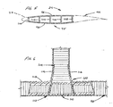
- This novel wing shown in detail in FIGS. 5 and 6, has a nose section 93; a full span series of juxtaposed, primary, active control members or segments identified collectively by reference character 94 in FIG. 5; and a main section 95.
- the main section 95 of wing 24 includes: (1) upper and lower panels 96 and 98 separated by spaced apart, longitudinally extending spars 100...108; (2) longitudinally extending stiffeners 110 at the panel/spar intersections to carry the bending moments imposed upon wing 24; and (3) an outer skin 112.
- This skin is typically composed of a layer of carbon reinforcing filaments wound in helical fashion around the main section 95 of wing 24 and longitudinally extending tapes laid in side-by-side relationship on the wound filament reinforcing.
- the upper and lower panels 96 and 98, the spars 100...108, and the stiffeners 110 are all of honeycomb construction. Like the upper and lower panels, the stiffeners are preferably wound with carbon filaments to increase their strength. Also, as is best shown in FIG. 6, fabric tapes 114, 116, and 118 are employed to increase the strength of the joint 120 between each panel 96 or 98 and spar 100...108.
- each of aircraft 20's left and right wing sections 90 and 92 there are a series of active, primary control surfaces or elements 122...134 at the trailing edge of each of aircraft 20's left and right wing sections 90 and 92. These control elements extend in side-by-side relationship from the center 142 of wing 24 to the left wing tip 144 and to the right wing tip 146.
- Each control element 122L...134L and 122R...134R is independently hinged for upward and downward pivotable movement about an axis extending longitudinally of the wing section 90 or 92 in which that segment is incorporated.
- An exemplary hinge axis, that for control element 128R, is located at the forward edge of the control element and is identified by reference character 148.
- the trailing edge control components serve two functions. They are utilized both to change the coefficient of lift of airplane 20 and to control the roll of the airplane.
- each trailing edge control component 122L...134L and 122R...134R is independently effected by a separate electric motor through a mechanical linkage which has not been depicted and will not be described herein because its details are not part of my present invention.
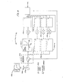
- These motors are shown diagrammatically in FIG. 8 and identified by reference characters 150-l...150-n.
- any desired type of electric motor may be employed. However, those employing samarium/cobalt permanent magnets are preferred because of their high torque-to-weight ratio, the elimination of brushes and commutators, and the ability to operate as a stalled motor while holding the control element in a fixed position.
- control elements 122L...134L and 122R...134R can be of any desired construction although a construction analogous to a split flap is preferred. As discussed above, this construction is preferred because of the enhanced dive recovery it provides as the control elements are deployed downwardly beneath the aircraft body.
- Trailing edge control elements 1-14 are incorporated in the wing 156 of an aircraft 158 of the character shown in detail in FIGS. 1-3 and illustrated diagrammatically in FIG. 12.
- control elements 7 and 8 and the adjacent elements 6 and 9 are employed solely to control the coefficient of lift of airplane 158.
- the coefficient of lift is increased to produce additional lift as these control elements are lowered and reduced to decrease lift in a manner akin to a spoiler as control elements 6 and 9 are raised (control elements 7 and 8 can of course not be raised as they are located directly beneath the body 160 of airplane 158).
- control elements 1-5 and 10-14 can also be lowered and raised to respectively increase and decrease the coefficient of lift of aircraft 158.
- the movement of these control elements is so scheduled that, proceeding from the body 160 of aircraft 158 toward its wing tips 162 and 164, each control element can be deployed only to a somewhat smaller (typically two degree) maximum.
- gain is employed herein to identify this staggered upward and downward deployment of the trailing edge control elements in airplanes embodying the principles of the present invention. Typically, this gain may range from 1.0 at the innermost control elements to 0.25 at those control elements located at the tips of the aircraft wings.
- this variable gain scheduling of the deployment of trailing edge control elements 1-14 concentrates the loadings on wing 156 nearer the body 158 of airplane 160 than is the case in a more conventional design. This is apparent from a comparison of curves 166 and 168 in FIG. 12.
- the loads and bending moments imposed on the wing can be more readily accommodated than they can at more outboard locations where more complex, and heavier, structures are required to accommodate the large loads and bending moments existent in conventional designs even at locations very near the tips of the aircraft wing.
- the novel flight control methodology disclosed herein offers both a much simplified wing construction and a significant cost reduction.
- the active, primary control elements of the subject aircraft operate to provide that relationship between lift coefficient and airplane attitude shown in the shaded area 170 in FIG. 13. This Figure makes it clear that the lift needed for both approaches and takeoffs can be readily obtained with only minor changes in the attitude of the aircraft and that the angle of attack is, in both takeoff and landing configurations, only a few degrees.
- the second shaded area 172 in FIG. 13 makes it clear that the changes of airplane attitude resulting from gusts can be quickly counteracted in the airplanes disclosed herein merely by raising the trailing edge control elements to decrease the lift coefficient of the airplane. Because these elements are operated directly by electric motors rather than through complicated control cable and/or hydraulic systems, this can be accomplished in a fraction of the time that would be required to effect a similar maneuver in a conventional airplane by manipulating its secondary flight controls.
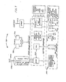
- FIG. 8 the system including motors 150-l...150-n and central processor 152 and employed for scheduling the operation of trailing edge control elements 122L...134L and 122R...134R (FIG. 2) or 1-14 (FIG. 11) is illustrated in FIG. 8 and identified by reference character 174.
- this system includes a controller 176-l...176-n for each of the control element operating motors 150-l...150-n.
- the flight path wanted by the airplane pilot is selected by pushing forward or pulling back on a conventional stick 178 as indicated by double-headed arrow 180 in FIG. 8.
- This information is inputted to central processor 152 which calculates the number of revolutions of each motor 150-l...150-n required to set the control elements operated by those motors at angles which will cause the airplane 20 (or 158) to assume the flight path selected by the pilot.
- This information is outputted to controllers 176-l...176-n which thereupon cause the controlled motors 150-l...150-n to make the appropriate number of revolutions in one direction to raise the control element operated by that motor and in the opposite direction to lower it.
- Positional information is fed back from the trailing edge control elements to both the motors 150-l...150-n and to central processor 152. These feedbacks are employed to make any minor adjustments in the positions of the trailing edge control elements that may be required to cause the aircraft to assume the pilot-selected flight path.
- the flight path followed by the aircraft is displayed on a screen 184.
- the just-described control system 174 is incorporated in a larger system 186 illustrated in FIG. 7 and employed to also control: (1) the active, primary control elements 28 and 29 of tail members 26 and 28; (2) the steering of main landing gear 64 and forward landing gear 65; and (3) the operation of engines 30 and 32.
- the inputs are from stick 178, left and right pedals 188 and 190, and throttle 192.
- the inputs from stick 178 (forward and back and left and right) are employed by central processor 152 to schedule the operation of the primary, active wing and tail control elements as discussed above.
- pedals 188 and 190 are utilized to operate the aircraft brakes (not shown) and to steer its main and forward landing gears 64 and 65. Again, control is exercised via central processor 152.
- Throttle 192 also operates in a somewhat conventional manner to control (through central processor 152) the speed of the airplane and the fan reversers typically incorporated in such engines to slow the aircraft after it lands. As shown in FIG. 7, the input from throttle 192 will also typically be employed by central processor 152 to raise the trailing edge control elements after the airplane has landed. This kills all lift and insures that the airplane remains on the ground.
- the central processor 152 of control system 186 will also typically receive such inputs as the altitude, velocity, acceleration, etc. of the airplane in which it is incorporated.
- Local processors associated with the primary control surfaces, landing gear, and engines will receive additional inputs such as those identified in block 194 of FIG. 7.
- the particular inputs which are provided and the manner in which they are employed are not part of my present invention; and these aspects of control system 186 will accordingly not be described herein.
Landscapes
- Engineering & Computer Science (AREA)
- Aviation & Aerospace Engineering (AREA)
- Mechanical Engineering (AREA)
- Toys (AREA)
- Control Of Position, Course, Altitude, Or Attitude Of Moving Bodies (AREA)
Applications Claiming Priority (2)
| Application Number | Priority Date | Filing Date | Title |
|---|---|---|---|
| US94831786A | 1986-12-31 | 1986-12-31 | |
| US948317 | 1986-12-31 |
Publications (2)
| Publication Number | Publication Date |
|---|---|
| EP0273466A2 true EP0273466A2 (de) | 1988-07-06 |
| EP0273466A3 EP0273466A3 (de) | 1990-05-09 |
Family
ID=25487646
Family Applications (1)
| Application Number | Title | Priority Date | Filing Date |
|---|---|---|---|
| EP87202043A Ceased EP0273466A3 (de) | 1986-12-31 | 1987-10-23 | Flugzeug |
Country Status (1)
| Country | Link |
|---|---|
| EP (1) | EP0273466A3 (de) |
Cited By (6)
| Publication number | Priority date | Publication date | Assignee | Title |
|---|---|---|---|---|
| US5086996A (en) * | 1989-07-12 | 1992-02-11 | Airbus Industrie | High-capacity fuselage for aircraft |
| ES2112711A1 (es) * | 1994-05-25 | 1998-04-01 | Torres Martinez M | Estructura para aviones. |
| WO2002030743A1 (en) * | 2000-10-13 | 2002-04-18 | Karklin, Andrei Mikhailovich | Aircraft provided with carrying fuselage |
| FR2884492A1 (fr) * | 2005-04-13 | 2006-10-20 | Airbus France Sas | Aeronef a faible bruit, notamment lors des decollages et des atterrissages. |
| EP0899189B2 (de) † | 1997-08-29 | 2009-10-21 | The Boeing Company | Schwenkbarer Zugbinder und Verriegelungseinrichtung |
| CN114560082A (zh) * | 2022-02-16 | 2022-05-31 | 西南科技大学 | 一种能有效控制桨尖涡的组合修形的桨尖结构及设计方法 |
Families Citing this family (1)
| Publication number | Priority date | Publication date | Assignee | Title |
|---|---|---|---|---|
| US8584921B2 (en) | 2006-10-06 | 2013-11-19 | Covidien Lp | Surgical instrument with articulating tool assembly |
Family Cites Families (6)
| Publication number | Priority date | Publication date | Assignee | Title |
|---|---|---|---|---|
| US2385845A (en) * | 1943-03-15 | 1945-10-02 | Boeing Aircraft Co | Aircraft with high-speed stability |
| GB913005A (en) * | 1960-10-24 | 1962-12-12 | Blackburn Aircraft Ltd | Improvements in and relating to doors for freight carrying aircraft |
| FR1460060A (fr) * | 1965-10-15 | 1966-06-17 | Nord Aviation | Fuselage de grande capacité et aérodyne correspondant |
| US3670995A (en) * | 1970-05-20 | 1972-06-20 | Swearingen Aviat Corp | Longitudinal stability control device for fixed wing aircraft |
| US3823899A (en) * | 1972-10-20 | 1974-07-16 | Lockheed Aircraft Corp | Actuation system for angularly positioning aircraft landing gear wheels |
| US4674712A (en) * | 1985-01-22 | 1987-06-23 | The Boeing Company | Double-lobe fuselage composite airplane |
-
1987
- 1987-10-23 EP EP87202043A patent/EP0273466A3/de not_active Ceased
Cited By (11)
| Publication number | Priority date | Publication date | Assignee | Title |
|---|---|---|---|---|
| US5086996A (en) * | 1989-07-12 | 1992-02-11 | Airbus Industrie | High-capacity fuselage for aircraft |
| ES2112711A1 (es) * | 1994-05-25 | 1998-04-01 | Torres Martinez M | Estructura para aviones. |
| EP0899189B2 (de) † | 1997-08-29 | 2009-10-21 | The Boeing Company | Schwenkbarer Zugbinder und Verriegelungseinrichtung |
| WO2002030743A1 (en) * | 2000-10-13 | 2002-04-18 | Karklin, Andrei Mikhailovich | Aircraft provided with carrying fuselage |
| US6834832B2 (en) | 2000-10-13 | 2004-12-28 | Stepan Grigoryevich Jamgarov | Aircraft provided with carrying fuselage |
| FR2884492A1 (fr) * | 2005-04-13 | 2006-10-20 | Airbus France Sas | Aeronef a faible bruit, notamment lors des decollages et des atterrissages. |
| WO2006108957A3 (fr) * | 2005-04-13 | 2006-12-14 | Airbus France | Aeronef a faible bruit, notamment lors des decollages et des atterrissages. |
| CN100564159C (zh) * | 2005-04-13 | 2009-12-02 | 法国空中巴士公司 | 特别是在起飞和降落时较小噪音的飞机 |
| US8074924B2 (en) | 2005-04-13 | 2011-12-13 | Airbus Operations Sas | Low-noise aircraft, particularly at take-off and landing |
| CN114560082A (zh) * | 2022-02-16 | 2022-05-31 | 西南科技大学 | 一种能有效控制桨尖涡的组合修形的桨尖结构及设计方法 |
| CN114560082B (zh) * | 2022-02-16 | 2023-07-04 | 西南科技大学 | 一种能有效控制桨尖涡的组合修形的桨尖结构及设计方法 |
Also Published As
| Publication number | Publication date |
|---|---|
| EP0273466A3 (de) | 1990-05-09 |
Similar Documents
| Publication | Publication Date | Title |
|---|---|---|
| US5088661A (en) | Aircraft | |
| US11639218B2 (en) | Tilting mechanism with telescoping actuator | |
| US6079672A (en) | Aileron for fixed wing aircraft | |
| US5086993A (en) | Airplane with variable-incidence wing | |
| Spillman | The use of variable camber to reduce drag, weight and costs of transport aircraft | |
| US7455264B2 (en) | Reconfiguration control system for an aircraft wing | |
| CN114126966A (zh) | 使用串联式机翼和分布式推进系统的新型飞行器设计 | |
| DE60210512T2 (de) | Senkrecht startendes und landendes flugzeug | |
| EP0084686B1 (de) | Flugzeug | |
| KR20200063073A (ko) | 적어도 8개의 추력 생성 유닛들을 구비한 수직 이륙 및 착륙 멀티로터 항공기 | |
| USRE36487E (en) | Airplane with variable-incidence wing | |
| KR20250055510A (ko) | 플랩을 포함한 덕트형 날개 | |
| US20180222584A1 (en) | Tandem Wing Aircraft With Variable Lift And Enhanced Safety | |
| US12503245B2 (en) | Fuselage for a convertible aircraft capable of hovering | |
| US8262017B2 (en) | Aircraft with forward lifting elevator and rudder, with the main lifting surface aft, containing ailerons and flaps, and airbrake | |
| US4003533A (en) | Combination airbrake and pitch control device | |
| WO2006022813A2 (en) | High-lift, low-drag dual fuselage aircraft | |
| US3938761A (en) | Aircraft with improved field of view for passengers | |
| Olason et al. | Aerodynamic design philosophy of the Boeing 737. | |
| RU2100253C1 (ru) | Сверхзвуковой самолет | |
| RU2028964C1 (ru) | Самолет вертикального взлета и посадки | |
| CN113859526A (zh) | 可垂直起降的固定翼飞机及其控制方法 | |
| DE102020107437A1 (de) | Luftfahrzeug mit 3-dimensionaler, aerodynamischer und multifunktionaler Ausführung | |
| RU229972U1 (ru) | Беспилотный летательный аппарат вертикального взлета и посадки | |
| US3093347A (en) | Convertible vtol aircraft |
Legal Events
| Date | Code | Title | Description |
|---|---|---|---|
| PUAI | Public reference made under article 153(3) epc to a published international application that has entered the european phase |
Free format text: ORIGINAL CODE: 0009012 |
|
| AK | Designated contracting states |
Kind code of ref document: A2 Designated state(s): DE FR GB IT NL |
|
| PUAL | Search report despatched |
Free format text: ORIGINAL CODE: 0009013 |
|
| AK | Designated contracting states |
Kind code of ref document: A3 Designated state(s): DE FR GB IT NL |
|
| 17P | Request for examination filed |
Effective date: 19901005 |
|
| 17Q | First examination report despatched |
Effective date: 19911011 |
|
| STAA | Information on the status of an ep patent application or granted ep patent |
Free format text: STATUS: THE APPLICATION HAS BEEN REFUSED |
|
| 18R | Application refused |
Effective date: 19940410 |
|
| RIN1 | Information on inventor provided before grant (corrected) |
Inventor name: WHITENER, PHILIP C. |