EP0273543A2 - Interaktive Spielvorrichtung - Google Patents
Interaktive Spielvorrichtung Download PDFInfo
- Publication number
- EP0273543A2 EP0273543A2 EP87307117A EP87307117A EP0273543A2 EP 0273543 A2 EP0273543 A2 EP 0273543A2 EP 87307117 A EP87307117 A EP 87307117A EP 87307117 A EP87307117 A EP 87307117A EP 0273543 A2 EP0273543 A2 EP 0273543A2
- Authority
- EP
- European Patent Office
- Prior art keywords
- weapon
- light
- score
- photosensor
- images
- Prior art date
- Legal status (The legal status is an assumption and is not a legal conclusion. Google has not performed a legal analysis and makes no representation as to the accuracy of the status listed.)
- Withdrawn
Links
Images




Classifications
-
- A—HUMAN NECESSITIES
- A63—SPORTS; GAMES; AMUSEMENTS
- A63F—CARD, BOARD, OR ROULETTE GAMES; INDOOR GAMES USING SMALL MOVING PLAYING BODIES; VIDEO GAMES; GAMES NOT OTHERWISE PROVIDED FOR
- A63F13/00—Video games, i.e. games using an electronically generated display having two or more dimensions
- A63F13/40—Processing input control signals of video game devices, e.g. signals generated by the player or derived from the environment
- A63F13/42—Processing input control signals of video game devices, e.g. signals generated by the player or derived from the environment by mapping the input signals into game commands, e.g. mapping the displacement of a stylus on a touch screen to the steering angle of a virtual vehicle
- A63F13/426—Processing input control signals of video game devices, e.g. signals generated by the player or derived from the environment by mapping the input signals into game commands, e.g. mapping the displacement of a stylus on a touch screen to the steering angle of a virtual vehicle involving on-screen location information, e.g. screen coordinates of an area at which the player is aiming with a light gun
-
- A—HUMAN NECESSITIES
- A63—SPORTS; GAMES; AMUSEMENTS
- A63F—CARD, BOARD, OR ROULETTE GAMES; INDOOR GAMES USING SMALL MOVING PLAYING BODIES; VIDEO GAMES; GAMES NOT OTHERWISE PROVIDED FOR
- A63F13/00—Video games, i.e. games using an electronically generated display having two or more dimensions
- A63F13/20—Input arrangements for video game devices
- A63F13/21—Input arrangements for video game devices characterised by their sensors, purposes or types
- A63F13/219—Input arrangements for video game devices characterised by their sensors, purposes or types for aiming at specific areas on the display, e.g. light-guns
-
- A—HUMAN NECESSITIES
- A63—SPORTS; GAMES; AMUSEMENTS
- A63F—CARD, BOARD, OR ROULETTE GAMES; INDOOR GAMES USING SMALL MOVING PLAYING BODIES; VIDEO GAMES; GAMES NOT OTHERWISE PROVIDED FOR
- A63F13/00—Video games, i.e. games using an electronically generated display having two or more dimensions
- A63F13/40—Processing input control signals of video game devices, e.g. signals generated by the player or derived from the environment
- A63F13/44—Processing input control signals of video game devices, e.g. signals generated by the player or derived from the environment involving timing of operations, e.g. performing an action within a time slot
-
- A—HUMAN NECESSITIES
- A63—SPORTS; GAMES; AMUSEMENTS
- A63F—CARD, BOARD, OR ROULETTE GAMES; INDOOR GAMES USING SMALL MOVING PLAYING BODIES; VIDEO GAMES; GAMES NOT OTHERWISE PROVIDED FOR
- A63F13/00—Video games, i.e. games using an electronically generated display having two or more dimensions
- A63F13/45—Controlling the progress of the video game
- A63F13/46—Computing the game score
-
- A—HUMAN NECESSITIES
- A63—SPORTS; GAMES; AMUSEMENTS
- A63F—CARD, BOARD, OR ROULETTE GAMES; INDOOR GAMES USING SMALL MOVING PLAYING BODIES; VIDEO GAMES; GAMES NOT OTHERWISE PROVIDED FOR
- A63F13/00—Video games, i.e. games using an electronically generated display having two or more dimensions
- A63F13/20—Input arrangements for video game devices
- A63F13/21—Input arrangements for video game devices characterised by their sensors, purposes or types
- A63F13/213—Input arrangements for video game devices characterised by their sensors, purposes or types comprising photodetecting means, e.g. cameras, photodiodes or infrared cells
-
- A—HUMAN NECESSITIES
- A63—SPORTS; GAMES; AMUSEMENTS
- A63F—CARD, BOARD, OR ROULETTE GAMES; INDOOR GAMES USING SMALL MOVING PLAYING BODIES; VIDEO GAMES; GAMES NOT OTHERWISE PROVIDED FOR
- A63F13/00—Video games, i.e. games using an electronically generated display having two or more dimensions
- A63F13/80—Special adaptations for executing a specific game genre or game mode
- A63F13/837—Shooting of targets
-
- A—HUMAN NECESSITIES
- A63—SPORTS; GAMES; AMUSEMENTS
- A63F—CARD, BOARD, OR ROULETTE GAMES; INDOOR GAMES USING SMALL MOVING PLAYING BODIES; VIDEO GAMES; GAMES NOT OTHERWISE PROVIDED FOR
- A63F2300/00—Features of games using an electronically generated display having two or more dimensions, e.g. on a television screen, showing representations related to the game
- A63F2300/10—Features of games using an electronically generated display having two or more dimensions, e.g. on a television screen, showing representations related to the game characterized by input arrangements for converting player-generated signals into game device control signals
- A63F2300/1087—Features of games using an electronically generated display having two or more dimensions, e.g. on a television screen, showing representations related to the game characterized by input arrangements for converting player-generated signals into game device control signals comprising photodetecting means, e.g. a camera
-
- A—HUMAN NECESSITIES
- A63—SPORTS; GAMES; AMUSEMENTS
- A63F—CARD, BOARD, OR ROULETTE GAMES; INDOOR GAMES USING SMALL MOVING PLAYING BODIES; VIDEO GAMES; GAMES NOT OTHERWISE PROVIDED FOR
- A63F2300/00—Features of games using an electronically generated display having two or more dimensions, e.g. on a television screen, showing representations related to the game
- A63F2300/60—Methods for processing data by generating or executing the game program
- A63F2300/61—Score computation
-
- A—HUMAN NECESSITIES
- A63—SPORTS; GAMES; AMUSEMENTS
- A63F—CARD, BOARD, OR ROULETTE GAMES; INDOOR GAMES USING SMALL MOVING PLAYING BODIES; VIDEO GAMES; GAMES NOT OTHERWISE PROVIDED FOR
- A63F2300/00—Features of games using an electronically generated display having two or more dimensions, e.g. on a television screen, showing representations related to the game
- A63F2300/60—Methods for processing data by generating or executing the game program
- A63F2300/63—Methods for processing data by generating or executing the game program for controlling the execution of the game in time
- A63F2300/638—Methods for processing data by generating or executing the game program for controlling the execution of the game in time according to the timing of operation or a time limit
-
- A—HUMAN NECESSITIES
- A63—SPORTS; GAMES; AMUSEMENTS
- A63F—CARD, BOARD, OR ROULETTE GAMES; INDOOR GAMES USING SMALL MOVING PLAYING BODIES; VIDEO GAMES; GAMES NOT OTHERWISE PROVIDED FOR
- A63F2300/00—Features of games using an electronically generated display having two or more dimensions, e.g. on a television screen, showing representations related to the game
- A63F2300/80—Features of games using an electronically generated display having two or more dimensions, e.g. on a television screen, showing representations related to the game specially adapted for executing a specific type of game
- A63F2300/8076—Shooting
Definitions
- This invention relates to interactive games and, more particularly, to game apparatus which enables a player to interact with images on a video screen, to interact with another player, or to interact with other game elements to permit solo play without the need for video images.
- One type of such game employs a photo responsive device, usually shaped as a weapon as a gun.
- the object of the game is generally to point and "shoot" at various targets displayed on the video screen.
- the photo responsive portion of the weapon is designed to detect these targets by responding to various light modulation techniques used in the display of the target.
- U.S. Patent No. 4,608,601 discloses a hand-held device (12) adapted for use with a video screen (11) which produces from time to time differently coded images on the screen, the hand-held device (12) being adapted for being aimed at or exposed to selected ones of said images, the hand-held device (12) comprising means for detecting light from a said image as a result of aiming or exposing of the device (12) thereat or thereto, means to detect the coding of each aimed-at or exposed-to image so as to distinguish a wrong image from a right image aimed at or exposed to, means to keep an adverse count/score of wrong images and a favourable count/score of right images aimed at or exposed to, and timing means, starting with the production of the images on the screen (11), to time the aiming or exposure of the device (12) thereat or thereto.
- the invention provides a device as claimed in claim 1 and apparatus as claimed in claim 21.
- a preferred example of apparatus embodying the invention is an interactive game apparatus which includes a photosensitive device in the form of a weapon having a photosensitive area which may be aimed by a player at a light source.
- a detector is provided for detecting light rays transmitted in the form of a burst of first coded light signals and for providing a first detector signal when the first coded light signals impinge on the photosensitive area.
- the detector also detects light rays transmitted in the form of a burst of second coded light signals and provides a second detector signal when the second coded light signals impinge on the photosensitive area.
- a trigger is included which is actuated by the player to provide a trigger signal.
- Player signal electronics provides a player signal discernable by the player when the second detector signal is provided.
- Control circuitry is provided which is responsive to the detector, the trigger signal and the player signal.
- the circuitry includes a timer for determining the time interval between the occurrence of the player signal and the trigger signal.
- a counter counts each occurrence of the first detector signal (representing being “hit” by an opponent) and also counts each occurrence of the second detector signal (representing a "score” against the opponent) for those occurrences where the interval of time between the player signal and the trigger signal is within a predetermined interval of time.
- a light source is included in the device and provides the burst of first coded light signals upon actuation of the trigger.
- the weapon can be used in conjunction with video images encoded to provide the coded light signals.
- the weapon may also be used in conjunction with a second similarly constructed weapon operated by a second player.
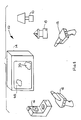
- FIG. 1 there is shown a perspective view of the various elements of the interactive game apparatus 10 of the present invention.
- the elements include photosensitive weapons 12 which are battery operated handheld devices used by the game players in conjunction with a video display such as a TV set 14 or which may be used in conjunction with each other as more fully described below.
- Additional elements of the game apparatus 10 include a photosensitive light source 16 and a rotating mirror 18 which is used in conjunction with a conventional light source such as table lamp 20.
- FIG. 2 is a cutaway view of the weapon 12 showing the location of the various internal components.
- the weapon 12 is formed of a plastic housing 22 which may be molded in the shape of a space vehicle or other attractive shape, and includes a hand grip 24 supporting a trigger 26.
- the hollow handgrip 24 also serves as a battery compartment to house batteries 30 which are used to supply power to some of the high power consumption output devices provided as part of the weapon 12. Above the handgrip 24 is a second battery compartment housing another battery 32 used to provide power to the various electronic circuits within the weapon 12.
- a visible LED 34 which is used to inform the player when the weapon is in a position to score a point against an opponent.
- a power switch 36 used to energize the weapon 12 and to select one of two operating modes. These modes include a TV mode where the opponent appears as part of the video display on the television 14, and a combat mode where the opponent is a second player who also has a weapon 12.
- a count switch 38 is mounted below the switch 36. When this switch is pressed, the LED 34 displays the player's score by flashing once for each score point.
- a printed circuit board 40 which is used to hold the various electronic components of the weapon 12 and also mounts a speaker 42 used to provide a variety of audible signals, including the player's score, to the player during the play of the game.
- a motor 44 Attached to the shaft of the motor 44 is a cam having a projection 46 thereon. Adjacent the motor 44 is a lever 48 which pivots about a hinge point 50 and is biased into position by a spring 52. A projection on the upper end of the lever 48 is used to hold in place a hinged canopy 54 and an injection seat 56. The seat 56 is biased upward by the spring 58.
- a player may insert one of a number of small figures into the ejection seat 56 by opening the canopy 54.
- the motor 44 When the motor 44 is energized, the projection 46 rotates into contact with the lever 48 causing it to release the canopy 54 and the seat 56.
- the spring 58 then causes the seat 56 and the figure sitting thereon to be ejected from the weapon 12.
- an incandescent light bulb 60 designed to project a beam of light outward toward the front of the weapon 12.
- a photosensor assembly 62 is also mounted atop the weapon 12 and is used to house a photosensor 64 which may be, for example, a cadmium sulfide cell or a silicon photodiode.
- the photosensor 64 is covered by a diffuser 66 described in more detail below.
- the photosensor 64 is used to detect light rays transmitted toward the weapon 12 in the form of a burst of coded light signals.
- the weapon 12 is used in conjunction with the TV set 14 to play the game in the TV mode in the following manner.
- the TV set 14 is tuned to a station broadcasting a program which includes portions of the video display which are coded in a unique fashion to designate a hit area 68 representing a TV opponent firing at the player operating the weapon 12 and also to designate a vulnerable score area 70 on the video screen where the player may shoot at and score aganst the TV opponent.
- the hit area 68 is designated by an area of light, the intensity of which is modulated in synchronism with the 50 HZ raster scan of the TV set 14 at a predetermined frequency.
- the frequency chosen for the hit area is 12.5 HZ (i.e. a quarter of the raster scan frequency) and the modulation is accomplished by flashing the hit area at a relatively high luminous intensity for one field of the raster scan and then blanking the hit area for the following three fields of the raster scan.
- An alternative way of creating the 12.5 HZ signal is to flash the hit area for two fields of the raster scan, and then blank the area for the following two fields.
- This modulation of the area 68 is continued for a duration of about one to two seconds to provide several cycles of the 12.5 HZ intensity modulation. This is sufficient time to permit the photosensor 64 of the weapon 12 to detect the hit area when the weapon 12 is accurately pointed at the TV set 14.
- the score area 70 is differentiated from the hit area 68 by modulating it at a different frequency.
- the score area 70 is modulated at a 25 HZ rate (i.e. one half of the raster scan frequency), accomplished by flashing the area 70 at a relatively high luminous intensity for one field of the raster scan and then blanking the area for the subsequent field of the raster scan. This pattern is also repeated for about one to two second to provide several cycles of the 25 HZ intensity modulated signal so that the photosensor 64 can sense the score area 70 when the weapon 12 is accurately aimed at the TV set 14.
- the low frequencies chosen for modulating the intensity of the areas 68 and 70 may produce a flickering on the screen of the TV set 14.
- the areas 68 and 70 are usually representing laser weapon blasts, rocket exhausts, and other such action where flicker is not objectionable and in fact enhances the realism of the scene being depicted.
- the construction of the photosensor housing 62 in combination with the diffuser 66 provides a relatively narrow field of view for detecting the modulated light signals from the TV set 14.
- the typical size for the areas 68 and 70 is 40mm x 40mm square.
- the sensitivity of the photosensor 64 is sufficient to detect the modulated light signal in a range up to 10 feet from the set 14 when the weapon 12 is pointed within two degrees of axial alignment with the particular areas 68 and 70.
- Game play is initiated when the specially coded TV program is tuned in on the set 14 and the player energizes the weapon 12 by placing the power switch 36 in the TV position.
- the TV program may also be provided using a videotape and a video recorder in conjunction with the set 14.
- an electronic processor within the weapon 12 sets an initial score for the player of 5 points. This score may be verified by pressing the switch 38.
- the speaker 42 will beep five times.
- the player points the weapon 12 at the screen in hopes of scoring against the opponents being displayed. If the weapon 12 is pointed at a hit area 68, the modulated light signal from the area 68 is detected by the photosensor 64 and the electronics within the weapon 12 records a hit against the player by generating a hit sound through the speaker 42 and by decrementing the score counter by one point.
- the player may score against the TV opponent by aiming the weapon 12 at a score area 70.
- the player is notified that he is on target to score by the illumination of the LED 34 for a short while (approximately 0.2 seconds for example).
- the player In order to score against the TV opponent, the player must depress the trigger 26 during the time the LED 34 is lit. If this is accomplished, a score sound is generated from the speaker 42, and the score counter registers an increase of one point.
- the player may check his score by pressing the switch 38 and counting the number of beeps from the speaker 42.
- the electronics within the weapon 12 energizes the motor 44 which causes the canopy 54 to open and the figure sitting in the ejection seat 56 to be ejected from the weapon 12. This ends the game for that particular player.
- the unique operation of the weapon 12 permits two-way interaction between the player and the video display. He may be hit by the video opponent and he may score against the video opponent. Additionally, several players, each armed with a weapon 12, may participate during the broadcast of the TV program to increase the excitement of the game play.
- the weapon 12 has an additional feature to permit its use with a second player having a weapon 12 without the need for a video display. This is accomplished in the following manner.
- each player sets the power switch on his respective weapon 12 to the combat position.
- the incandescent light bulb 60 is flashed at a 12.5 HZ rate to simulate the modulated light signal normally broadcast from the video screen as a hit area 68.
- One advantage of the 12.5 HZ frequency is that it is sufficiently low to enable the filament of an incandescent bulb to respond.
- the players may score against each other by aiming their weapons and pressing the trigger 26 at an appropriate time.
- the lamp 60 is flashed for at least two seconds at the 12.5 HZ rate to allow sufficient time for the filament within the lamp to warm up to full intensity.
- the weapon 12 also generates a fire sound from the speaker 42.
- the circuitry within the weapon 12 which responds to hits is disabled.
- the canopy 54 opens and ejection seat 56 ejects the toy figure.
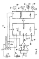
- FIG. 3 is an illustration partially in schematic and partially in block diagram form of circuitry which may be utilized in the construction of the weapon 12.
- the circuitry includes a microprocessor 72 which may be, for example, an NEC type 7507 single chip microcontroller. Output signals from the processor 72 are provided to high power drivers 74 which in turn provide power from the batteries 30 and 32 to the various output devices, namely the LED 34, the speaker 42, the incandescent light bulb 60, and the motor 44.
- the power switch 36 is a three-position slide switch having an off, a TV, and a combat position. In both the TV and combat positions, power is supplied from the batteries 30 and 32 to power the processor 72, the output devices, and amplifier and wave shaper electronics 76 used to amplify and condition the signals received from the photosensor 64.
- An output signal from the electronics 76 is provided to input terminal A2 of the processor 72.
- a trigger signal from the switch 28 is provided as an input signal at terminal A3 of the processor 72.
- a signal from the count switch 38 is provided as an input signal to the terminal A4 of the processor 72.
- the switch 36 also serves to provide a signal either to the input terminal A1 or the input terminal A0 of the processor 72 to designate whether the TV or combat mode of operation has been selected.
- a microprocessor includes all of the input, output, memory, logic, and control circuitry necessary to perform functions similar to a digital computer in miniature form.
- the processor 72 serves to perform all of the logic functions necessary for the operation of the weapon 12, including the score keeping function.
- a numeric display such as an LED or a liquid crystal display may also be used to indicate the score to the user.
- the source 16 includes a plastic molded housing 78 which supports an incandescent light source 80 mounted to radiate light in a horizontal direction.
- the source 80 is mounted within several transparent plastic rings 81 which become illuminated when the source 80 is lit and act to broaden the beam of light transmitted by the source 80.
- the housing 78 also mounts a photosensor 82 located behind a diffuser 84. Also mounted within the housing 78 is a speaker 86 for generating various sounds and a power switch 88 for applying power to the source 16 from batteries (not shown) located within the housing 78.
- the operation of the photosensitive light source 16 is as follows. During the play of the game 10, the source 16 is positioned to receive light both from the TV set 14 and the weapons 12, as shown in Figure 1.
- the photosensor 82 is capable of detecting, over a relatively wide field of view, the 12.5 HZ hit signals generated either from the hit area 68 of the video screen or from the incandescent lamps 60 in the weapons 12 when they are set in the combat mode.
- the photosensor is set to detect 12.5 HZ hit signals.
- the incandescent bulb 80 is energized in a particular fashion.
- the incandescent source 80 is modulated at 12.5 HZ rate for a 15 second interval, thus providing hit signals which radiate over a wide angle as a result of the rings 81.
- the source 16 At the completion of the 15 second interval, the source 16 generates a 25 HZ light signal for 15 seconds.
- the source 16 upon receipt of a hit signal, regenerates a hit signal followed by a score signal. It will be apparent that the source 16 becomes an additional opponent which may score against the players and upon which the players may score.
- the speaker 86 emits tones of different frequencies during the transmission of the 12.5 HZ snd 25 HZ light burst so that the players may distinguish which signals are being transmitted.
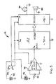
- FIG. 5 is an illustration partially in schematic and partially in block diagram form of circuitry which may be utilized in constructing the photosensitive light source 16.
- the circuitry includes a microprocessor 90 which may be similar to the microprocessor 72 used in the weapon 12. Output signals from the processor 90 are provided to drivers 92 which provide power from batteries 94 and 96 to the output devices which are the incandescent lamp 80 and the speaker 86.
- the power switch 88 provides power from the batteries 94 and 96 to the processor 90, the drivers 92, and amplifier and wave shaper electronics 98 which amplify and condition the signal from the photosensor 82.
- An output signal from the electronics 98 is provided to input terminal A0 of the processor 90, which performs all of the logic and timing functions necessary for the operation of the photosensitive light source 16.
- the rotating mirror 18 shown in detail in Figures 6 and 7.
- the mirror 18 consists of a plastic base 100 containing batteries and a motor used to rotate a conical reflector 102 about a vertical axis. As shown in the top view of Figure 7, the reflector 102 has half of its surface covered with a reflective material while the other half of the surface is coated black.
- a power switch 88 and speed control 104 is provided to adjust the speed of rotation of the reflector 102.
- the rotating mirror 18 is used in conjunction with a light source such as a table lamp 20 to reflect light from that light source into the play area. By the proper setting of the speed control 104, the reflector 102 may be caused to rotate at either a 12.5 HZ or a 25 HZ rate, thereby producing either the hit signal or the score signal from the light produced by the lamp 20.
- a convenient way to set the rotation speed of the reflector to 12.5 HZ is to aim a weapon 12 at the mirror 18 and adjust the speed control 104 until the weapon 12 registers a hit.
- the weapon 12 may also be used to assist in adjusting the speed of the reflector 102 to 25 HZ by pointing the weapon 12 at the reflector 102 and adjusting the control 104 until the target LED 34 switches on, indicating that a score has been detected.
- a flat mirror may also be used in conjunction with one of the weapons 12. By properly aiming the weapon 12 at the mirror and pressing the trigger in the combat mode, the 12.5 HZ hit signal will be reflected from the mirror back to the weapon, which may then register a hit.
- Figure 8 is a cross-sectional view of the photosensor assembly 62 used in the weapon 12. It is also indicative of the photosensor assembly used in the light source 16.
- the assembly includes a housing which mounts the photosensor 64.
- the housing is closed by a diffuser 66.
- the diffuser 66 is generally hemispherical in shape and has a central circular aperture 106 which is aligned with the optical axis of the photosensor 64.
- the aperture 106 provides a direct path to the photosensor 64 for the low intensity light signals from the TV set 14 when these light signals are aligned within a few degrees of the axis of the sensor 64 without suffering from the attenuating effects of the diffuser 66.
- the diffuser 66 permits wide angle reception of the higher intensity incandescent light signals generated by other weapons 12 or the accessories 16 and 18.
- the construction of the assembly 62 is substantially identical in the photosensitive light source 16 except for the shape of the aperture 106.
- the diffuser 84 contains an oblong aperture 108 as shown in Figure 10 as opposed to the circular aperture 106 used for the diffuser 66 in the weapon 12.
- the larger aperture 108 provides a larger field of view for the source 16 when responding to signals from the TV set 14.
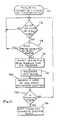
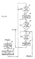
- Figure 11 is a flow chart describing the operation of the microprocessor 72 in the weapon 12 when that weapon is responsive to hit from an opponent in the form of a burst of light whose intensity is modulated at 12.5 HZ.
- the routine described by the flow chart in Figure 11 is entered at step 110 when the power switch is moved to either the combat or TV mode of operation.
- the score counter within the processor 72 is initialized to five points.
- step 110 The program moves from step 110 to step 112 where the processor 72 determined whether at least two cycles of the 12.5 HZ light signal have been detected by the photosensor 64. If such detection has not taken place, the processor 72 continues monitoring the photosensor 64 until a hit is detected. At that point, the program moves to step 114 to determine if the 12.5 HZ sensing for this weapon has been inhibited by the score routine to be described below. If the sensing is inhibited, the program returns to step 112 and continues monitoring the sensor 64 for future hit detection.
- step 116 both 12.5 HZ and 25 HZ sensing is inhibited for 0.3 seconds. In other words, the weapon 12 will not respond to any additional 12.5 HZ or 25 HZ light signals for 0.3 seconds.
- step 118 a hit sound is generated in the speaker 42.
- step 120 a one point loss is recorded by decrementing the counter previously set to 5 points.
- step 122 determines if the counter is at zero. If it is not, the program returns to step 112 to monitor the sensor 64. If the counter is at zero, the program moves from step 122 to 124 and energizes the motor 44 to cause the figure, canopy, and ejection seat to eject from the weapon 12. At the same time, an explosion sound is generated by the speaker 42.
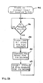
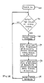
- Figures 12A and 12B are flow charts showing the operation of the processor 72 when the weapon 12 is in the TV mode and the sensor 64 is responsive to a score signal in the form of a 25 HZ burst of light.
- the program is entered when the power switch is turned on to the TV mode, at which time the score counter is initialized to 5 points.
- the program moves from step 126 to step 128 to determine whether two cycles of the 25 HZ light signal have been detected. If not, the program cycles back to step 128 and continues to monitor the photosensor 64.
- step 130 it is determined whether 25 HZ sensing has been previously inhibited by the hit routine described with respect to Figure 11. If 25 HZ sensing has been inhibited, the program returns to step 128 continues to monitor the sensor 64 for subsequent 25 HZ light signal reception.
- step 130 the program moves from step 130 to step 132.
- step 132 the LED 34 is illuminated for 0.2 seconds and a 0.85 second timer is started.
- the illumination of the LED 34 is a signal to the player that he must press the trigger before the LED extinguishes in order to score a hit against the opponent.
- step 134 the program moves from step 132 to step 134 where 12.5 HZ and 25 HZ sensing is inhibited, thus preventing the weapon 12 from responding to subsequent light signals.
- step 136 determines if the trigger 26 has been pulled. If the trigger has not been pulled, the program moves to step 138 to determine whether the target light 34 has been turned off. If it has not, the program recycles to step 136 to monitor the status of the trigger. If the LED 34 is extinguished, the program moves from step 138 to step 143 where 12.5 HZ and 25 HZ sensing is reenabled. The program then moves back to step 128 to monitor the sensor 64 for future detection of light signals.
- step 136 if the trigger has been pulled by the player, the program moves to step 137 to determine whether the LED 34 is still illuminated. If the LED is still illuminated, the program moves to step 140 ( Figure 128) to generate a score sound in the speaker 42 and to start a one second timer. The program then moves to step 142 to record a gain of one point by incrementing the score counter.
- step 144 determines whether the 0.85 second timer has elapsed. If it has not, the program recycles at step 144 to reinterrogate the timer until it does elapse. At that time, the program moves to step 146 to reenable the sensing of 12.5 HZ light signals and then moves to step 14 to determine whether the one second timer has elapsed. If it has not, the program reinterrogates the timer until it does elapse. At that time, the program moves to step 150 to see if the trigger is still being pulled. If it is, the program recycles at step 150 and continues to interrogate the signal from the trigger switch 28 until the trigger is released. At that time, the program moves to step 152 and enables the sensing of 25 HZ light signals. The program then returns to step 128 to monitor the future reception of coded light signals by the sensor 64.
- step 137 if the program determines at step 136 that the trigger has been pulled but the target LED is not on, thereby indicating that the player was not fast enough to record a score against the opponent, the program moves from step 137 to step 139.
- step 139 a fire sound is generated by the speaker 42 for 0.38 seconds.
- the 12.5 HZ sensing is reenabled.
- the program then moves to step 150 to determine if the trigger is still being pulled, and cycles at that step until the trigger is released. When the trigger is released, the program moves to step 152 to enable the 25 HZ sensing and then returns to step 128 to monitor the sensor 64 for subsequent reception of coded light signals.
- logic is included in the processor 72 to reenable the detection of 12.5HZ sensing before the LED target light is extinguished and before the player has had a chance to release the trigger. This feature increases the excitement of the game since a player may be hit even while he is recording a score against the opponent. At the same time, the logic precludes the player from recording a second score against the opponent until he has released the trigger.
- Figure 13 is a flow chart depicting the operation of the processor 72 when the weapon 12 is in the combat mode and is firing against the opponent.
- the program is entered at step 154 with the power switch set to the combat mode which initiates the score counter to five points.
- the program then moves to step 156 where it is determined whether the trigger is being pulled. If it is not, the program recycles at step 156 to continue interrogating the trigger signal.
- step 150 the incandescent light bulb 60 is flashed at a 12.5 HZ rate for two seconds.
- a fire sound is generated at step 160 for 0.4 seconds and at step 162 both 12.5 HZ and sensing are inhibited for 0.4 seconds.
- the program then returns to step 156 to monitor the status of the trigger for subsequent firing.
- Figure 14 is a flow chart depicting the operation of the microprocessor 90 in the photosensitive light source 16.
- the program is entered at step 164 when power is turned on by switch 88.
- the program then moves to step 166 to detect whether at least two cycles of the 12.5 HZ hit signal have been detected. If not, the program recycles at step 166 and monitors the sensor 82 until a hit detection is sensed. Upon that occurrence, the program moves to step 168 where further 12.5 HZ sensing is inhibited.
- step 170 the incandescent lamp 80 is pulsed at 12.5 HZ rate for 15 seconds.
- a sound is generated by speaker 86 indicating that the 12.5 HZ hit signal is active.
- step 172 the incandescent lamp 80 is pulsed at a 25 HZ rate for a period of 15 seconds and a different sound is generated by the speaker 86 to indicate that the 25 HZ score signal is active.
- step 174 12.5 HZ sensing is reenabled and then the program returns to step 166 to monitor the sensor 82 for subsequent detection of 12.5 HZ signals.
- the apparatus 10 is by no means limited to these game play options, and additional modes of operation are limited only by the imagination of the players. For example, while two players may have their weapons in the TV mode and may be interacting with the video display on the TV set 14, one of the players may switch his weapon to the combat mode and turn upon the other player in an effort to decrease the other player's score. Similarly, either player may switch to the combat mode and fire upon the photosensitive light source 16 causing it to generate both hit and score signals.
- the novel game play apparatus of the present invention provides a versatile and exciting combination of game play options which permit interaction of one or more players with a video presentation, permits interaction between two or more players, and permits a player to play by himself with or without a video display.
Landscapes
- Engineering & Computer Science (AREA)
- Multimedia (AREA)
- Human Computer Interaction (AREA)
- Theoretical Computer Science (AREA)
- Toys (AREA)
- Aiming, Guidance, Guns With A Light Source, Armor, Camouflage, And Targets (AREA)
Applications Claiming Priority (2)
| Application Number | Priority Date | Filing Date | Title |
|---|---|---|---|
| US274 | 1986-12-30 | ||
| US07/000,274 US4844475A (en) | 1986-12-30 | 1986-12-30 | Electronic interactive game apparatus in which an electronic station responds to play of a human |
Publications (2)
| Publication Number | Publication Date |
|---|---|
| EP0273543A2 true EP0273543A2 (de) | 1988-07-06 |
| EP0273543A3 EP0273543A3 (en) | 1990-04-04 |
Family
ID=21690758
Family Applications (1)
| Application Number | Title | Priority Date | Filing Date |
|---|---|---|---|
| EP87307117A Withdrawn EP0273543A3 (en) | 1986-12-30 | 1987-08-11 | Interactive game apparatus |
Country Status (5)
| Country | Link |
|---|---|
| US (1) | US4844475A (de) |
| EP (1) | EP0273543A3 (de) |
| JP (1) | JPS63288182A (de) |
| AU (1) | AU579523B2 (de) |
| BR (1) | BR8704983A (de) |
Families Citing this family (33)
| Publication number | Priority date | Publication date | Assignee | Title |
|---|---|---|---|---|
| US5213337A (en) * | 1988-07-06 | 1993-05-25 | Robert Sherman | System for communication using a broadcast audio signal |
| US5098110A (en) * | 1989-07-19 | 1992-03-24 | Michael Yang | Method for remotely controlling a video game system of a video game apparatus |
| EP0500794A4 (en) * | 1989-11-22 | 1993-02-03 | David C. Russell | Computer control system |
| JP3153603B2 (ja) * | 1991-12-28 | 2001-04-09 | 任天堂株式会社 | 射撃ゲームシステムに用いられる銃装置 |
| US5351969A (en) * | 1992-05-26 | 1994-10-04 | Smith Engineering | Remote control system for raster scanned video display |
| US5465982A (en) * | 1993-12-14 | 1995-11-14 | Resrev Partners | Method and apparatus for disclosing a target pattern for identification |
| US5796387A (en) * | 1994-08-16 | 1998-08-18 | Smith Engineering | Positioning system using infrared radiation |
| US5832296A (en) * | 1995-04-26 | 1998-11-03 | Interval Research Corp. | Wearable context sensitive user interface for interacting with plurality of electronic devices of interest to the user |
| US5672108A (en) * | 1996-01-16 | 1997-09-30 | Tiger Electronics, Inc. | Electronic game with separate emitter |
| US6302796B1 (en) | 1997-02-05 | 2001-10-16 | Toymax Inc. | Player programmable, interactive toy for a shooting game |
| US5984788A (en) * | 1997-06-09 | 1999-11-16 | Toymax Inc. | Interactive toy shooting game having a target with a feelable output |
| US5904621A (en) * | 1997-06-25 | 1999-05-18 | Tiger Electronics, Ltd. | Electronic game with infrared emitter and sensor |
| US6261180B1 (en) | 1998-02-06 | 2001-07-17 | Toymax Inc. | Computer programmable interactive toy for a shooting game |
| JP3470071B2 (ja) | 1999-10-04 | 2003-11-25 | 新世代株式会社 | 釣りゲーム装置 |
| JP2002007072A (ja) * | 2000-06-27 | 2002-01-11 | Namco Ltd | 位置指示装置及び情報記憶媒体 |
| US6814667B2 (en) | 2001-07-27 | 2004-11-09 | Robert W. Jeffway, Jr. | eTroops infrared shooting game |
| JP3803589B2 (ja) * | 2002-02-15 | 2006-08-02 | Necパーソナルプロダクツ株式会社 | 射撃訓練システムおよび方法 |
| US20030199324A1 (en) * | 2002-04-23 | 2003-10-23 | Xiaoling Wang | Apparatus and a method for more realistic shooting video games on computers or similar devices using visible or invisible light |
| US20040002369A1 (en) * | 2002-05-06 | 2004-01-01 | Walker Jay S. | Method and apparatus for modifying a game based on results of game plays |
| US20040087378A1 (en) * | 2002-11-01 | 2004-05-06 | Poe Lang Enterprise Co., Ltd. | Shooting exercise for simultaneous multiple shooters |
| US7618323B2 (en) * | 2003-02-26 | 2009-11-17 | Wms Gaming Inc. | Gaming machine system having a gesture-sensing mechanism |
| US7846028B2 (en) * | 2005-05-19 | 2010-12-07 | Shoot The Moon Products Ii, Llc | Lazer tag advanced |
| US20060287114A1 (en) * | 2005-06-03 | 2006-12-21 | Binh Luong | Electronic tag game |
| US7209577B2 (en) * | 2005-07-14 | 2007-04-24 | Logitech Europe S.A. | Facial feature-localized and global real-time video morphing |
| US20070230794A1 (en) * | 2006-04-04 | 2007-10-04 | Logitech Europe S.A. | Real-time automatic facial feature replacement |
| WO2007127258A2 (en) * | 2006-04-27 | 2007-11-08 | Wms Gaming Inc. | Wagering game with multi-point gesture sensing device |
| CN201436044U (zh) * | 2006-05-04 | 2010-04-07 | 马特尔公司 | 可佩戴装置 |
| US8721460B2 (en) * | 2007-01-04 | 2014-05-13 | Jakks Pacific, Inc. | Toy laser gun and laser target system |
| US8959459B2 (en) | 2011-06-15 | 2015-02-17 | Wms Gaming Inc. | Gesture sensing enhancement system for a wagering game |
| US9086732B2 (en) | 2012-05-03 | 2015-07-21 | Wms Gaming Inc. | Gesture fusion |
| GB201713651D0 (en) * | 2017-08-24 | 2017-10-11 | Fureal Ltd | Play Apparatus |
| US10661173B2 (en) | 2018-06-26 | 2020-05-26 | Sony Interactive Entertainment Inc. | Systems and methods to provide audible output based on section of content being presented |
| US11123647B2 (en) * | 2019-02-04 | 2021-09-21 | Disney Enterprises, Inc. | Entertainment system including performative figurines |
Family Cites Families (14)
| Publication number | Priority date | Publication date | Assignee | Title |
|---|---|---|---|---|
| US2516319A (en) * | 1941-02-12 | 1950-07-25 | Raymond T Moloney | Photoelectric marksmanship device |
| US2957693A (en) * | 1956-12-03 | 1960-10-25 | Arthur C Ross | Electrical robot dueler |
| AU5470873A (en) * | 1972-05-18 | 1974-10-24 | Skb Arms Co | Shooting games |
| DE2653093B1 (de) * | 1976-11-23 | 1977-09-29 | Loewe Opta Gmbh | Fernsehspielschaltung mit einem zielflecksuchgeraet |
| US4123164A (en) * | 1977-01-03 | 1978-10-31 | The Singer Company | Autocollimating assembly for the self-calibration of a stellar navigational system |
| US4306769A (en) * | 1980-04-09 | 1981-12-22 | Martinet Michael E | Interior illumination apparatus using sunlight |
| GB2095377A (en) * | 1981-03-11 | 1982-09-29 | Hawes Alan | Electronic shooting game |
| US4602907A (en) * | 1981-08-17 | 1986-07-29 | Foster Richard W | Light pen controlled interactive video system |
| GB2126460A (en) * | 1982-07-12 | 1984-03-21 | Peter Kurt Shreck | Video response testing apparatus |
| US4545583A (en) * | 1982-12-23 | 1985-10-08 | Showdown Electronics, Inc. | Electronic gun and target apparatus and method |
| US4533144A (en) * | 1983-07-11 | 1985-08-06 | Manuel Juarez | Electronic game |
| US4695953A (en) * | 1983-08-25 | 1987-09-22 | Blair Preston E | TV animation interactively controlled by the viewer |
| JPS61156405A (ja) * | 1984-12-28 | 1986-07-16 | Nintendo Co Ltd | 光感応制御装置 |
| US4654700A (en) * | 1985-04-01 | 1987-03-31 | Sanders Associates, Inc. | Optical decoder |
-
1986
- 1986-12-30 US US07/000,274 patent/US4844475A/en not_active Expired - Lifetime
-
1987
- 1987-07-23 AU AU76122/87A patent/AU579523B2/en not_active Ceased
- 1987-08-11 EP EP87307117A patent/EP0273543A3/en not_active Withdrawn
- 1987-09-28 BR BR8704983A patent/BR8704983A/pt unknown
- 1987-12-02 JP JP62303465A patent/JPS63288182A/ja active Pending
Also Published As
| Publication number | Publication date |
|---|---|
| BR8704983A (pt) | 1988-07-19 |
| AU579523B2 (en) | 1988-11-24 |
| JPS63288182A (ja) | 1988-11-25 |
| EP0273543A3 (en) | 1990-04-04 |
| US4844475A (en) | 1989-07-04 |
| AU7612287A (en) | 1988-06-23 |
Similar Documents
| Publication | Publication Date | Title |
|---|---|---|
| US4844475A (en) | Electronic interactive game apparatus in which an electronic station responds to play of a human | |
| US6302796B1 (en) | Player programmable, interactive toy for a shooting game | |
| US4266776A (en) | Multi target-shooter game apparatus | |
| US5437463A (en) | Target game apparatus | |
| US5672108A (en) | Electronic game with separate emitter | |
| US6071166A (en) | Light shooting and detecting toy figures | |
| US6328651B1 (en) | Projected image target shooting toy | |
| US4363484A (en) | Electronic table tennis game apparatus | |
| US7244183B1 (en) | Gaming system employing both action figure and video game play | |
| US6293869B1 (en) | Shooting game target with graphic image display device | |
| US5577962A (en) | Virtual bullet charging device for gun game machine | |
| US7632187B1 (en) | Device and method for an electronic tag game | |
| US3960380A (en) | Light ray gun and target changing projectors | |
| US4802675A (en) | Toy gun | |
| US4772028A (en) | Electronic shootout game | |
| US5375847A (en) | Toy assembly | |
| US20020022519A1 (en) | Video game control adapter apparatus | |
| US6248019B1 (en) | Amusement apparatus for a shooting game with successive potential scoring emissions | |
| US6007429A (en) | Electronic target game apparatus and method | |
| JP2006212224A (ja) | ダーツ及びダーツゲーム装置 | |
| US4799687A (en) | Projected image tag game | |
| GB2290483A (en) | Simulated weapon | |
| US20050043102A1 (en) | Electronic miniature tag game | |
| JPS62210396A (ja) | 標的ゲ−ム | |
| JPS63194198A (ja) | 射撃遊戯具における被弾検知機構 |
Legal Events
| Date | Code | Title | Description |
|---|---|---|---|
| PUAI | Public reference made under article 153(3) epc to a published international application that has entered the european phase |
Free format text: ORIGINAL CODE: 0009012 |
|
| AK | Designated contracting states |
Kind code of ref document: A2 Designated state(s): BE DE ES FR GB IT LU NL |
|
| PUAL | Search report despatched |
Free format text: ORIGINAL CODE: 0009013 |
|
| AK | Designated contracting states |
Kind code of ref document: A3 Designated state(s): BE DE ES FR GB IT LU NL |
|
| STAA | Information on the status of an ep patent application or granted ep patent |
Free format text: STATUS: THE APPLICATION IS DEEMED TO BE WITHDRAWN |
|
| 18D | Application deemed to be withdrawn |
Effective date: 19901005 |
|
| RIN1 | Information on inventor provided before grant (corrected) |
Inventor name: LAM, PETER AR-FU Inventor name: BRO, JAY MERVIN Inventor name: ROSENTHAL, JANICE ELAINE Inventor name: SAFFER, GARY MICHAEL Inventor name: HALFORD, WAYNE RAY Inventor name: HILL, PETER COLLIER Inventor name: NAGHSHINEH, SHAHRAM Inventor name: BODEN, SCOTT THOMAS Inventor name: WILLIAMS, PAUL ALEXANDER Inventor name: CORSIGLIA, JEFFREY J. |