EP0273563B1 - Loquet de verrouillage du couvercle d'un ventilateur - Google Patents
Loquet de verrouillage du couvercle d'un ventilateur Download PDFInfo
- Publication number
- EP0273563B1 EP0273563B1 EP87310033A EP87310033A EP0273563B1 EP 0273563 B1 EP0273563 B1 EP 0273563B1 EP 87310033 A EP87310033 A EP 87310033A EP 87310033 A EP87310033 A EP 87310033A EP 0273563 B1 EP0273563 B1 EP 0273563B1
- Authority
- EP
- European Patent Office
- Prior art keywords
- fan
- catch
- shutter plate
- ventilator
- detents
- Prior art date
- Legal status (The legal status is an assumption and is not a legal conclusion. Google has not performed a legal analysis and makes no representation as to the accuracy of the status listed.)
- Expired - Lifetime
Links
- 238000000605 extraction Methods 0.000 claims abstract description 14
- 230000005484 gravity Effects 0.000 claims description 3
- 230000006835 compression Effects 0.000 claims description 2
- 238000007906 compression Methods 0.000 claims description 2
- 230000000694 effects Effects 0.000 abstract description 3
- XLYOFNOQVPJJNP-UHFFFAOYSA-N water Substances O XLYOFNOQVPJJNP-UHFFFAOYSA-N 0.000 description 4
- 238000007599 discharging Methods 0.000 description 3
- 238000003466 welding Methods 0.000 description 3
- 239000000463 material Substances 0.000 description 2
- 238000000034 method Methods 0.000 description 2
- 230000015572 biosynthetic process Effects 0.000 description 1
- 238000007664 blowing Methods 0.000 description 1
- 238000005266 casting Methods 0.000 description 1
- 238000010276 construction Methods 0.000 description 1
- 238000000465 moulding Methods 0.000 description 1
- 238000009423 ventilation Methods 0.000 description 1
Images


Classifications
-
- F—MECHANICAL ENGINEERING; LIGHTING; HEATING; WEAPONS; BLASTING
- F04—POSITIVE - DISPLACEMENT MACHINES FOR LIQUIDS; PUMPS FOR LIQUIDS OR ELASTIC FLUIDS
- F04D—NON-POSITIVE-DISPLACEMENT PUMPS
- F04D25/00—Pumping installations or systems
- F04D25/02—Units comprising pumps and their driving means
- F04D25/08—Units comprising pumps and their driving means the working fluid being air, e.g. for ventilation
- F04D25/12—Units comprising pumps and their driving means the working fluid being air, e.g. for ventilation the unit being adapted for mounting in apertures
- F04D25/14—Units comprising pumps and their driving means the working fluid being air, e.g. for ventilation the unit being adapted for mounting in apertures and having shutters, e.g. automatically closed when not in use
-
- F—MECHANICAL ENGINEERING; LIGHTING; HEATING; WEAPONS; BLASTING
- F16—ENGINEERING ELEMENTS AND UNITS; GENERAL MEASURES FOR PRODUCING AND MAINTAINING EFFECTIVE FUNCTIONING OF MACHINES OR INSTALLATIONS; THERMAL INSULATION IN GENERAL
- F16K—VALVES; TAPS; COCKS; ACTUATING-FLOATS; DEVICES FOR VENTING OR AERATING
- F16K17/00—Safety valves; Equalising valves, e.g. pressure relief valves
- F16K17/02—Safety valves; Equalising valves, e.g. pressure relief valves opening on surplus pressure on one side; closing on insufficient pressure on one side
- F16K17/04—Safety valves; Equalising valves, e.g. pressure relief valves opening on surplus pressure on one side; closing on insufficient pressure on one side spring-loaded
- F16K17/042—Safety valves; Equalising valves, e.g. pressure relief valves opening on surplus pressure on one side; closing on insufficient pressure on one side spring-loaded with locking or disconnecting arrangements
Definitions
- the present invention relates to ventilators and is concerned with powered, direct discharge ventilators, that is to say, ventilators which do not have a weathering cowl.
- a self-weathering, non-return shutter means is employed to close the exit from the extraction fan duct of the ventilator when the ventilator fan is not operating and thereby prevent weather entry through the ventilator and draught entering the building, as well as conserving the heat in the building.
- the non-return shutter means in known ventilators of the kind described above takes various forms but essentially, it is automatic in the sense that it is opened by the forced draught of the extraction fan and closed under the action of gravity, possibly assisted by spring action, when the extraction fan is stopped.
- a conventional windshield hitherto provided has necessarily been somewhat tall. This is, in itself, open to objection for aesthetic reasons insofar as a roof mounted ventilator is, preferably of low height so as not to stand out against the sky. Also, the higher the windshield the higher is the "wind-over" suction effect.
- a non-return shutter means in the form of a flat disc or plate hinged or guided to float up on the airstream when the fan is started whilst maintaining a position generally parallel to that which it occupies in its fan duct closing position.
- the object of the present invention is to provide a simple and therefore reliable locking and unlocking arrangement for the shutter plate in its closed Position, which will automatically unlock the plate when the fan motor is started and which will automatically lock the plate when the fan motor is shut down and the shutter plate returns to its closed position.
- a powered, direct discharge ventilator comprising an extraction fan having a fan duct and a self weathering, non-return shutter plate for closing the exit from the extraction fan duct when the ventilator fan is not operating, the non-return shutter plate being arranged to be opened by the airstream when the fan is started whilst maintaining a position generally parallel to that which it occupies in its fan duct closing position and to be closed under the action of gravity and/or by spring action when the fan is stopped, wherein the fan mounts a centrifugally operable latch means coincident with the rotational axis of the fan for opening and closing the shutter plate.
- the detents are pivoted for radially inward and radially outward swinging movement.
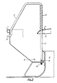
- the ventilator there shown is assumed to be mounted on a flat roof with the axis C of rotation of its extraction fan K extending vertically.
- the ventilator comprises a base B having a square base flange 10 intended to be attached to the roof and a circular upstanding wall 11 defining a ventilation opening or throat 12 forming an extraction fan duct having a bell mouthed entry portion 13.
- Carried from the base flange 10 by brackets F is a shallow, inverted, frusto-conical dish form member D having a central, circular opening 15 in its floor.
- An upper edge portion of the wall 11 is received through the opening 15 with a small clearance sealed by an elastomeric seal S which acts also as a draught seal for the non-return shutter yet to be described.
- the wall 11 penetrates upwardly into the dish-form member D to form a rain water collection channel 16 from which rain water is drained through holes 16' onto the outside of the roof.
- the upwardly discharging stream of air generated through the duct 12 of the ventilator prevents the entry of rain into the duct 12 of the ventilator and therefore into the building.
- a self weathering non-return shutter P is provided to close the exit from the extraction fan duct 12.
- the non-return shutter P is of circular outline and is formed by a single disc or plate of shallow inverted-dish construction which rests on a draught seal portion of the seal S surrounding the upper edge portion of the wall 11 such that the non-return shutter P is closely spaced above the top edge of the wall 11 and covers over and closes the opening defined by the wall 11 when the non-return shutter P is in its closed position.
- the non-return shutter P shelters the extraction fan duct 12 from the entry of rain and snow and the slope of the upper surface of the non-return shutter P drains rain water over the upper edge of the wall 11 into the rain water collection channel 16 from where it drains onto the outside of the roof through the holes 16'.
- a wire bird-guard or grid G is mounted on top of the member D.
- the grid is composed of an array of horizontally disposed circular wire hoops 14 of progressively smaller diameter held in vertically spaced apart relationship with respect to one another by upwardly extending interconnecting spring wires 17 having cranked lower end portions 17' sprung through individual holes in the wall of the dish-form member D and upper end portions which extend first inwardly over the dish form member D and then vertically downwardly to connect by means of screw threaded connections 18, 20 with the floor of the member D.
- the member D acts as a windshield to shelter the non-return shutter P against the action of wind to some extent when the non-return shutter is closed, the member D being nevertheless of an acceptably low height to meet aesthetic requirements.
- the member D by itself is not capable of preventing unwanted opening of the non-return shutter P under all wind conditions.
- the fan K mounts a centrifugally operable latch means 30 coincident with the rotational axis C of the fan and the non-return shutter P carries a catch 31 positioned to be engaged by the latch means 30 when the non-return shutter P is in its closed position, the latch means 30 engaging the catch 31 to lock the non-return shutter P closed when the fan K is stationary and being centrifugally displaceable to disengage the catch 31 when the fan is operated.
- the catch 31 is in the form of a headed pin which is fixed by a screw fastener 32 to the underside of the non-return shutter so as to extend with its shank along the axis C.
- the head 35 (see Fig. 3) of the catch pin 31 enters a centrally disposed circular hole 36 in an upper end wall of a cylindrical housing portion 37 of the latch means as the non-return shutter P is urged to its closed position upon shut-down of the fan K.
- the head 35 is in the form of a disc having a chamfered, downwardly facing edge 38 chamfered at an angle of 45°.
- the latch means 30 comprises a pair of generally rectangular shaped detents 40 pivotally mounted for radial inward and radial outward swinging movement each on a downwardly directed pivot pin 41 carried by the housing portion 37 at a position radially spaced from the axis C.
- Each pivot pin 41 is of stepped configuration with steps of reducing diameter, proceeding downwardly, the uppermost step 41 a presenting an annular, downwardly directed thrust bearing surface for the detent 40, the next step 41 b presenting an outer cylindrical pivot surface for the detent 40 and the two subsequent steps 41 c and 41 d being fitted ultrasonically welded as at 42 (see Fig.
- the detents 40 extend in opposite directions, inwardly of the housing formed by the housing and base portions 37 and 54 respectively and lie generally parallel to one another and to a diameter of the housing.
- the housing and base portions 37 and 54 of the housing are ultrasonically welded together as at 56 (see Fig. 4).
- the detents 40 are spring pressed towards the axis C by cantilevered spring arms 60 of generally L shaped springs 59 the other arms 61 of which are received in slots 62 (see Figs.
- the base portion 54 is formed with corresponding blocks 70, without slits or recesses, which blocks 70 abut the blocks 63.
- the blocks 70 have upwardly facing bearing surfaces 71 which engage the lower edges of the spring arms 60, 61 to support the springs 59.
- the detents 40 Upon start up of the fan K the detents 40 swing outwardly under the action of centrifugal force and, at a predetermined speed, the detents clear the head 35 of the catch pin 31 and the non-return shutter P is lifted by the stream of air discharging from the fan K against the action of the non-return shutter return springs 23, the non-return shutter plate sliding up the guide wire portions 21 which maintain the non-return shutter generally horizontal and parallel to its closed position.
- the detents 40 are returned to their locking positions shown in Fig. 4 by the springs 59, as the fan impeller slows.
- the action of the springs 23 is to return the non-return shutter to its closed position but the discharging air holds the non-return shutter open until the fan impeller slows almost to a standstill.
- the detents are formed with inner, upwardly facing chamfered edges 74, chamfered at 45°. These are finally engaged by the downwardly facing chamfered edge 38 of the catch pin and the catch forces the detents apart and latches into its locking position underlying the detents 40 as seen in Fig. 3.
- the springs 23 overcome the springs 59 to move the non-return shutter to its closed position and the springs 59 then return the detents to their locking position.
- the latch means as described is formed in six pieces which are readily manufactured by moulding or casting techniques and which are readily assembled in an "upside-down" position. Also, the housing portions are readily welded together at the positions specified, using an ultrasonic welding technique.
- the base portion has an upstanding wall circumferentially castellated on its outside surface to provide gaps for the ultrasonic welding material connecting the base portion 37 to the housing portion 54.
- the step 41 d of the detent pivot pins 41 provide a gap in the bores 50 for ultrasonic welding material uniting the pivot pins 41 to the base 54.
- the latch means 30 is attached to the fan by a single central attachment screw 80 (see Fig. 1) entered through a centrally disposed hole 81 in the base portion 54.
- the base portion 54 has pairs of ribs 84 (see Fig. 9) on its underside which receive between the ribs of each pair one radially directed formation of the fan impeller, the ribs 84 thus ensuring that the latch means 30 is driven in rotation with the impeller at the impeller speed.
- the latch means 30 is symmetrical about the axis of rotation C of the fan to avoid unbalancing the fan motor.
- the detents 40 may be replaced by detents which are linearly displaceable radially outwardly in the housing under the action of centrifugal forces and linearly displaceable radially inwardly under the action of restoring forces which may be gravitational forces and/or spring forces.
Landscapes
- Engineering & Computer Science (AREA)
- General Engineering & Computer Science (AREA)
- Mechanical Engineering (AREA)
- Air-Conditioning For Vehicles (AREA)
- Air-Flow Control Members (AREA)
- Structures Of Non-Positive Displacement Pumps (AREA)
- Massaging Devices (AREA)
- Extraction Or Liquid Replacement (AREA)
- Ventilation (AREA)
- Engine Equipment That Uses Special Cycles (AREA)
Claims (7)
- Dispositif de ventilation motorisé à évacuation directe, comprenant un ventilateur d'extraction (K) ayant un conduit de ventilateur (12) et une plaque (P) formant un couvercle anti-retour d'autoprotection à l'égard du temps extérieur, pour fermer l'orifice de sortie du conduit (12) du ventilateur d'extraction lorsque ce ventilateur (K) n'est pas en service, la plaque (P) formant un couvercle anti-retour étant disposée de manière à être ouverte par le courant d'air, lorsque le ventilateur (K) est mis en marche, tout en conservant une position qui est généralement parallèle à celle qu'elle occupe dans sa position de fermeture du conduit du ventilateur, et à se fermer sous l'action de la gravité et/ou d'un ressort lorsque le ventilateur (K) est arrêté, le ventilateur (K) portant un dispositif de verrouillage (30), pouvant être actionné sous l'effet de la force centrifuge, coïncidant avec l'axe de rotation (C) du ventilateur, caractérisé en ce que la plaque (P) formant couvercle anti-retour porte un organe d'arrêt (31) disposé de manière à venir en prise avec le dispositif de verrouillage (30) lorsque la plaque (P) formant couvercle anti-retour se trouve dans sa position fermée, le dispositif de verrouillage (30) étant en prise avec l'organe d'arrêt (31) de manière à verrouiller la plaque couvercle (P) en position de fermeture lorsque le ventilateur (K) est à l'arrêt et pouvant être déplacé, sous l'action de la force centrifuge, de manière à libérer l'organe d'arrêt (31) lorsque le ventilateur est mis en service.
- Dispositif de ventilation suivant la revendication 1 caractérisé en ce que la plaque (2) formant couvercle anti-retour est guidée, pendant ses mouvements d'ouverture et de fermeture, sur des tiges de guidage (21) parallèle à l'axe de rotation (C) du ventilateur et sur ces tiges de guidage (21) sont montés des ressorts de compression (23) sollicitant la plaque (P) formant couvercle anti-retour vers sa position fermée.
- Dispositif de ventilation suivant l'une quelconque des revendications 1 ou 2 caractérisé en ce que l'organe d'arrêt (31) et le dispositif de déverrouillage (30) présentent des surfaces de came (38,74) coopérant entre elles et permettant à l'organe d'arrêt (31) de déplacer le dispositif de verrouillage (30) lorsque la plaque (P) formant couvercle anti-retour est déplacée vers sa position fermée.
- Dispositif de ventilation suivant l'une quelconque des revendications précédentes caractérisé en ce que le dispositif de verrouillage (30) comprend une pluralité de cliquets (40) montés de manière à pouvoir se déplacer radialement vers l'intérieur et vers l'extérieur de l'organe d'arrêt (31), les cliquets (40) étant sollicités radialement vers l'intérieur sous l'action d'un ressort et/ou de la gravité.
- Dispositif de ventilation suivant la revendication 4 caractérisé en ce que les cliquets (40) sont montés à pivotement de manière à effectuer un mouvement de basculement radial vers l'intérieur et vers l'extérieur.
- Dispositif de ventilation suivant la revendication 5 caractérisé en ce que le dispositif de verrouillage (30) comprend un boîtier (37,54) ayant une base (54) montée sur le ventilateur (K) et un couvercle (37) porté par la base (54), le couvercle (37) ayant une paroi frontale percée d'une ouverture centrale (36) pour recevoir l'organe d'arrêt (31) à l'intérieur du boîtier (37,54), cette paroi frontale (37) portant une paire de cliquets (40) montés à pivotement sur cette paroi frontale, les cliquets (40) s'étendant dans des directions opposées, à partir de leurs pivots respectifs, vers l'intérieur du boîtier (37,54) et étant généralement parallèles l'un à l'autre, et en ce que l'organe d'arrêt (31) est constitué par un doigt (31) à tête dont la tête (35) est logée entre les cliquets (40) et la base (34), dans la position accrochée de l'organe d'arrêt (31).
- Dispositif de ventilation suivant la revendication 6 caractérisé en ce que les cliquets (40) sont chanfreinés le long de leurs bords voisins (74), sur leur face qui est tournée vers l'ouverture (36), et la tête (35) du doigt présente un bord chanfreiné (38) qui est destiné à venir en contact avec les bords chanfreinés (74) des cliquets (40), afin de déplacer ces cliquets (40) et à permettre à la tête du doigt de parvenir à sa position accrochée.
Priority Applications (1)
| Application Number | Priority Date | Filing Date | Title |
|---|---|---|---|
| AT87310033T ATE63979T1 (de) | 1986-11-13 | 1987-11-13 | Schnappriegel fuer den abschlussdeckel eines luefters. |
Applications Claiming Priority (2)
| Application Number | Priority Date | Filing Date | Title |
|---|---|---|---|
| GB8627111A GB2203232B (en) | 1986-11-13 | 1986-11-13 | Improvements relating to ventilators |
| GB8627111 | 1986-11-13 |
Publications (2)
| Publication Number | Publication Date |
|---|---|
| EP0273563A1 EP0273563A1 (fr) | 1988-07-06 |
| EP0273563B1 true EP0273563B1 (fr) | 1991-05-29 |
Family
ID=10607263
Family Applications (1)
| Application Number | Title | Priority Date | Filing Date |
|---|---|---|---|
| EP87310033A Expired - Lifetime EP0273563B1 (fr) | 1986-11-13 | 1987-11-13 | Loquet de verrouillage du couvercle d'un ventilateur |
Country Status (7)
| Country | Link |
|---|---|
| EP (1) | EP0273563B1 (fr) |
| AT (1) | ATE63979T1 (fr) |
| AU (1) | AU591819B2 (fr) |
| DE (1) | DE3770437D1 (fr) |
| GB (1) | GB2203232B (fr) |
| NZ (1) | NZ222483A (fr) |
| ZA (1) | ZA878493B (fr) |
Families Citing this family (4)
| Publication number | Priority date | Publication date | Assignee | Title |
|---|---|---|---|---|
| CN101725744B (zh) * | 2008-10-22 | 2011-09-21 | 李殿治 | 螺旋式自动栓稳流阀 |
| CN102927669B (zh) * | 2012-11-23 | 2015-05-20 | 无锡斐冠工业设备有限公司 | 双侧抗冲击波通风阀 |
| CN103233708B (zh) * | 2013-04-22 | 2016-04-13 | 东北石油大学 | 一种旋转式稳流器 |
| CN112904453B (zh) * | 2021-01-28 | 2022-05-20 | 深圳市金瑞铭科技有限公司 | 一种基于风能的抗风型驱鸟式气象传感器 |
Family Cites Families (6)
| Publication number | Priority date | Publication date | Assignee | Title |
|---|---|---|---|---|
| US2420061A (en) * | 1945-05-28 | 1947-05-06 | Arthur R Adams | Fastener |
| US2551004A (en) * | 1947-11-06 | 1951-05-01 | Swartwout Co | Ventilator |
| GB919794A (en) * | 1961-12-04 | 1963-02-27 | Thorolf Solem | Improvements in or relating to ventilation fan arrangements |
| AU414901B2 (en) * | 1966-12-15 | 1971-07-13 | Improvements in or relating to ventilators | |
| JPS5022341U (fr) * | 1973-06-19 | 1975-03-13 | ||
| ZA817088B (en) * | 1980-10-16 | 1982-09-29 | Colt Int Ltd | Improvements relating to ventilators |
-
1986
- 1986-11-13 GB GB8627111A patent/GB2203232B/en not_active Expired - Lifetime
-
1987
- 1987-11-09 NZ NZ222483A patent/NZ222483A/xx unknown
- 1987-11-10 AU AU80979/87A patent/AU591819B2/en not_active Ceased
- 1987-11-12 ZA ZA878493A patent/ZA878493B/xx unknown
- 1987-11-13 AT AT87310033T patent/ATE63979T1/de active
- 1987-11-13 DE DE8787310033T patent/DE3770437D1/de not_active Expired - Lifetime
- 1987-11-13 EP EP87310033A patent/EP0273563B1/fr not_active Expired - Lifetime
Also Published As
| Publication number | Publication date |
|---|---|
| ATE63979T1 (de) | 1991-06-15 |
| EP0273563A1 (fr) | 1988-07-06 |
| DE3770437D1 (de) | 1991-07-04 |
| AU591819B2 (en) | 1989-12-14 |
| GB2203232B (en) | 1991-01-16 |
| ZA878493B (en) | 1989-02-22 |
| NZ222483A (en) | 1989-06-28 |
| GB2203232A (en) | 1988-10-12 |
| AU8097987A (en) | 1988-05-19 |
| GB8627111D0 (en) | 1986-12-10 |
Similar Documents
| Publication | Publication Date | Title |
|---|---|---|
| US4641571A (en) | Turbo fan vent | |
| US6582291B2 (en) | Windjet turbine | |
| CA2803775C (fr) | Chatiere | |
| US6220956B1 (en) | Soffit fan | |
| US6631588B1 (en) | Clog-free roof drain cover | |
| US4445426A (en) | Slanted housing fan enclosure | |
| KR101716693B1 (ko) | 용마루를 갖는 온실하우스 지붕 개폐용 연결장치 | |
| EP0273563B1 (fr) | Loquet de verrouillage du couvercle d'un ventilateur | |
| JP4727756B1 (ja) | 床下浸水防止構造 | |
| US1766876A (en) | Ventilator for buildings | |
| EP0050488B1 (fr) | Ventilateurs | |
| KR200463154Y1 (ko) | 선박용 에어벤트의 개폐장치 | |
| KR200284636Y1 (ko) | 승강개폐판을 구비한 환풍기 | |
| US3945307A (en) | Chimney damper arrangement | |
| KR200449441Y1 (ko) | 루프팬 환기장치 | |
| US3826183A (en) | Motor-powered self-opening and closing ventilators | |
| JP2003161484A (ja) | 換気機 | |
| US3366030A (en) | Roof mounted ventilator | |
| FR2916518A1 (fr) | Groupe d'extraction d'air hors d'un batiment et installation de desenfumage d'un batiment | |
| GB2088042A (en) | Direct discharge ventilators | |
| CS235535B2 (cs) | Ventilátor | |
| RU237408U1 (ru) | Узел радиального вентилятора | |
| JP4212828B2 (ja) | 床下・天井裏用空気攪拌機 | |
| KR200494254Y1 (ko) | 비닐하우스 환풍장치용 비닐고정장치 | |
| JPH0329516Y2 (fr) |
Legal Events
| Date | Code | Title | Description |
|---|---|---|---|
| PUAI | Public reference made under article 153(3) epc to a published international application that has entered the european phase |
Free format text: ORIGINAL CODE: 0009012 |
|
| AK | Designated contracting states |
Kind code of ref document: A1 Designated state(s): AT BE CH DE FR GB IT LI LU NL SE |
|
| 17P | Request for examination filed |
Effective date: 19881122 |
|
| RIN1 | Information on inventor provided before grant (corrected) |
Inventor name: BURTENSHAW, RAYMOND ALFRED FRANK Inventor name: WHEELER, JOHN |
|
| 17Q | First examination report despatched |
Effective date: 19900309 |
|
| GRAA | (expected) grant |
Free format text: ORIGINAL CODE: 0009210 |
|
| AK | Designated contracting states |
Kind code of ref document: B1 Designated state(s): AT BE CH DE FR GB IT LI LU NL SE |
|
| ITF | It: translation for a ep patent filed | ||
| REF | Corresponds to: |
Ref document number: 63979 Country of ref document: AT Date of ref document: 19910615 Kind code of ref document: T |
|
| ET | Fr: translation filed | ||
| REF | Corresponds to: |
Ref document number: 3770437 Country of ref document: DE Date of ref document: 19910704 |
|
| PLBE | No opposition filed within time limit |
Free format text: ORIGINAL CODE: 0009261 |
|
| STAA | Information on the status of an ep patent application or granted ep patent |
Free format text: STATUS: NO OPPOSITION FILED WITHIN TIME LIMIT |
|
| 26N | No opposition filed | ||
| PGFP | Annual fee paid to national office [announced via postgrant information from national office to epo] |
Ref country code: SE Payment date: 19931108 Year of fee payment: 7 |
|
| PGFP | Annual fee paid to national office [announced via postgrant information from national office to epo] |
Ref country code: LU Payment date: 19931116 Year of fee payment: 7 |
|
| EPTA | Lu: last paid annual fee | ||
| PG25 | Lapsed in a contracting state [announced via postgrant information from national office to epo] |
Ref country code: LU Free format text: LAPSE BECAUSE OF NON-PAYMENT OF DUE FEES Effective date: 19941113 |
|
| PG25 | Lapsed in a contracting state [announced via postgrant information from national office to epo] |
Ref country code: SE Effective date: 19941114 |
|
| EAL | Se: european patent in force in sweden |
Ref document number: 87310033.3 |
|
| EUG | Se: european patent has lapsed |
Ref document number: 87310033.3 |
|
| PGFP | Annual fee paid to national office [announced via postgrant information from national office to epo] |
Ref country code: FR Payment date: 19961024 Year of fee payment: 10 |
|
| PGFP | Annual fee paid to national office [announced via postgrant information from national office to epo] |
Ref country code: BE Payment date: 19961029 Year of fee payment: 10 |
|
| PGFP | Annual fee paid to national office [announced via postgrant information from national office to epo] |
Ref country code: GB Payment date: 19961104 Year of fee payment: 10 |
|
| PGFP | Annual fee paid to national office [announced via postgrant information from national office to epo] |
Ref country code: DE Payment date: 19961106 Year of fee payment: 10 |
|
| PGFP | Annual fee paid to national office [announced via postgrant information from national office to epo] |
Ref country code: CH Payment date: 19961126 Year of fee payment: 10 |
|
| PGFP | Annual fee paid to national office [announced via postgrant information from national office to epo] |
Ref country code: NL Payment date: 19961129 Year of fee payment: 10 Ref country code: AT Payment date: 19961129 Year of fee payment: 10 |
|
| PG25 | Lapsed in a contracting state [announced via postgrant information from national office to epo] |
Ref country code: GB Free format text: LAPSE BECAUSE OF NON-PAYMENT OF DUE FEES Effective date: 19971113 Ref country code: AT Free format text: LAPSE BECAUSE OF NON-PAYMENT OF DUE FEES Effective date: 19971113 |
|
| PG25 | Lapsed in a contracting state [announced via postgrant information from national office to epo] |
Ref country code: LI Free format text: LAPSE BECAUSE OF NON-PAYMENT OF DUE FEES Effective date: 19971130 Ref country code: FR Free format text: THE PATENT HAS BEEN ANNULLED BY A DECISION OF A NATIONAL AUTHORITY Effective date: 19971130 Ref country code: CH Free format text: LAPSE BECAUSE OF NON-PAYMENT OF DUE FEES Effective date: 19971130 Ref country code: BE Free format text: LAPSE BECAUSE OF NON-PAYMENT OF DUE FEES Effective date: 19971130 |
|
| BERE | Be: lapsed |
Owner name: COLT INTERNATIONAL HOLDINGS A.G. Effective date: 19971130 |
|
| PG25 | Lapsed in a contracting state [announced via postgrant information from national office to epo] |
Ref country code: NL Free format text: LAPSE BECAUSE OF NON-PAYMENT OF DUE FEES Effective date: 19980601 |
|
| GBPC | Gb: european patent ceased through non-payment of renewal fee |
Effective date: 19971113 |
|
| REG | Reference to a national code |
Ref country code: CH Ref legal event code: PL |
|
| PG25 | Lapsed in a contracting state [announced via postgrant information from national office to epo] |
Ref country code: DE Free format text: LAPSE BECAUSE OF NON-PAYMENT OF DUE FEES Effective date: 19980801 |
|
| NLV4 | Nl: lapsed or anulled due to non-payment of the annual fee |
Effective date: 19980601 |
|
| REG | Reference to a national code |
Ref country code: FR Ref legal event code: ST |
|
| PG25 | Lapsed in a contracting state [announced via postgrant information from national office to epo] |
Ref country code: IT Free format text: LAPSE BECAUSE OF NON-PAYMENT OF DUE FEES;WARNING: LAPSES OF ITALIAN PATENTS WITH EFFECTIVE DATE BEFORE 2007 MAY HAVE OCCURRED AT ANY TIME BEFORE 2007. THE CORRECT EFFECTIVE DATE MAY BE DIFFERENT FROM THE ONE RECORDED. Effective date: 20051113 |