EP0273650A2 - Brillengestell für Multifokalbrillen - Google Patents
Brillengestell für Multifokalbrillen Download PDFInfo
- Publication number
- EP0273650A2 EP0273650A2 EP87311143A EP87311143A EP0273650A2 EP 0273650 A2 EP0273650 A2 EP 0273650A2 EP 87311143 A EP87311143 A EP 87311143A EP 87311143 A EP87311143 A EP 87311143A EP 0273650 A2 EP0273650 A2 EP 0273650A2
- Authority
- EP
- European Patent Office
- Prior art keywords
- nose
- resilient pieces
- resilient
- pieces
- pads
- Prior art date
- Legal status (The legal status is an assumption and is not a legal conclusion. Google has not performed a legal analysis and makes no representation as to the accuracy of the status listed.)
- Withdrawn
Links
- 239000000463 material Substances 0.000 claims description 3
- 239000000306 component Substances 0.000 description 11
- 210000004709 eyebrow Anatomy 0.000 description 4
- 230000035807 sensation Effects 0.000 description 3
- 230000007423 decrease Effects 0.000 description 2
- 210000003811 finger Anatomy 0.000 description 2
- 239000002184 metal Substances 0.000 description 2
- 239000012858 resilient material Substances 0.000 description 2
- 230000007480 spreading Effects 0.000 description 2
- 238000003892 spreading Methods 0.000 description 2
- 210000003813 thumb Anatomy 0.000 description 2
- DOSMHBDKKKMIEF-UHFFFAOYSA-N 2-[3-(diethylamino)-6-diethylazaniumylidenexanthen-9-yl]-5-[3-[3-[4-(1-methylindol-3-yl)-2,5-dioxopyrrol-3-yl]indol-1-yl]propylsulfamoyl]benzenesulfonate Chemical compound C1=CC(=[N+](CC)CC)C=C2OC3=CC(N(CC)CC)=CC=C3C(C=3C(=CC(=CC=3)S(=O)(=O)NCCCN3C4=CC=CC=C4C(C=4C(NC(=O)C=4C=4C5=CC=CC=C5N(C)C=4)=O)=C3)S([O-])(=O)=O)=C21 DOSMHBDKKKMIEF-UHFFFAOYSA-N 0.000 description 1
- 239000000853 adhesive Substances 0.000 description 1
- 230000001070 adhesive effect Effects 0.000 description 1
- 239000000428 dust Substances 0.000 description 1
- 210000000887 face Anatomy 0.000 description 1
- 239000011521 glass Substances 0.000 description 1
- 230000001105 regulatory effect Effects 0.000 description 1
- 230000000007 visual effect Effects 0.000 description 1
Images


Classifications
-
- G—PHYSICS
- G02—OPTICS
- G02C—SPECTACLES; SUNGLASSES OR GOGGLES INSOFAR AS THEY HAVE THE SAME FEATURES AS SPECTACLES; CONTACT LENSES
- G02C5/00—Constructions of non-optical parts
- G02C5/12—Nose pads; Nose-engaging surfaces of bridges or rims
-
- G—PHYSICS
- G02—OPTICS
- G02C—SPECTACLES; SUNGLASSES OR GOGGLES INSOFAR AS THEY HAVE THE SAME FEATURES AS SPECTACLES; CONTACT LENSES
- G02C5/00—Constructions of non-optical parts
- G02C5/12—Nose pads; Nose-engaging surfaces of bridges or rims
- G02C5/122—Nose pads; Nose-engaging surfaces of bridges or rims with adjustable means
- G02C5/124—Nose pads; Nose-engaging surfaces of bridges or rims with adjustable means for vertically varying the position of the lenses
-
- G—PHYSICS
- G02—OPTICS
- G02C—SPECTACLES; SUNGLASSES OR GOGGLES INSOFAR AS THEY HAVE THE SAME FEATURES AS SPECTACLES; CONTACT LENSES
- G02C2200/00—Generic mechanical aspects applicable to one or more of the groups G02C1/00 - G02C5/00 and G02C9/00 - G02C13/00 and their subgroups
- G02C2200/18—Adjustment ridges or notches
Definitions
- This invention relates to a frame for multifocal spectacles so adapted that lens rims can be moved vertically by a simple operation while the spectacles are being worn so that whichever segment of the lens combination is used can be brought to the appropriate height.
- a frame for multifocal spectacles so adapted that lens rims can be moved vertically is known in the art, as described, for example, in the specification of Japanese Utility Model Publication No. 53-986.
- the frame includes a pair of lens rims and a central bridge connecting the lens rims together at the central portions thereof, the inner side of the central bridge having two longitudinal grooves facing each other.
- a resilient piece having an overall inverted U-shaped configuration has a nose-pad attached to each of its two lower ends, and the left and right legs of the resilient piece are fitted into the respective longitudinal grooves of the central bridge.
- Each of the grooves is provided with two or more locking recesses located one above the other, and each of the two legs of the resilient piece is formed to include a projection shaped to exactly fit these recesses.
- the two legs of the resilient piece are provided with a small elastic force acting in directions to spread the legs apart.
- the vertical movement of the resilient piece is accomplished by grasping the two nose pads with a thumb and finger to reduce the spacing between the two legs, moving the resilient piece up or down as desired until the projections on the legs fit into suitable ones of the recesses provided in the longitudinal grooves, and then releasing the nose-pads by removing the thumb and finger. If the spectacles are worn in a state where the resilient piece is supported at an upper position relative to the lens rims, namely in a state where the nose-pads are supported at an upper position relative to the lens rims, then the lens rims will be at their lowered positions, which is the state suitable for looking into the distance. If the spectacles are worn in a state where the resilient piece and, hence, the nose-pads, is supported at a lower position relative to the lens rims, then the latter will be at their raised position, which is the state suitable for looking at an object close up.
- the frame includes left and right lens rims, small cylinders attached to the opposing faces of these lens rims so as to extend vertically, and a slide piece having a generally inverted U-shaped configuration, with the two legs of the slide piece being inserted into respective ones of the two cylinders.
- Each cylinder is elliptical in shape, with the major diameter of the ellipse at the upper, open end of the cylinder being larger than that at the lower, open end thereof.
- the rearward rim of the upper, open end portion of the cylinder is provided with a forwardly directed locking portion.
- a nose-pad is attached to the lower end of each of the two legs of the slide piece.
- the frame for multifocal spectacles disclosed in Japanese Utility Model Publication No. 53-986 is disadvantageous in terms of the troublesome operation involved. Specifically, though the resilient piece is moved up and down by grasping and squeezing the two nose-pads, the nose-pads cannot be grasped when the spectacles are being worn. Consequently, when it is desired to move the resilient piece vertically, it is required to take off the frame each time, move the resilient piece up or down and then put the frame back on. This is a very troublesome task.
- a frame for multifocal spectacles in accordance with the invention comprises a main body and a nose-pad member 25 attached to the main body so as to be freely movable up and down.
- the main body is composed of left and right lens rims 1, 1, and a central bridge 2 connecting these two lens rims together at their inner sides.
- the main body is provided with opposing guides on the inner sides of the two lens rims 1, 1 and extending downwardly from the central bridge 2, the two guides gradually curving away from each other.
- the nose-pad member 25 comprises left and right nose-pads 22, 22, and left and right resilient pieces 20, 20 arranged on the front side of the nose-pads 22, 22 and curving gradually away from each other, the resilient pieces 22, 22 being integrally connected to the nose-pads 22, 22 at their upper portion.
- the left and right resilient pieces 20, 20 are attached to the main body along the left and right guides thereof and are movable up and down while being guided by the left and right guides.
- the resilient pieces 20, 20 consist of a resilient material and curve away from each other at their lower portions to a slightly greater extent than the left and right guides. By virtue of such an arrangement, the resilient pieces 20, 20 develop a small, outwardly directed elastic force when they are attached to the left and right guides.
- the resilient pieces 22, 22 curve away from each other, moving them up and down causes a change in the spacing between the lower sides.
- the structure in which the nose-pads and resilient pieces are connected together at their upper portions allows the nose-pads and resilient pieces to undergo their own motion at sliding without influencing each other.
- Stop means for engaging the resilient pieces 20, 20 are provided at a plurality of vertically located positions between the resilient pieces 20, 20 and the left and right guides.
- the left and right guides of the lens rims 1, 1 can be provided with guide grooves formed in the lens rims 1, 1, themselves.
- separate members can be attached to the lens rims 1, 1 to form the guide grooves.
- the resilient pieces 20, 20 of the nose-pad member 25 are fitted into the guide grooves.
- the resilient pieces 20, 20 would be formed to include grooves in which the projections are fitted, and guiding would be achieved with the projections and grooves in the mated state.
- the stop means provided between the resilient pieces 20, 20 and the guides for engaging the resilient pieces 20, 20 can have the form set forth in the embodiments described below, though it is possible to adopt expedients other than those shown in the embodiments. Though the stop means are provided in two stages, one above the other, in the embodiments, they can also be provided in three or more stages.
- the arrangement is such that left and right side pieces 26, 26 can be tilted up and down.
- the invention can also be applied to ordinary multifocal spectacle frames in which the side pieces 26, 26 do not tilt up and down.
- the resilient pieces 20, 20 of the nose-pad member 25 When the resilient pieces 20, 20 of the nose-pad member 25 are attached to the guides of the two lens rims 1, 1, the resilient pieces 20, 20 develop a small, outwardly directed elastic force. Since the two guides and two resilient pieces 20, 20 are shaped to gradually curve away from each other, the elastic force biases the resilient pieces 20, 20 downwardly.
- the resilient pieces 20, 20 are stopped at upper positions by the stop means to prevent the nose-pad member 25 from descending.
- the nose-pads 22, 22 are stably maintained at the raised positions.
- the two lens rims 1, 1 will be in the lowered state, which is that for looking into the distance.
- the lens rims 1, 1 are pressed down while the spectacles are being worn, thereby pressing the nose-pads 22, 22 against both sides of the nose. This causes the nose-pads 22, 22 to rise, as a result of which the resilient pieces 20, 20 also rise while being guided by the two guides.
- the spectacles assume the state for long-distance viewing when the resilient members 20, 20 are stopped at their upper positions.
- the resilient pieces 20, 20 can be engaged upon selecting whichever of the stop means suits the occasion.
- the spacing between the guides gradually narrows toward the upper end of the frame. Accordingly, when the nose-pad member 25 is raised, the spacing between the two resilient pieces 20, 20 gradually narrows so that the resilient pieces 20, 20 hold the nose-pad member.
- the elastic force spreading the resilient pieces 20, 20 apart gradually increases. This elastic force, which is maximized when the resilient pieces 20, 20 are stopped at their upper positions, biases the nose-pad member 25 downwardly. Consequently, when the resilient pieces are released from their upper positions, the nose-pad member 25 is dropped forcibly. In other words, the energy for lowering the nose-pad member 25 is stored up when the nose-pad member 25 is lifted.
- the nose-pads 22, 22 When the nose-pads 22, 22 are pressed against both sides of the nose via the lens rims 1, 1 in order to lift the nose-pad member 25, the nose-pads 22, 22 contact the nose over a large surface area, and the lens rims 1, 1 need only be pressed downward by a natural operation while the spectacles are being worn. Accordingly, an unnatural sensation is not produced even if a strong force is applied.
- the nose-pad member 25 is lowered, however the operation in which the lens rims 1, 1 are lifted and the upper end of the nose-pad member 25 is pressed in the vicinity of the eyebrows not only requires a considerably large amount of lifting but is also unnatural.
- the area contacted by the nose-pad member 25 is small and the nose-pad member strikes the nose strongly.
- the unavoidable result is an odd sensation. It is therefore necessary that the nose-pad member 25 be lowered under a very small force. This is the reason for the design described above.
- a spectacle frame which includes left and right lens rims 1, 1 and a central bridge 2 connecting the lens rims 1, 1 at the portions thereof slightly above center.
- Lenses 3, 3 are fitted into the lens rims 1, 1.
- These are bifocal lenses in which close-up lens segments 5, 5 are formed integral with distance lens segments at the lower part thereof.
- the portions described above are structually similar to those in bifocal spectacles well-known in the art.
- FIG. 2 shows the components of Fig. 4 as seen from the opposite side.
- the mounting piece 8 is made of a material such as plastic or metal and comprises a connecting bar 9 at its upper end, and guide pieces 10, 10 extending downwardly from both ends of the connecting bar 9 and gradually curving away from each other.
- the upper surface of the connecting bar 9 is formed to include a projecting rib having an inverted V-shaped cross section and shaped to be exactly fitted into an inverted V-shaped groove formed in the bridge 2.
- the left and right guide pieces 10, 10 respectively comprise side plates 11, 11 attached to extend downwardly from both ends of the connecting bar 9 and gradually curve away from each other, front plates 12, 12 attached to face inwardly from the front ends of the side plates 11, 11 in a state extending along the side plates 11, 11, short bottom plates 13, 13 attached inboard of the lower ends of the bottom plates 13, 13, and short, folded plates 14, 14 attached to point upwardly from the lower ends of the bottom plates 13, 13.
- a curving projection is formed on the inner surface of each of the side plates 11, 11 at a location slightly above their lower ends.
- the upper sides of these projections serve as upper stop portions 15, 15.
- the upper surface of the bottom plates 13, 13 serve as lower stop portions 16, 16.
- Pins 17, 17 sized to fit exactly into the holes 7, 7 in the lens rims 1, 1 are provided on the outer sides of the side plates 11, 11 near the lower ends thereof.
- a member comprises an upper connecting bar 21, and nose-pads 22, 22 extending downwardly from the connecting bar 21 and curving away from each other.
- the connecting bar 21 is formed to have slightly increased thickness at the central portion thereof on its rear side, a horizontal groove 23 is formed in the thickened portion near its upper end, and small holes 24, 24 are drilled in the thickened portion above the groove 23 until the groove is reached.
- Fig. 4 shows the assembly of Fig. 3 when viewed from the opposite side.
- the rib on the upper surface of the connecting bar 9 is fitted into the groove of the central bridge 2 while the lower ends of the guide pieces 10, 10 of mounting piece 8 are squeezed slightly to reduce the spacing therebetween.
- the force squeezing the guide pieces 10, 10 together is released, whereby the pins 17, 17 fit themselves into the holes 7, 7 of the lens rims 1, 1.
- the mounting piece 8 is thus snugly mounted in the recess 6.
- the resilient pieces 20, 20 of the resilient member 18 are capable of being moving vertically in the guide pieces 10, 10, and the front plates 12, 12 and folded plates 14, 14 of the guide pieces 10, 10 assure that the resilient pieces 20, 20 will not slip out.
- FIG. 6 is an exploded perspective view showing the components of the mounting mechanism.
- the front end of a support 27 is rigidly attached to the outer side of each rim 1.
- the rear edge of the support 27 is cut in a curve, and a hole 28 is drilled through the support 28.
- a holder 29 of generally L-shaped configuration is formed integral with the support 27 on the inner side thereof. As shown in Fig. 8, the portion connecting the holder 29 to the support 27 has a generally rectangular cross section.
- connection portion has a rear face serving as a vertical butting face 20 and a lower face serving as a horizontal abutting face 31.
- the holder 29 is provided with a hole 32 in register with the hole 28 in the support 27.
- a vertically extending female screw hole 33 is drilled in the connecting portion of the holder 29, and an adjusting screw 34 is screwed into the female hole 33.
- a separate link 35 is provided.
- the forward end of the link 35 is formed to include a forwardly extending projection 36 on its lower part.
- the projection 36 has a slightly inclined upper face 37.
- a vertical step 38 is formed on the upper side of the root of the projection 36.
- the rear end of the link 35 is provided with two slightly vertically spaced rings 39, 39 one above the other.
- the upper ring 39 is provided with a hole 40, and the lower ring 39 is provided with a female screw hole 41.
- the link 35 is provided with a horizontally extending hole 42 at its central portion.
- a small ring 43 is attached to the forward end of the side piece 26 on its inner side, and the ring 43 has a hole 44.
- the side piece 26 is rotated and folded inwardly about the fulcrum formed by the screw 47, and can be rotated vertically about the fulcrum formed by the nut 45.
- the side piece 26 and link 35 rotate upwardly together until the step 38 of link 35 butts against the vertical abutting face 30 of the holder 29, at which point rotation stops.
- the side piece 26 is rotated downwardly, the inclined face 37 on the projection 36 of link 35 comes into butting contact with the horizontal butting face 31 of the holder 29 or the lower end of the adjusting screw 34 screwed into the female hole 33.
- the angular range through which the side piece 26 can be rotated in the downward direction is regulated by adjusting the amount by which the adjusting screw 34 is screwed into the hole 33.
- the close-up lens segments 5, 5 are thus lifted slightly and brought close to the center of the visual field and close to the wearer's eyes. Moreover, since the lens rims 1, 1 are tilted slightly forward, the downwardly directed line of vision intersects the close-up lens segments 5, 5 substantially at right angles.
- the lower sides of the lens rims 1, 1 are pushed forward to bring the supports 27, 27 and side pieces 26, 26 into perfect alignment.
- the lens rims 1, 1 are pushed downwardly to urge the nose-pads 22, 22 against the sides of the wearer's nose.
- the nose-pads 22, 22, which are subjected to an upwardly acting force by the sides of the nose rise while the elastic pieces 20, 20 of the elastic member 18 are guided in the guide pieces 10, 10 of the mounting piece 8. This is accompanied by elevation of the resilient member 18.
- the wearer stops pressing the nose-pads 22, 22 against the nose.
- downward movement is checked when the lower ends of the resilient pieces 20, 20 butt against the upper stop portions 15, 15.
- FIG. 10 A second embodiment of the present invention will now be described with reference to Figs. 10 and 11.
- the inner sides of the left and right lens rims 1, 1 are provided with guide grooves 48, 48 the upper parts of which extend to the lower half portion of the bridge 2.
- the lower ends of the guide grooves 48, 48 are formed to include respect step portions serving as lower stop portions 16, 16. Step portions are formed at positions above the lower ends of the guide grooves and serve as upper stop portions 15, 15.
- a resilient member 18 substantially similar in shape to that of the first embodiment is provided.
- the resilient member 18 is formed to have a shape and size that will allow it to fit exactly into the guide grooves 48, 48. However, the lower portions of the resilient pieces 20, 20 that gradually curve away from each other have a slightly greater spread than do the guide grooves 48, 48. When the resilient pieces 20, 20 are fitted into the guide grooves 48, 48, therefore, a small elastic force is produced in the resilient pieces 20, 20.
- a member formed to include nose-pads 22, 22 and having substantially the same shape as that of the first embodiment is provided.
- the connecting bar 19 of the resilient member 18 is attached to the front side of the connecting bar 21 as by adhesive or screws to integrate the resilient member 18 and the member having the nose-pads, thereby forming the nose-pad member 25.
- step portions are formed in the guide grooves 48, 48 to serve as the upper stop portions 15, 15 and lower stop portions 16, 16.
- pins are implanted at these locations to form the upper stop portions 15, 15 and lower stop portions 16, 16.
- the lens rims 1, 1 are provided with the upper stop portions 15, 15 and lower stop portions 16, 16 in order to engage the resilient pieces 20, 20 at each of two locations, one situated above the other.
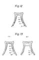
- step portions 49, 49 are formed in the guide grooves 48, 48 at only one location
- upper stop portions 15, 15 are formed at the lower ends of the resilient pieces 20, 20
- lower stop portions 16, 16 are formed on the resilient pieces 20, 20 at positions slightly above the lower ends thereof. This makes an operation similar to that described above possible, as should be apparent from Fig. 13.
- the nose-pad member 25 is attached integrally to the main body of the spectacle frame.
- the sensation is no different from that of an ordinary spectacle frame.
Landscapes
- Physics & Mathematics (AREA)
- Health & Medical Sciences (AREA)
- General Physics & Mathematics (AREA)
- Ophthalmology & Optometry (AREA)
- Optics & Photonics (AREA)
- Eyeglasses (AREA)
Applications Claiming Priority (4)
| Application Number | Priority Date | Filing Date | Title |
|---|---|---|---|
| JP198840/86 | 1986-12-26 | ||
| JP19884086U JPS63105117U (de) | 1986-12-26 | 1986-12-26 | |
| JP254709/87 | 1987-10-12 | ||
| JP25470987A JPH0697313B2 (ja) | 1987-10-12 | 1987-10-12 | 多焦点用眼鏡枠 |
Publications (2)
| Publication Number | Publication Date |
|---|---|
| EP0273650A2 true EP0273650A2 (de) | 1988-07-06 |
| EP0273650A3 EP0273650A3 (de) | 1990-04-04 |
Family
ID=26511201
Family Applications (1)
| Application Number | Title | Priority Date | Filing Date |
|---|---|---|---|
| EP19870311143 Withdrawn EP0273650A3 (de) | 1986-12-26 | 1987-12-17 | Brillengestell für Multifokalbrillen |
Country Status (10)
| Country | Link |
|---|---|
| US (2) | US4861151A (de) |
| EP (1) | EP0273650A3 (de) |
| KR (1) | KR880008054A (de) |
| AU (1) | AU606106B2 (de) |
| DK (1) | DK680287A (de) |
| ES (1) | ES2005743A6 (de) |
| FR (1) | FR2609182B1 (de) |
| IT (2) | IT8768113A0 (de) |
| NO (1) | NO875379L (de) |
| PH (1) | PH25269A (de) |
Cited By (7)
| Publication number | Priority date | Publication date | Assignee | Title |
|---|---|---|---|---|
| FR2634909A1 (fr) * | 1988-07-26 | 1990-02-02 | Bolle G R M Ets | Lunette comportant des moyens de fixation rapide des branches et du repose-nez |
| FR2647558A1 (fr) * | 1989-05-24 | 1990-11-30 | Semeph | Dispositif a usage de lunettes, notamment pour applications medicales |
| FR2652167A1 (fr) * | 1989-09-15 | 1991-03-22 | Bolle G R M Ets | Lunette comprenant un repose-nez demontable. |
| GB2239958A (en) * | 1990-08-31 | 1991-07-17 | Sam Joel Mendel | Spectacle frame having adjustable nose members |
| EP0772065A1 (de) * | 1995-11-02 | 1997-05-07 | NEGISHI, Tohru | Ophthalmische Montage für Bifokallinsen |
| WO2000043826A1 (en) * | 1999-01-25 | 2000-07-27 | Giorgio Origlia | Eyeglasses with improved functionality |
| EP1376200A1 (de) * | 2002-06-24 | 2004-01-02 | Pretolani, Francesco & C. S.n.c. | Brille mit verstellbarem Nasengleitstück |
Families Citing this family (15)
| Publication number | Priority date | Publication date | Assignee | Title |
|---|---|---|---|---|
| USD319066S (en) | 1988-11-03 | 1991-08-13 | Establissments Bolle S.N.C. | Sunglasses |
| USD321522S (en) | 1988-11-04 | 1991-11-12 | Establissements Bolle S.N.C. | Sunglasses |
| DE4118018C1 (de) * | 1991-06-01 | 1992-05-07 | Uvex Winter Optik Gmbh, 8510 Fuerth, De | |
| US5386254A (en) * | 1993-07-19 | 1995-01-31 | Kahaney; Alan | Sunglasses assembly |
| USD392991S (en) | 1995-04-07 | 1998-03-31 | Etablissements Bolle S.N.C. | Eyeglasses with side shields |
| USD387084S (en) * | 1995-04-07 | 1997-12-02 | Etablissements Bolle' S.N.C. | Eyeglasses |
| USD380227S (en) * | 1995-04-07 | 1997-06-24 | Etablissements Bolle S.N.C. | Eyeglasses with ventilating bridge |
| DE19907777A1 (de) * | 1999-02-24 | 2000-08-31 | Thomas Otto | Brille mit verstellbarer optischer Wirkung |
| USD502205S1 (en) * | 2002-09-28 | 2005-02-22 | Eston Bullard, Jr. | Adjustable eyeglass frames |
| USD565634S1 (en) * | 2005-02-19 | 2008-04-01 | Bullard Jr Eston | Adjustable eyeglass frame |
| US7637609B1 (en) * | 2006-02-24 | 2009-12-29 | Chic Optic, Inc. | Resilient hinge for eyeglasses |
| DE102006055337A1 (de) * | 2006-11-23 | 2008-06-05 | Rodenstock Gmbh | Brillenfassung, Brille und Verwendung |
| USD651641S1 (en) | 2009-09-28 | 2012-01-03 | Sperian Eye & Face Protection, Inc. | Nose piece assembly for safety eyewear |
| CN204807826U (zh) * | 2012-09-28 | 2015-11-25 | 赫马瑞斯股份有限公司 | 眼镜中梁元件、眼镜中梁元件组、眼镜架、眼镜或眼镜组 |
| US10018852B2 (en) | 2014-06-13 | 2018-07-10 | Visualign, Llc | Eyeglass positioning device |
Family Cites Families (10)
| Publication number | Priority date | Publication date | Assignee | Title |
|---|---|---|---|---|
| US2121336A (en) * | 1937-03-05 | 1938-06-21 | Abraham H Bricker | Bifocal eyeglass mounting |
| US2277726A (en) * | 1940-01-03 | 1942-03-31 | American Optical Corp | Ophthalmic mounting |
| US2486881A (en) * | 1947-05-19 | 1949-11-01 | Roth Aaron | Vertically adjustable attachment for bifocal spectacles |
| US2685819A (en) * | 1950-04-21 | 1954-08-10 | Page Louis John | Adjustable ophthalmic mounting |
| JPS5245354A (en) * | 1975-10-07 | 1977-04-09 | Mitsue Sato | Spectacle frame |
| JPS5910588B2 (ja) * | 1976-06-25 | 1984-03-09 | 工業技術院長 | 集積回路素子 |
| JPS552404A (en) * | 1978-06-20 | 1980-01-09 | Ohashi Masao | Matter waves generator |
| AU6001880A (en) * | 1980-07-01 | 1982-01-07 | Greenfield, Allan | Eyeglasses |
| GB2110417B (en) * | 1981-04-17 | 1984-08-30 | Tohru Negishi | Spectacle frame for multi-focus spectacles |
| AU560968B2 (en) * | 1982-07-16 | 1987-04-30 | Engelhardt Eyewear Pty Ltd | Adjustable spectacle frame |
-
1987
- 1987-12-15 US US07/133,489 patent/US4861151A/en not_active Expired - Lifetime
- 1987-12-15 AU AU82572/87A patent/AU606106B2/en not_active Ceased
- 1987-12-17 EP EP19870311143 patent/EP0273650A3/de not_active Withdrawn
- 1987-12-22 DK DK680287A patent/DK680287A/da not_active Application Discontinuation
- 1987-12-22 NO NO87875379A patent/NO875379L/no unknown
- 1987-12-23 PH PH36294A patent/PH25269A/en unknown
- 1987-12-23 IT IT8768113A patent/IT8768113A0/it unknown
- 1987-12-23 ES ES8703720A patent/ES2005743A6/es not_active Expired
- 1987-12-23 FR FR8718096A patent/FR2609182B1/fr not_active Expired - Lifetime
- 1987-12-24 KR KR870014862A patent/KR880008054A/ko not_active Withdrawn
-
1989
- 1989-04-11 US US07/338,934 patent/US4925292A/en not_active Expired - Fee Related
- 1989-12-14 IT IT5354689U patent/IT8953546U1/it unknown
Cited By (10)
| Publication number | Priority date | Publication date | Assignee | Title |
|---|---|---|---|---|
| FR2634909A1 (fr) * | 1988-07-26 | 1990-02-02 | Bolle G R M Ets | Lunette comportant des moyens de fixation rapide des branches et du repose-nez |
| US5032017A (en) * | 1988-07-26 | 1991-07-16 | Etablissements Bolle Georges, Robert Et Maurice | Spectacles comprising means for quickly fitting the side-pieces and the nose-piece |
| FR2647558A1 (fr) * | 1989-05-24 | 1990-11-30 | Semeph | Dispositif a usage de lunettes, notamment pour applications medicales |
| FR2652167A1 (fr) * | 1989-09-15 | 1991-03-22 | Bolle G R M Ets | Lunette comprenant un repose-nez demontable. |
| GB2239958A (en) * | 1990-08-31 | 1991-07-17 | Sam Joel Mendel | Spectacle frame having adjustable nose members |
| GB2239958B (en) * | 1990-08-31 | 1992-03-04 | Sam Joel Mendel | Height adjustable spectacles |
| EP0772065A1 (de) * | 1995-11-02 | 1997-05-07 | NEGISHI, Tohru | Ophthalmische Montage für Bifokallinsen |
| US5691796A (en) * | 1995-11-02 | 1997-11-25 | Negishi; Tohru | Ophthalmic mounting for bifocal lenses |
| WO2000043826A1 (en) * | 1999-01-25 | 2000-07-27 | Giorgio Origlia | Eyeglasses with improved functionality |
| EP1376200A1 (de) * | 2002-06-24 | 2004-01-02 | Pretolani, Francesco & C. S.n.c. | Brille mit verstellbarem Nasengleitstück |
Also Published As
| Publication number | Publication date |
|---|---|
| AU606106B2 (en) | 1991-01-31 |
| US4861151A (en) | 1989-08-29 |
| IT8953546U1 (it) | 1991-06-17 |
| KR880008054A (ko) | 1988-08-30 |
| ES2005743A6 (es) | 1989-03-16 |
| US4925292A (en) | 1990-05-15 |
| EP0273650A3 (de) | 1990-04-04 |
| AU8257287A (en) | 1988-06-30 |
| DK680287A (da) | 1988-06-27 |
| IT8953546V0 (it) | 1989-12-14 |
| NO875379D0 (no) | 1987-12-22 |
| IT8768113A0 (it) | 1987-12-23 |
| DK680287D0 (da) | 1987-12-22 |
| FR2609182B1 (fr) | 1991-09-20 |
| NO875379L (no) | 1988-06-27 |
| FR2609182A1 (fr) | 1988-07-01 |
| PH25269A (en) | 1991-03-27 |
Similar Documents
| Publication | Publication Date | Title |
|---|---|---|
| US4861151A (en) | Frame for multifocal spectacles | |
| US4951322A (en) | Detachable mono-glass sports goggles | |
| JPH0259444B2 (de) | ||
| JPS60146218A (ja) | 眼鏡フレームおよびこれに取り付ける眼鏡フロント用支持構造体 | |
| US6227665B1 (en) | Sport eyeglasses having removable lenses | |
| US4848891A (en) | Temple biasing means | |
| US4113365A (en) | Spectacles' frame with vertically adjustable nose pads | |
| EP0418019A1 (de) | Tragbares Fernglas | |
| KR20230048231A (ko) | 무게분산 안경테 | |
| US4169665A (en) | Eyeglass bow construction | |
| JP3421775B2 (ja) | 眼鏡用鼻パッド | |
| US12443051B2 (en) | Nose pad adjustment assembly | |
| US20230132938A1 (en) | Sunglasses for use in water activities | |
| KR101933627B1 (ko) | 스포츠용 고글 | |
| US4728182A (en) | Bi-focal contact lens | |
| JPH032892Y2 (de) | ||
| US2708269A (en) | Eye shade | |
| JPH0697313B2 (ja) | 多焦点用眼鏡枠 | |
| JPS5921003B2 (ja) | 多焦点用眼鏡枠 | |
| JPH0227647B2 (de) | ||
| KR200310430Y1 (ko) | 높이 조절 안경 | |
| CN219811097U (zh) | 一种可调松紧度的金属脚丝眼镜 | |
| US407789A (en) | Self-adjusting eyeglass-frame | |
| KR200218588Y1 (ko) | 산업용 안경 | |
| CN216118249U (zh) | 一种防脱落的视力矫正眼镜 |
Legal Events
| Date | Code | Title | Description |
|---|---|---|---|
| PUAI | Public reference made under article 153(3) epc to a published international application that has entered the european phase |
Free format text: ORIGINAL CODE: 0009012 |
|
| AK | Designated contracting states |
Kind code of ref document: A2 Designated state(s): AT CH DE GB LI NL SE |
|
| PUAL | Search report despatched |
Free format text: ORIGINAL CODE: 0009013 |
|
| AK | Designated contracting states |
Kind code of ref document: A3 Designated state(s): AT CH DE GB LI NL SE |
|
| 17P | Request for examination filed |
Effective date: 19901002 |
|
| STAA | Information on the status of an ep patent application or granted ep patent |
Free format text: STATUS: THE APPLICATION HAS BEEN WITHDRAWN |
|
| 18W | Application withdrawn |
Withdrawal date: 19911209 |