EP0273820A2 - Datenkomprimierungsvorrichtung und Verfahren zum Datenaufzeichnen - Google Patents
Datenkomprimierungsvorrichtung und Verfahren zum Datenaufzeichnen Download PDFInfo
- Publication number
- EP0273820A2 EP0273820A2 EP87402833A EP87402833A EP0273820A2 EP 0273820 A2 EP0273820 A2 EP 0273820A2 EP 87402833 A EP87402833 A EP 87402833A EP 87402833 A EP87402833 A EP 87402833A EP 0273820 A2 EP0273820 A2 EP 0273820A2
- Authority
- EP
- European Patent Office
- Prior art keywords
- data samples
- predetermined number
- input
- frequency
- compression
- Prior art date
- Legal status (The legal status is an assumption and is not a legal conclusion. Google has not performed a legal analysis and makes no representation as to the accuracy of the status listed.)
- Withdrawn
Links
Images


Classifications
-
- H—ELECTRICITY
- H03—ELECTRONIC CIRCUITRY
- H03M—CODING; DECODING; CODE CONVERSION IN GENERAL
- H03M7/00—Conversion of a code where information is represented by a given sequence or number of digits to a code where the same, similar or subset of information is represented by a different sequence or number of digits
- H03M7/30—Compression; Expansion; Suppression of unnecessary data, e.g. redundancy reduction
Definitions
- the present invention relates generally to data compression and data recorders, and more particularly relates to data compression techniques for use in electrical power line fault detectors/recorders which allow a reduction in the amount of information to be stored, transmitted, or analyzed in connection with the detection/recording and analysis of a fault condition on an electrical power transmission line.
- data recorders monitor electrical power lines for signal fluctuations indicative of problems in the transmission line.
- Typical power line fault recorders record analog data from the voltages and currents on the transmission lines emanating from substations and generation stations.
- Some conventional data recorders operate constantly even when no problems are present, generating enormous amounts of data which yield little useful information.
- a skilled analyst can examine the characteristics of the data (such as rise times, transient characteristics, and durations of signals) and ascertain the location and nature of the fault.
- the data must be transmitted via a telephone line and modem link, or physically transported on a medium such as magnetic tape. Needless to say, transmission of large amounts of data at standard rates of 2400 baud is inordinately slow, and storage of such data on magnetic tape is not a preferable alternative because of the weight and bulk of the reels or cartridges of tape. While often the resolution of the data is not critical for graphic display, the speed of acquiring the data is essential so that the power outage time can be minimized.
- CME continuous monitoring equipment
- the CME requires a finite amount of time to detect the occurrence of a fault.
- a predetermined amount of data prior to the occurrence of the fault must somehow be saved for analysis, since the data immediately prior to the fault often provides the most useful information as to the nature of the fault.
- electrical utility CME continuously record data and store it in a temporary buffer so that when a fault is recognized, the data in the temporary buffer prior to the fault plus data corresponding to the fault is preserved.
- Data recording for other applications such as seismic recording and nuclear testing also produce vast amounts of data which must be either recorded at high speed, buffered, or compressed for later analysis.
- digital tape drives are employed for saving the data into a permanent storage medium for subsequent analysis.
- Typical magnetic tape drives used in such data recorders can operate at speeds of up to 100 inches per second, for nine tracks with a packing density of 1600 bits per inch per track. Although these are high density, high speed recorders, in some applications the amount of data being accumulated to provide the desired resolution is greater than the recording ability of the tape drives, requiring either multiple tape drives or data compression schemes.
- data compression techniques are frequently used to reduce the volume of data prior to storage or transmission. These techniques can result in greater transmission speeds and storage densities.
- Many types of data compression techniques are known in the art. These techniques fall basically into two primary categories: (1) logical compression (also called “redundancy reduction”) and (2) physical compression (also called “entropy reduction”).
- Logical compression is a data dependent technique and results from the elimination of redundant fields of information while representing data elements in remaining fields with as few logical indicators or codes as is feasible.
- Physical compression or entropy reduction is typically viewed as the process of reducing the quantity of data prior to it entering a transmission channel or storage medium and the subsequent expansion of such data to its original format upon receipt or recall. Physical compression necessarily results in loss of information, since data which may contain useful information is deliberately discarded.
- One particular compression technique employed in seismologic recording involves a gain-switchable analog-to-digital converter which selects one of four different gain ranges for a particular data sample. Two bits of data are added to each digital data sample for encoding gain information. Thus, at the instant of sampling, a two-bit gain code is obtained representative of which one of four possible amplitude ranges is associated with the sample. The gain code is used to select one of four analog amplifiers on the input to the D/A converter prior to digitizing the sample. The digital output of the D/A converter, plus the two-bit gain code, then constitutes the reduced data. While this technique results in a degree of data compression and reduced bandwidth, it fails to take advantage of the fact that a plurality of consecutive samples may have the same gain code, resulting in the transmission of much redundant information. Thus, the compression efficiency for this scheme is not particularly great.
- the present invention provides an improved data compression method and apparatus.
- the technique is particularly suitable for use in power line fault monitoring equipment, but may also find application in other types of data recorders.
- the system performs the data compression by receiving a predetermined number of digital input data samples representing an input information signal during a sampling period. The samples are then analyzed to obtain a compression parameter corresponding to the magnitude of an information parameter of the input information signal.
- the information parameter can be amplitude
- the compression parameter can be a gain compression factor or code which is related to the magnitude of the amplitude of the input signal at its peak level during the sampling.
- the information parameter can be frequency
- the compression parameter can be a frequency compression factor or code which is related to the highest frequency component contained in the information signal during the sampling which exceeds a predetermined threshold magnitude.
- a predetermined portion of the data samples is selected in response to the compression parameter to provide a second predetermined number of compressed digital data samples.
- the second predetermined number of compressed data samples contains less data than the original input samples. For example, if gain compression is performed, then there is provided the same number of compressed data samples, but each sample has fewer bits than the original input samples. If frequency compression is performed, then there are provided fewer compressed data samples by discarding unneeded samples.
- the system provides a compressed data stream comprising (1) a word containing the compression parameter and (2) the second predetermined number of compressed data samples.
- the present invention operates in a manner somewhat analogous to adaptive sampling. However, in the present invention the data is sampled at an extremely high rate so as to preserve all information as to signal amplitude and frequency components. Then, the data is reduced by gain ranging and/or frequency ranging to reduce the amount of data that is actually stored or transmitted after sampling.
- the apparatus and method comprises providing a predetermined number n of input data samples, each sample having a word length of M bits.
- the system is responsive to detect the highest magnitude of the input signal during the sampling period of n samples.
- the compression method involves selecting a predetermined number k bits of each one of the data samples, where k is less than m. There is then provided a predetermined number n of n k- bit compressed data samples, plus a gain code which corresponds to the detected greatest magnitude of the samples in the set of n samples.
- FFT fast Fourier transform
- the highest frequency of interest does not usually exceed 1500 Hz.
- the set of input samples is reduced by discarding data samples until the remaining data samples are sufficient in number to satisfy the Nyquist criterion for the highest frequency of interest, namely, 60 Hz.
- both the gain compression and the frequency compression methods are employed back-to-back, resulting in the provision of r compressed words of k bits each, from an input sample set of n words of m bits each.
- the present invention both reduces the redundant gain information which may be present in the set of input data, as well as the information content or entropy of the input data by discarding data samples which are not required to reproduce the highest frequency of interest in the input data set.
- the invention therefore allows greater efficiencies in the transmission of data via telecommunications links such as via modem and telephone line, plus greater data packing densities on recording media such as magnetic tape and disk.
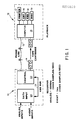
- FIG. 1 shows a preferred embodiment of a data recorder 10 and playback unit 12 constructed in accordance with the present invention.
- a system comprising one or more recorders 10 connected by a telephone line 13, or alternatively by physical transfer of data tape cartridges 14, is particularly suitable for use as an electricity fault data recorder.
- recorders 10 connected by a telephone line 13, or alternatively by physical transfer of data tape cartridges 14, is particularly suitable for use as an electricity fault data recorder.
- other types of data recorders such as seismic data recorders or other scientific instrumentation data recorders, may also find application of the present invention.
- the recorder 10 which is configured for use as an electricity power line fault data recorder.
- the recorder 10 comprises a data input section 20 which is connected via a signal bus 21 to a control section 22.
- the bus 21 is an IEEE 488 bus, the construction of which will be familiar to those skilled in the art.
- the data input section 20 and the control section 22 are illustrated in more detail in Figs. 2 and 3, respectively.
- the playback unit 12 comprises circuitry including a computer 15 and software which is responsive to compressed data received either over the telephone line 13, or alternatively received on tape cartridges 14, to reproduce the analog signal represented by the compressed data.
- the playback unit 12 comprises an International Business Machines (IBM) corporation personal computer (PC) 15 which is programmed to reverse the process to be described hereinbelow for data compression, thereby obtaining an analog signal which can be graphically displayed on a CRT monitor 16, or reproduced on a printer 17, for analysis by a person skilled in the art of power line fault analysis.
- the playback unit 12 will further include a keyboard 18 for data entry and control by the operator, and a hard disk 19 or other mass storage medium for storage of the data.
- the data input section 20 of the recorder is configured to receive several different types of inputs.
- the preferred data input section 20 illustrated in Fig. 2 is configured to monitor voltages and currents, as well as switch closures and openings which typically accompany a power line fault. For example, power line faults often trigger the opening of circuit breakers, and the location and timing of these "events" bear information as to the nature and location of the fault.
- the data input section in the preferred embodiment comprises an analog signal processor 25 and an event processor 26.
- the analog signal processor 25 includes a plurality of input channels for monitoring electrical voltages and currents. Where the system is to monitor a voltage parameter, terminals 30 are provided. If a current input is to be monitored, terminals 31 would be employed, which are connected across a shunt resistor R. Each of the terminals 30, 31, whether voltage or current, are provided to the input of a high impedance input scaling amplifier such as indicated at 32. These amplifiers, which are conventional in nature, scale the input signal excursion to be within the operational limits of subsequent circuit stages. The outputs of the input scaling amplifiers 32 are then provided through isolation amplifiers 34 so as to provide isolation between logic ground of the circuitry and the inputs. Preferably, circuit components providing about 2500 volts AC isolation are provided.
- the outputs of the isolation amplifiers 34 are provided through anti-aliasing or low pass filters 35 to the inputs of an analog multiplexer (MUX) 37.
- the anti-aliasing filter band limits the input signal to the highest frequency of interest, 1920 Hz in the preferred embodiment.
- the analog multiplexer 37 is a conventional four-to-one analog multiplexer such as a type AD7502 manufactured by Analog Devices, Inc., Norwood, Massachusetts.
- the SELECT lines 38 for the multiplexer 37 are provided from the data input motherboard 28 which receives signals from the other components in the recorder, as will be described later.
- the multiplexer 37 is selectable so that the output of the multiplexer on line 39 is connected to one of a plurality of input terminals.
- the multiplexer 37 cycles through or "polls" by rotating among the input channels.
- the data rate of the system is to sample each of the inputs sixty-four times per line cycle. This corresponds to 3840 samples per second for each input. Accordingly, the multiplexer cycles through four inputs at a rate four times the sampling rate, or 15,360 Hz.
- the output of the multiplexer on line 39 is provided to a data compression circuit 40, wherein the method of the present invention is carried out.
- the output of the data compression circuit is a digital data stream provided on lines 42 to the data input mother board.
- the event processor 26 comprises means for detecting the occurrence of particular events, such as the opening of a circuit breaker in an electrical power facility. This capability allows the system to determine the time at which crucial events have taken place so that these events can be correlated to the characteristics of the signals being sampled by the analog signal processor 25.
- the event processor 26 comprises a plurality of test switches 43 and event input switches 44 which are connected through optoisolators 45 into a microprocessor circuit 46.
- the microprocessor 46 is a conventional microprocessor which merely detects the occurrence of the closure of one of the event switches 44 and provides a digital signal via lines 47 indicating which switch was closed and the time of closure to the data input motherboard 28.
- the test switches 43 are provided solely as a troubleshooting aid.
- a conventional IEEE 488 bus control circuit 48 is provided for conducting signals from the analog signal processor 25 and the event processor 26 to the control section 22.
- the bus control circuit 48 is connected to the data input motherboard 28, and provides signals over the IEEE 488 bus 21 to the circuitry illustrated in Fig. 3.
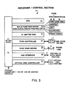
- the control section 22 comprises a conventional International Business Machines (IBM) personal computer (PC) or compatible computer system 50 which can be configured with various peripheral devices plugged into a PC motherboard 51 in the manner known to those skilled in the art.
- Peripherals employed in the preferred embodiment include a conventional multifunction board 52 which include random access memory (RAM), a real-time clock, RS232 standard interface connections, printer ports, and a CRT port. Attached to the multifunction board, or otherwise associated with the computer, are peripherals such as a printer, a CRT, a keyboard, a time code generator, and a front panel.
- IBM International Business Machines
- PC personal computer
- compatible computer system 50 which can be configured with various peripheral devices plugged into a PC motherboard 51 in the manner known to those skilled in the art.
- Peripherals employed in the preferred embodiment include a conventional multifunction board 52 which include random access memory (RAM), a real-time clock, RS232 standard interface connections, printer ports, and a CRT port. Attached to the multifunction
- the time code generator may be provided if a highly accurate clock is desired which can be synchronized by a GEOS (geostationary earth orbit satellite) satellite, a WWV, or microwave link from an external source.
- a front panel may include alarm indicators and switches for turning the system on and off, and for configuring the system to record or not.
- Additional peripherals attached to the PC motherboard 51 and shown in Fig. 3 include a RAM board 53 which serves as the data buffer for the compressed data samples.
- a RAM board 53 which serves as the data buffer for the compressed data samples.
- two megabytes of RAM storage are provided so that all data corresponding to a fault may be stored until removed by transferring to tape or by transmitting over a communications link.
- a tape controller 54 is provided in the preferred embodiment for controlling a tape drive for mass data storage on magnetic tape cartridges 14.
- a 2400 baud modem 55 is provided for connection to a telephone line 13 for transmission of data to the playback unit 12 which may be located off site.
- An IEEE 488 interface board 56 provides a connection to the 488 bus control circuit 48 in the data input section 20.
- a mass storage device such as an optical disk may be provided, which is controlled in the preferred embodiment by an optical disk controller 57.
- a set of digitized data samples are analyzed and the sample having the greatest magnitude identified.
- the precompression data appears as shown in the left-hand portion of the figure. An inspection of these data samples will reveal that data sample 2 contains the sample having the greatest magnitude of the set of n samples. Assume further that the output data stream is to be reduced to n 8-bit data values. Accordingly, four bits of resolution must be removed from the precompressed samples.
- n 8-bit samples Associated with the n 8-bit sample will be a gain code, which in the preferred embodiment is transmitted as the first 8-bit word of information.
- the gain code word comprises five consecutive "ones" for synchronization, and three bits of gain information which signify which four bits of each sample have been discarded.
- the gain compression parameter or gain code provided in the preferred embodiment is related to the magnitude of the amplitude of the input signal during the sampling period, wherein a first predetermined number n samples were obtained.
- the method of the present invention selects a predetermined number k bits of each one of the data samples, where k is less than m to provide a second predetermined number r of k-bit compressed data samples.
- the first predetermined number of data samples n equals the second predetermined number r of compressed data samples.
- the number of samples processed for gain compression is not necessarily the same as the number of samples processed for frequency compression, as will be discussed later.
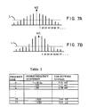
- the present invention also performs what may be termed "frequency ranging". This involves providing only a sufficient number of samples of the input signal to satisfy the Nyquist criterion for the highest frequency of interest in the signal. For example, in power line monitoring the applications, there will most often be a fundamental frequency component at 60 Hz. Upon the occurrence of a fault, higher order harmonics of 60 Hz will often be present. One such situation is illustrated in Fig. 7A, where F equals 60 Hz. It will be observed that there are frequency components as high as 7F in this example.
- the data samples are decimated or reduced so that information pertaining to frequency components above 4F are not preserved. In other words, data samples are discarded until there remain only a sufficient number of data samples to satisfy the Nyquist criterion for frequency 4F.
- the magnitude of each frequency component is examined to ascertain whether each frequency component is contributing in a significant manner to the representation of the input signal. Stated in other words, when the frequency components exceed a predetermined threshold level such as designated at L, the components are deemed significant and a sufficient number of data samples should be preserved for reproducing the signal.
- sampling must occur at a rate higher than 480 Hz, say, 640 samples per second. Accordingly, if 3840 samples per second have been taken, then one-sixth of this number, or 640 would suffice to satisfy the Nyquist criterion. It will therefore be appreciated that five out of each consecutive six samples can be discarded, while still providing an effective sampling rate of 640 Hz.
- the sampling must occur at a rate exceeding 360 Hz, say 480 Hz, in order to satisfy the Nyquist criterion.
- 360 Hz say 480 Hz
- the method involves only retaining one of every eight consecutive samples and discarding the other seven.
- one method of the present invention involves determining the highest frequency component in the input information signal which exceeds a predetermined threshold magnitude during a sampling period. This is accomplished in the alternative embodiment by employing a conventional FFT algorithm in the computer 50 to obtain the frequency components, and by then comparing each frequency component to a threshold until the highest frequency of interest above the threshold is identified. Then the set of n input data samples is decimated, leaving a set of a second predetermined number n reduced data samples.
- n there are n data samples (n being 3840 in the example discussed)
- a set of r ⁇ n compressed data samples which are derived by decimating the predetermined number n data samples as a function of the highest frequency component present to obtain a second predetermined number r of data samples.
- the predetermined number r data samples remaining after decimation corresponds to the Nyquist criterion based on the highest frequency component present in the input signal.
- the frequency compression parameter provided is an indication of the highest frequency component in the set of compressed data samples.
- the frequency compression parameter is a number which is related to the time period between successive ones of the predetermined number r of compressed data samples. This is illustrated in Table I.
- the frequency compression parameter may signify an integral sequence of retained samples. For example, if the highest frequency of interest is 930 Hz, sampling should occur at no less than 1860 Hz in order to satisfy the Nyquist criterion. Inasmuch as 1920 Hz is sufficient to satisfy the criterion, and inasmuch as there are exactly twice this number of samples in the input set of n samples, then by discarding every other sample, there will be retained sufficient samples to reproduce 930 Hz. In this case, a frequency compression parameter of the integral number "two" signified that every other sample is discarded.
- the output data for the disclosed frequency ranging methods is provided as a stream of r data samples preceded by a frequency code word which signifies the time between data samples or the integral sequence of retained samples.
- Circuitry receiving the compressed data stream then can reconstruct the signal by converting the digital samples to analog form as a function of the frequency code (which in both embodiments described represents the time which it occurred between the data samples being provided to the digital-to-analog converter).
- gain ranging and frequency ranging are combined back-to-back in order to obtain a highly compressed data stream.
- the number of data samples ultimately transmitted may be provided as a function of the frequency components present in the input signal, while the scaling of the output samples is provided as a function of the highest gain excursion present in the input data samples.
- a pair of code words preceding a set of r data samples where r is less than the number n of input data samples, and where each data sample has k bits, where k is less than the number m of bits in each input data sample.
- the data compression circuit 40 preferably comprises a gain compression subsection 60 and a frequency compression subsection 70.
- analog samples of the input signals are provided on line 39 to the data compression circuit 40.
- This analog signal is provided first to the gain compression subsection 60, and particularly to a 12-bit analog-to-digital (A/D) converter 61 for conversion of the sample into a 12-bit digital word.
- A/D analog-to-digital
- These samples are then provided on lines 62 to a first-in-first-out (FIFO) buffer 64 and to a gain ranging circuit 65.
- FIFO first-in-first-out
- the output of the first-in-first-out buffer 64 is provided to a gain switch 66 which selects a particular eight of the 12 bits of data to provide an eight-bit output word.
- the gain ranging circuit 65 is responsive to detect the greatest amplitude sample in a set of n input samples, and provide a three-bit GAIN CODE on lines 67. Where gain compression is the only compression taking place, the output of the gain compression subsection 60 is an eight-bit word COMPRESSED DATA (Format A) on lines 67 and a three-bit GAIN CODE provided on lines 68. Collectively, these signals appear on lines 42.
- gain ranging and frequency ranging are both provided.
- the eight-bit output of the gain switch 66 in the gain compression subsection 60 is provided to a frequency ranging subsection 70, and in particular to a random access memory (RAM) buffer 74 contained therein.
- RAM buffer 74 is 4,096 eight-bit words for ease of addressing.
- the GAIN CODE on line 68 is also provided to the frequency ranging subsection 70, and in particular to a frequency ranging circuit 75. It will of course be understood by those skilled in the art that the GAIN CODE, which relates to the magnitudes of the input samples, is required by the FFT algorithm employed in the alternative embodiment in order to obtain the magnitude of the frequency components.
- the output of the frequency ranging circuit 75 is a twelve-bit address provided on lines 76 to the RAM buffer 74.
- the addresses on lines 76 are used to select predetermined ones of the data samples stored in the RAM buffer so as to decimate the predetermined number n data samples to obtain the second predetermined number r of compressed data samples.
- the output of the frequency ranging circuit 70 which is the combination frequency and gain compressed data, is a three-bit GAIN CODE, a five-bit FREQUENCY CODE, and an eight-bit COMPRESSED DATA word, provided on lines 42.
- frequency rang ing is effectuated by a downward/upward decimation method.
- the input data samples are first decimated to remove samples, and after this "downwards" decimation, an "upwards” decimation or interpolation is performed in an effort to recreate or reconstruct the input signal from the decimated data samples.
- the reconstructed signal is then compared to the original input signal, on a point by point basis, employing conventional digital comparison techniques. If the input signal and the reconstructed signal compare within a predetermined error percentage, then it is established that the signal can be adequately reproduced at the other end of the communications channel or upon retrieval from storage. Accordingly, the compressed signal is then transmitted or stored in the described manner.
- the reconstructed signal does not match the original signal within the predetermined error percentage, it is indicated that too many data samples were removed. Accordingly, the downwards decimation process is repeated, removing fewer data samples. Then, the upwards decimation or interpolation process is repeated, and the resultant set of samples again used to reconstruct the input signal. The comparison to the input signal is repeated, and again a determination is made whether the reconstructed signal matches the input signal within a predetermined error percentage. These steps are repeated until the reconstructed signal matches the input signal within a predetermined error percentage.
- the steps of comparing the original data with the reconstructed data merely comprises subtraction operations by the computer, and comparison of the difference to a predetermined acceptable tolerance or error on a point by point basis.
- Programming the computer 50 in order to carry out such a method is within the skill of the art.
- the predetermined acceptable tolerance is an operator settable parameter.
- one primary object of the present invention is to be able to reconstruct the input signal for purposes of acceptable graphic display at the end of a communications link, those skilled in the art will understand that what is considered "acceptable" reproduction for graphic display may vary depending upon the personal preferences of the analyst or the exigencies of the moment.
- frequency ranging is effectuated by employing a commercially available FFT program on the IBM PC 50.
- the eight-bit gain compressed data samples provided on lines 67 from the gain ranging circuit 60, plus the three-bit gain code on lines 68, are provided via the 488 bus control circuit 458 to the IBM PC CPU and stored in RAM 53 (Fig. 3).
- RAM 53 in Fig. 3 thus performs the function of RAM buffer 74 in Fig. 4.
- FFT's are typically performed on sample sizes which are an even power of two, typically 1024, and that there is no relation to the number of input samples per second. Accordingly, it will be understood that the FFT algorithm must be able to compute rapidly enough to stay ahead of the input data stream if real time compression is desired. If off line computation is employed, then of course the speed of the FFT algorithm is not as crucial.
- the program in the IBM PC executes the FFT program to obtain the frequency components present in the samples. Then, the steps illustrated in Fig. 8 and described hereinbelow are executed to decimate the sample set to obtain a reduced set of r frequency-compressed samples.
- the steps illustrated in Fig. 8 and described hereinbelow are executed to decimate the sample set to obtain a reduced set of r frequency-compressed samples.
- Fig. 5 illustrates the gain compression subsection 60 (Fig. 4) in more detail.
- the analog input provided on line 39 is provided to a 12-bit A/D converter 61, the 12 outputs of which are provided on lines 62.
- a type ADC80-12 manufactured by Analog Devices, Norwood, Massachusetts is employed.
- the CONVERT input of the A/D converter 61 is connected to a signal labeled CONVERT on line 81 from a timing and control circuit (not illustrated).
- a timing and control circuit not illustrated.
- the CONVERT signal should be provided on a periodic basis related to the sampling rate. As discussed hereinabove, the sampling rate in the preferred embodiment is 3840 Hz; accordingly, the CONVERT signal will occur at this rate.
- the CONVERT signal is also provided to a divide-by-sixty circuit 82, the output of which provides a signal designated as PERIOD.
- the PERIOD signal signifies the end of a 60 sample set of data. It will be appreciated that the PERIOD signal will occur once for each set of 60 samples for the preferred embodiment.
- the multiplexer 37 (Fig. 2) provides analog samples from four different inputs, it will be understood that the timing of the CONVERT and PERIOD signals must be altered for multiplexed arrangements, and that the circuit illustrated in Fig. 5 merely illustrates the circuit for use in a non-multiplexed arrangement.
- the PERIOD signal is provided to the reset input of a counter 84 which is used to address the FIFO memory 64.
- the CONVERT signal is provided to the clock input of the counter 84 for causing the counter to increment.
- Six bits of counter output are provided from the counter 84 to the address inputs of the FIFO 64.
- the FIFO memory 64 in the preferred embodiment is a 12 bit by 60 word memory such as may be constructed by cascading five sets of three type 74ALS232 16 ⁇ 4 bit FIFO memories, manufactured by Texas Instruments.
- a type DS2001 2K ⁇ 9 bit CMOS FIFO manufactured by Dallas Semiconductor Corp., Dallas, TX, may be employed.
- the 12 bit outputs are provided to the gain switch 66, which comprises eight type 74151 data selectors/multiplexers 85a--85h manufactured by Texas Instruments. It will be observed in Fig. 5 that the inputs of the data selectors 85 are connected to receive five different ones of the 12 bits of digital data provided by the A/D converter 64 in an ascending manner. For example, the lowermost data selector 85a receives the five least significant bits of the output of the FIFO 64, while the data selector 85b receives the second through sixth least significant bits, and so on until the last data selector 85h receives the five most significant bits. Note further that the outputs Y of the data selectors 85a--85h provide the eight bit COMPRESSED DATA word. Selection between one of five bits provided to each of the data selectors is made by the three-bit GAIN CODE provided on lines 67.
- the GAIN CODE is created by the gain ranging circuit 65 in the following manner.
- the four most significant bits from the A/D converter 61 are provided to the J input of a type 74376 J- flip-flop. The input is tied high.
- the clock input of the flip-flop 90 is connected to a signal denominated CONVERT + DELAY provided on line 91. This signal is provided from control circuitry (not illustrated) which essentially delays the CONVERT signal a predetermined amount of time to allow for propagation through the A/D converter 61. When this signal occurs, the flip-flop latches and holds the occurrence of any "one" occurring on a J input until cleared.
- the J- flip-flop 90 once a "one" has been clocked into the flip-flop, will hold the one until the flip-flop is cleared.
- the flip-flop is cleared by the signal denominated PERIOD + DELAY, which is provided through an inverter 93 to the clear ( ) input. This signal occurs after 60 samples have been converted and stored in the FIFO memory 64.
- the Q outputs of the flip-flop 90 are provided to a type 74175 D-type flip-flop circuit 94 which latches the four bits of data from the flip-flop 90 on the signal PERIOD + DELAY.
- the flip-flop 94 holds the four bits of data from the J- flip-flop 90 for use in formulating and holding the gain code while reading out the 60 samples of data from the FIFO memory 64.
- the Q outputs of the flip-flop 94 are next provided to a type 74148 priority encoder 96 which converts the four bits of input data into a three-bit code denominated the GAIN CODE on line 67.
- the GAIN CODE is then connected to the select inputs A, B, C of the data selectors 85 and cause them to select one of five inputs received from the FIFO memory 64.
- the first word of data in the FIFO memory 64 reaches the outputs of the FIFO at the end of a sixty sample period. Accordingly, it will be appreciated that all sixty samples are clocked out of the FIFO 64 under the influence of the GAIN CODE formed during the sixty sample period.
- the data are then provided through the data selectors 85a--85h to form the eight bits of COMPRESSED DATA.
- the circuitry described in Fig. 5 operates to provide a new GAIN CODE for every sixty samples.
- the gain ranging circuit 65 is responsive to each sample to determine the GAIN CODE for a set of 60 samples.
- a new GAIN CODE is obtained and provided on line 67, and this value is held on line 67 as the previous 60 words in the FIFO are now in a position to be provided as outputs from the FIFO.
- the GAIN CODE remains as the samples are provided as outputs, while the J- flip-flop 90 is responsive to the next set of samples being provided and stored therein.
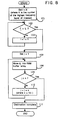
- Fig. 8 next will be described the steps taken in the alternative embodiment for decimating the sample set of n input samples to obtain a set of r frequency-compressed samples.
- Fourier analysis by way of an FFT or other frequency analysis algorithm has been performed on the set of n data samples.
- a set of data values which correspond to the magnitudes of the harmonics of the input signal during the portion of the input signal represented by the set of n data samples.
- these steps are taken by the data compression circuit 40, and in particularly by the computer 50 in the control section 22, in conjunction with other computer programs employed for controlling the overall operation of the recorder.
- the first operation conducted is to set an index i equal to a number which corresponds to the highest frequency band of interest.
- a number which corresponds to the highest frequency band of interest.
- up to 32 harmonics of the 60 Hz fundamental frequency can be represented within the Nyquist criterion with 3840 samples.
- i will be set to 14, which corresponds to the 32nd harmonic.
- Table II illustrates the relationship between the index i and the harmonics.
- the highest frequency of interest is compared to a predetermined threshold magnitude level L to determine whether there are any significant components at the frequency F i . It will be appreciated that the comparison to the threshold L begins at the highest harmonic and works downwardly, so that the presence of a significant frequency component at the highest harmonic will be detected. In the event that the frequency of interest F i does not exceed the threshold level, the "no" branch from 102 is taken to step 103, and the index i is increased by one. The first harmonic to be detected above the threshold level L causes the "yes" branch to be taken from 102 to step 105.
- an index j is initialized to one, preparatory to moving a data sample d j into memory. Then, at step 106 the data sample d j is moved into a location in the RAM buffer 74, or alternatively in the RAM 53, which has been set aside specifically for post-decimation data. Next, at 108, the index j is compared to the total number of samples n, where n is the total number of samples in the set being processed, the number being 3840 in the preferred embodiment and 1024 in the embodiment employing an FFT algorithm. If the pointer j has not passed n then the "no" branch is taken to step 110, where the pointer j is incremented by a predetermined number x. The predetermined number x is an incremental amount which is determined as a function of the number i determined at step 102.
- the predetermined number x generally increases as i decreases.
- the incremental amount x is an integral divisor of 3840, so that there are no fractional increments for j. Having integral increments results in the ability to discard particular integral numbers of samples rather than fractional numbers, which would complicate the selection of samples.
- Table II represents the situation wherein x is an integer.
- step 110 and j is incremented, the program returns to step 106, and the next data sample is moved into a memory.
- step 108 When j equals or exceeds n, then the "yes" branch is taken from step 108, and the decimation process is complete.
- the decimated data samples will now be present in the RAM buffer array, and the data will be ready for transmission or storage together with an associated frequency code which is also a function of i.
- the above-described method of the preferred embodiment for reconstructing the input signal from the decimated data set prior to transmission or storage may be employed to determine whether the input signal can be adequately reproduced.
- the steps taken involve performing an inverse operation within the system to recreate the input signal after decimation but prior to transmission or storage of the compressed data.
- the reconstructed signal is then compared to the original signal. If the signals compare within a predetermined error percentage, then it is established that the signal can be adequately reproduced at the end of the communications channel or upon retrieval from storage. Accordingly, the compressed signal is then transmitted or stored in the described manner.
- the steps of comparing the original data to the reconstructed data merely comprises subtraction operations by the computer and comparison of the difference to a predetermined acceptable difference on a point by point basis.
- the technique for deriving a reconstructed signal received over the telephone line or retrieved from a mass storage medium is simply the inverse of the gain or frequency ranging.
- the playback unit reads each eight bit word of data which is provided as a sample and places the set of samples in a temporary buffer. Each of these samples is then multiplied by the gain code provided as the first word accompanying the set of data. For example, if the two least significant bits and the two most significant bits were discarded, this would correspond to a multiplication by four.
- the frequency code is employed to determine the time between consecutive samples. After the playback unit finishes reconstructing the data, the data is printed out on a printer to obtain an actual graphic plot of the fault, or is displayed on a CRT for analysis.
Landscapes
- Engineering & Computer Science (AREA)
- Theoretical Computer Science (AREA)
- Compression, Expansion, Code Conversion, And Decoders (AREA)
Applications Claiming Priority (2)
| Application Number | Priority Date | Filing Date | Title |
|---|---|---|---|
| US940999 | 1986-12-12 | ||
| US06/940,999 US4906995A (en) | 1986-12-12 | 1986-12-12 | Data compression apparatus and method for data recorder |
Publications (2)
| Publication Number | Publication Date |
|---|---|
| EP0273820A2 true EP0273820A2 (de) | 1988-07-06 |
| EP0273820A3 EP0273820A3 (de) | 1990-05-09 |
Family
ID=25475765
Family Applications (1)
| Application Number | Title | Priority Date | Filing Date |
|---|---|---|---|
| EP87402833A Withdrawn EP0273820A3 (de) | 1986-12-12 | 1987-12-11 | Datenkomprimierungsvorrichtung und Verfahren zum Datenaufzeichnen |
Country Status (2)
| Country | Link |
|---|---|
| US (1) | US4906995A (de) |
| EP (1) | EP0273820A3 (de) |
Cited By (4)
| Publication number | Priority date | Publication date | Assignee | Title |
|---|---|---|---|---|
| AT409312B (de) * | 1997-10-22 | 2002-07-25 | Riegl Laser Measurement Sys | Opto-elektronische messeinrichtung |
| WO2006128252A1 (en) * | 2005-06-03 | 2006-12-07 | The Commonwealth Of Australia | Messaging method |
| EP3435114A1 (de) * | 2017-07-28 | 2019-01-30 | Elmos Semiconductor Aktiengesellschaft | Verfahren zur übertragung von ultraschallmesssignale repräsentierenden daten insbesondere in einem fahrzeug |
| US10780683B2 (en) | 2015-06-12 | 2020-09-22 | Bemis Company, Inc. | Modified polyester sheet having snapability |
Families Citing this family (20)
| Publication number | Priority date | Publication date | Assignee | Title |
|---|---|---|---|---|
| US5146221A (en) * | 1989-01-13 | 1992-09-08 | Stac, Inc. | Data compression apparatus and method |
| US5066952A (en) * | 1989-09-25 | 1991-11-19 | The United States Of America As Represented By The Secretary Of The Navy | Non-linear data conversion system for dynamic range digital signal processing |
| US6370477B1 (en) * | 1996-11-22 | 2002-04-09 | Schlumberger Technology Corporation | Compression method and apparatus for seismic data |
| US6624761B2 (en) * | 1998-12-11 | 2003-09-23 | Realtime Data, Llc | Content independent data compression method and system |
| US6601104B1 (en) | 1999-03-11 | 2003-07-29 | Realtime Data Llc | System and methods for accelerated data storage and retrieval |
| US6604158B1 (en) * | 1999-03-11 | 2003-08-05 | Realtime Data, Llc | System and methods for accelerated data storage and retrieval |
| US6397276B1 (en) * | 1999-03-29 | 2002-05-28 | Eugene Rzyski | Data transmission by an alternating-frequency analog signal |
| US20010047473A1 (en) | 2000-02-03 | 2001-11-29 | Realtime Data, Llc | Systems and methods for computer initialization |
| US20030191876A1 (en) | 2000-02-03 | 2003-10-09 | Fallon James J. | Data storewidth accelerator |
| US7417568B2 (en) | 2000-10-03 | 2008-08-26 | Realtime Data Llc | System and method for data feed acceleration and encryption |
| US8692695B2 (en) | 2000-10-03 | 2014-04-08 | Realtime Data, Llc | Methods for encoding and decoding data |
| US9143546B2 (en) | 2000-10-03 | 2015-09-22 | Realtime Data Llc | System and method for data feed acceleration and encryption |
| US7386046B2 (en) | 2001-02-13 | 2008-06-10 | Realtime Data Llc | Bandwidth sensitive data compression and decompression |
| US6791311B2 (en) * | 2002-02-13 | 2004-09-14 | Vaisala Oyj | Lightning detection and data acquisition system |
| US7197062B2 (en) * | 2002-10-01 | 2007-03-27 | Intel Corporation | Method and apparatus to detect and decode information |
| TWI241502B (en) * | 2002-12-26 | 2005-10-11 | Ind Tech Res Inst | Real time data compression apparatus for a data recorder |
| US7170433B1 (en) * | 2005-06-20 | 2007-01-30 | The Mathworks, Inc. | Analog I/O board providing analog-to-digital conversion and having a two-level buffer that allows demand based access to converted data |
| US8688654B2 (en) | 2009-10-06 | 2014-04-01 | International Business Machines Corporation | Data compression algorithm selection and tiering |
| CN101931414B (zh) | 2009-06-19 | 2013-04-24 | 华为技术有限公司 | 脉冲编码方法及装置、脉冲解码方法及装置 |
| US20110235464A1 (en) * | 2010-03-24 | 2011-09-29 | John Brittan | Method of imaging the earth's subsurface during marine seismic data acquisition |
Family Cites Families (7)
| Publication number | Priority date | Publication date | Assignee | Title |
|---|---|---|---|---|
| FR2112726A5 (de) * | 1970-11-06 | 1972-06-23 | Sercel Rech Const Elect | |
| AU5136773A (en) * | 1972-02-16 | 1974-07-25 | Seismograph Service Corp | Compressing seismic data for transmission or for storage |
| US3919479A (en) * | 1972-09-21 | 1975-11-11 | First National Bank Of Boston | Broadcast signal identification system |
| US4302775A (en) * | 1978-12-15 | 1981-11-24 | Compression Labs, Inc. | Digital video compression system and methods utilizing scene adaptive coding with rate buffer feedback |
| JPS58165443A (ja) * | 1982-03-26 | 1983-09-30 | Victor Co Of Japan Ltd | 信号の符号化記憶装置 |
| FR2537303B1 (fr) * | 1982-12-03 | 1988-08-05 | Electricite De France | Centrale autonome d'acquisition et de stockage de donnees |
| JPH0828053B2 (ja) * | 1983-08-08 | 1996-03-21 | 株式会社日立製作所 | データ記録方法 |
-
1986
- 1986-12-12 US US06/940,999 patent/US4906995A/en not_active Expired - Fee Related
-
1987
- 1987-12-11 EP EP87402833A patent/EP0273820A3/de not_active Withdrawn
Cited By (7)
| Publication number | Priority date | Publication date | Assignee | Title |
|---|---|---|---|---|
| AT409312B (de) * | 1997-10-22 | 2002-07-25 | Riegl Laser Measurement Sys | Opto-elektronische messeinrichtung |
| WO2006128252A1 (en) * | 2005-06-03 | 2006-12-07 | The Commonwealth Of Australia | Messaging method |
| US8060548B2 (en) | 2005-06-03 | 2011-11-15 | The Commonwealth Of Australia | Messaging method |
| US10780683B2 (en) | 2015-06-12 | 2020-09-22 | Bemis Company, Inc. | Modified polyester sheet having snapability |
| EP3435114A1 (de) * | 2017-07-28 | 2019-01-30 | Elmos Semiconductor Aktiengesellschaft | Verfahren zur übertragung von ultraschallmesssignale repräsentierenden daten insbesondere in einem fahrzeug |
| CN109307858A (zh) * | 2017-07-28 | 2019-02-05 | 艾尔默斯半导体股份公司 | 用于传输表示超声测量信号的数据的方法 |
| US10877138B2 (en) | 2017-07-28 | 2020-12-29 | Elmos Semiconductor Se | Method for transmitting data representing ultrasonic measurement signals, in particular in a vehicle |
Also Published As
| Publication number | Publication date |
|---|---|
| EP0273820A3 (de) | 1990-05-09 |
| US4906995A (en) | 1990-03-06 |
Similar Documents
| Publication | Publication Date | Title |
|---|---|---|
| US4906995A (en) | Data compression apparatus and method for data recorder | |
| CA2105076C (en) | Line disturbance monitor and recorder system | |
| US5966675A (en) | Method and device for monitoring power supply networks | |
| US5845231A (en) | Apparatus and method for power disturbance analysis and dynamic adaptation of impulse memory storage size | |
| US4755795A (en) | Adaptive sample rate based on input signal bandwidth | |
| Andrews et al. | Adaptive data compression | |
| US7281112B1 (en) | Method for storing long-term performance data in a computer system with finite storage space | |
| US4879558A (en) | Data compression apparatus and method for data recorder with waveform envelope display | |
| NO335439B1 (no) | Datastyring ved seismisk akkvirering med bruk av variabelt kompresjonsforhold som funksjon av bakgrunnsstøy | |
| CA2139095C (en) | Real-time digital audio compression/decompression system | |
| US5602550A (en) | Apparatus and method for lossless waveform data compression | |
| GB2145888A (en) | Testing the transfer function linearity of analogue input circuits | |
| Medlin | Sampled-data prediction for telemetry bandwidth compression | |
| US4359608A (en) | Adaptive sampler | |
| US4408226A (en) | Test apparatus for monitoring digital transmissions | |
| EP1783505B1 (de) | Komprimierter logischer Abtastspeicher | |
| EP0006023B1 (de) | Analog/Digital-Umsetzungs- und Speichersystem | |
| US5204833A (en) | Method and apparatus for recording waveform | |
| KR100237575B1 (ko) | 고장 분석용 데이터 수집 장치 | |
| JPH0686081U (ja) | 電力系統の電圧または電流信号の検出装置 | |
| CA1143467A (en) | System for recording electrical signals, displayed on a moving support | |
| Hallatschek et al. | Real time data acquisition with transputers and PowerPCs using the wavelet transform for event detection | |
| US3599155A (en) | Method for extracting information contained in a signal degraded by noise | |
| Peng et al. | Some observations on data compression for digital strong-motion accelerograms | |
| Gray et al. | A field-deployable digital acoustic measurement system |
Legal Events
| Date | Code | Title | Description |
|---|---|---|---|
| PUAI | Public reference made under article 153(3) epc to a published international application that has entered the european phase |
Free format text: ORIGINAL CODE: 0009012 |
|
| AK | Designated contracting states |
Kind code of ref document: A2 Designated state(s): AT BE CH DE ES FR GB GR IT LI LU NL SE |
|
| PUAL | Search report despatched |
Free format text: ORIGINAL CODE: 0009013 |
|
| AK | Designated contracting states |
Kind code of ref document: A3 Designated state(s): AT BE CH DE ES FR GB GR IT LI LU NL SE |
|
| STAA | Information on the status of an ep patent application or granted ep patent |
Free format text: STATUS: THE APPLICATION IS DEEMED TO BE WITHDRAWN |
|
| 18D | Application deemed to be withdrawn |
Effective date: 19901110 |