EP0274018B1 - Verfahren und Vorrichtung zur Herstellung flexibler Kabelschutzrohre mit Kabeleinziehdraht - Google Patents
Verfahren und Vorrichtung zur Herstellung flexibler Kabelschutzrohre mit Kabeleinziehdraht Download PDFInfo
- Publication number
- EP0274018B1 EP0274018B1 EP87116088A EP87116088A EP0274018B1 EP 0274018 B1 EP0274018 B1 EP 0274018B1 EP 87116088 A EP87116088 A EP 87116088A EP 87116088 A EP87116088 A EP 87116088A EP 0274018 B1 EP0274018 B1 EP 0274018B1
- Authority
- EP
- European Patent Office
- Prior art keywords
- lubricant
- cable
- wire
- tube
- pipe
- Prior art date
- Legal status (The legal status is an assumption and is not a legal conclusion. Google has not performed a legal analysis and makes no representation as to the accuracy of the status listed.)
- Expired - Lifetime
Links
Images

Classifications
-
- H—ELECTRICITY
- H02—GENERATION; CONVERSION OR DISTRIBUTION OF ELECTRIC POWER
- H02G—INSTALLATION OF ELECTRIC CABLES OR LINES, OR OF COMBINED OPTICAL AND ELECTRIC CABLES OR LINES
- H02G3/00—Installations of electric cables or lines or protective tubing therefor in or on buildings, equivalent structures or vehicles
- H02G3/02—Details
- H02G3/04—Protective tubing or conduits, e.g. cable ladders or cable troughs
- H02G3/0462—Tubings, i.e. having a closed section
- H02G3/0481—Tubings, i.e. having a closed section with a circular cross-section
-
- B—PERFORMING OPERATIONS; TRANSPORTING
- B29—WORKING OF PLASTICS; WORKING OF SUBSTANCES IN A PLASTIC STATE IN GENERAL
- B29C—SHAPING OR JOINING OF PLASTICS; SHAPING OF MATERIAL IN A PLASTIC STATE, NOT OTHERWISE PROVIDED FOR; AFTER-TREATMENT OF THE SHAPED PRODUCTS, e.g. REPAIRING
- B29C48/00—Extrusion moulding, i.e. expressing the moulding material through a die or nozzle which imparts the desired form; Apparatus therefor
- B29C48/03—Extrusion moulding, i.e. expressing the moulding material through a die or nozzle which imparts the desired form; Apparatus therefor characterised by the shape of the extruded material at extrusion
- B29C48/06—Rod-shaped
-
- B—PERFORMING OPERATIONS; TRANSPORTING
- B29—WORKING OF PLASTICS; WORKING OF SUBSTANCES IN A PLASTIC STATE IN GENERAL
- B29C—SHAPING OR JOINING OF PLASTICS; SHAPING OF MATERIAL IN A PLASTIC STATE, NOT OTHERWISE PROVIDED FOR; AFTER-TREATMENT OF THE SHAPED PRODUCTS, e.g. REPAIRING
- B29C48/00—Extrusion moulding, i.e. expressing the moulding material through a die or nozzle which imparts the desired form; Apparatus therefor
- B29C48/25—Component parts, details or accessories; Auxiliary operations
- B29C48/92—Measuring, controlling or regulating
-
- G—PHYSICS
- G02—OPTICS
- G02B—OPTICAL ELEMENTS, SYSTEMS OR APPARATUS
- G02B6/00—Light guides; Structural details of arrangements comprising light guides and other optical elements, e.g. couplings
- G02B6/44—Mechanical structures for providing tensile strength and external protection for fibres, e.g. optical transmission cables
- G02B6/4439—Auxiliary devices
- G02B6/4459—Ducts; Conduits; Hollow tubes for air blown fibres
-
- G—PHYSICS
- G02—OPTICS
- G02B—OPTICAL ELEMENTS, SYSTEMS OR APPARATUS
- G02B6/00—Light guides; Structural details of arrangements comprising light guides and other optical elements, e.g. couplings
- G02B6/44—Mechanical structures for providing tensile strength and external protection for fibres, e.g. optical transmission cables
- G02B6/4479—Manufacturing methods of optical cables
- G02B6/4486—Protective covering
-
- G—PHYSICS
- G02—OPTICS
- G02B—OPTICAL ELEMENTS, SYSTEMS OR APPARATUS
- G02B6/00—Light guides; Structural details of arrangements comprising light guides and other optical elements, e.g. couplings
- G02B6/46—Processes or apparatus adapted for installing or repairing optical fibres or optical cables
- G02B6/50—Underground or underwater installation; Installation through tubing, conduits or ducts
- G02B6/502—Installation methods in fluid conducts, e.g. pipelines
-
- G—PHYSICS
- G02—OPTICS
- G02B—OPTICAL ELEMENTS, SYSTEMS OR APPARATUS
- G02B6/00—Light guides; Structural details of arrangements comprising light guides and other optical elements, e.g. couplings
- G02B6/46—Processes or apparatus adapted for installing or repairing optical fibres or optical cables
- G02B6/50—Underground or underwater installation; Installation through tubing, conduits or ducts
- G02B6/52—Underground or underwater installation; Installation through tubing, conduits or ducts using fluid, e.g. air
-
- B—PERFORMING OPERATIONS; TRANSPORTING
- B29—WORKING OF PLASTICS; WORKING OF SUBSTANCES IN A PLASTIC STATE IN GENERAL
- B29C—SHAPING OR JOINING OF PLASTICS; SHAPING OF MATERIAL IN A PLASTIC STATE, NOT OTHERWISE PROVIDED FOR; AFTER-TREATMENT OF THE SHAPED PRODUCTS, e.g. REPAIRING
- B29C2948/00—Indexing scheme relating to extrusion moulding
- B29C2948/92—Measuring, controlling or regulating
- B29C2948/92009—Measured parameter
- B29C2948/92085—Velocity
-
- B—PERFORMING OPERATIONS; TRANSPORTING
- B29—WORKING OF PLASTICS; WORKING OF SUBSTANCES IN A PLASTIC STATE IN GENERAL
- B29C—SHAPING OR JOINING OF PLASTICS; SHAPING OF MATERIAL IN A PLASTIC STATE, NOT OTHERWISE PROVIDED FOR; AFTER-TREATMENT OF THE SHAPED PRODUCTS, e.g. REPAIRING
- B29C2948/00—Indexing scheme relating to extrusion moulding
- B29C2948/92—Measuring, controlling or regulating
- B29C2948/92009—Measured parameter
- B29C2948/92114—Dimensions
- B29C2948/92142—Length
-
- B—PERFORMING OPERATIONS; TRANSPORTING
- B29—WORKING OF PLASTICS; WORKING OF SUBSTANCES IN A PLASTIC STATE IN GENERAL
- B29C—SHAPING OR JOINING OF PLASTICS; SHAPING OF MATERIAL IN A PLASTIC STATE, NOT OTHERWISE PROVIDED FOR; AFTER-TREATMENT OF THE SHAPED PRODUCTS, e.g. REPAIRING
- B29C2948/00—Indexing scheme relating to extrusion moulding
- B29C2948/92—Measuring, controlling or regulating
- B29C2948/92504—Controlled parameter
- B29C2948/9258—Velocity
-
- B—PERFORMING OPERATIONS; TRANSPORTING
- B29—WORKING OF PLASTICS; WORKING OF SUBSTANCES IN A PLASTIC STATE IN GENERAL
- B29C—SHAPING OR JOINING OF PLASTICS; SHAPING OF MATERIAL IN A PLASTIC STATE, NOT OTHERWISE PROVIDED FOR; AFTER-TREATMENT OF THE SHAPED PRODUCTS, e.g. REPAIRING
- B29C2948/00—Indexing scheme relating to extrusion moulding
- B29C2948/92—Measuring, controlling or regulating
- B29C2948/92819—Location or phase of control
- B29C2948/92952—Drive section, e.g. gearbox, motor or drive fluids
-
- B—PERFORMING OPERATIONS; TRANSPORTING
- B29—WORKING OF PLASTICS; WORKING OF SUBSTANCES IN A PLASTIC STATE IN GENERAL
- B29C—SHAPING OR JOINING OF PLASTICS; SHAPING OF MATERIAL IN A PLASTIC STATE, NOT OTHERWISE PROVIDED FOR; AFTER-TREATMENT OF THE SHAPED PRODUCTS, e.g. REPAIRING
- B29C48/00—Extrusion moulding, i.e. expressing the moulding material through a die or nozzle which imparts the desired form; Apparatus therefor
- B29C48/03—Extrusion moulding, i.e. expressing the moulding material through a die or nozzle which imparts the desired form; Apparatus therefor characterised by the shape of the extruded material at extrusion
- B29C48/09—Articles with cross-sections having partially or fully enclosed cavities, e.g. pipes or channels
-
- B—PERFORMING OPERATIONS; TRANSPORTING
- B29—WORKING OF PLASTICS; WORKING OF SUBSTANCES IN A PLASTIC STATE IN GENERAL
- B29C—SHAPING OR JOINING OF PLASTICS; SHAPING OF MATERIAL IN A PLASTIC STATE, NOT OTHERWISE PROVIDED FOR; AFTER-TREATMENT OF THE SHAPED PRODUCTS, e.g. REPAIRING
- B29C48/00—Extrusion moulding, i.e. expressing the moulding material through a die or nozzle which imparts the desired form; Apparatus therefor
- B29C48/03—Extrusion moulding, i.e. expressing the moulding material through a die or nozzle which imparts the desired form; Apparatus therefor characterised by the shape of the extruded material at extrusion
- B29C48/09—Articles with cross-sections having partially or fully enclosed cavities, e.g. pipes or channels
- B29C48/10—Articles with cross-sections having partially or fully enclosed cavities, e.g. pipes or channels flexible, e.g. blown foils
-
- B—PERFORMING OPERATIONS; TRANSPORTING
- B29—WORKING OF PLASTICS; WORKING OF SUBSTANCES IN A PLASTIC STATE IN GENERAL
- B29C—SHAPING OR JOINING OF PLASTICS; SHAPING OF MATERIAL IN A PLASTIC STATE, NOT OTHERWISE PROVIDED FOR; AFTER-TREATMENT OF THE SHAPED PRODUCTS, e.g. REPAIRING
- B29C48/00—Extrusion moulding, i.e. expressing the moulding material through a die or nozzle which imparts the desired form; Apparatus therefor
- B29C48/03—Extrusion moulding, i.e. expressing the moulding material through a die or nozzle which imparts the desired form; Apparatus therefor characterised by the shape of the extruded material at extrusion
- B29C48/13—Articles with a cross-section varying in the longitudinal direction, e.g. corrugated pipes
-
- B—PERFORMING OPERATIONS; TRANSPORTING
- B29—WORKING OF PLASTICS; WORKING OF SUBSTANCES IN A PLASTIC STATE IN GENERAL
- B29C—SHAPING OR JOINING OF PLASTICS; SHAPING OF MATERIAL IN A PLASTIC STATE, NOT OTHERWISE PROVIDED FOR; AFTER-TREATMENT OF THE SHAPED PRODUCTS, e.g. REPAIRING
- B29C48/00—Extrusion moulding, i.e. expressing the moulding material through a die or nozzle which imparts the desired form; Apparatus therefor
- B29C48/15—Extrusion moulding, i.e. expressing the moulding material through a die or nozzle which imparts the desired form; Apparatus therefor incorporating preformed parts or layers, e.g. extrusion moulding around inserts
Definitions
- the invention relates to a method for the lubrication of flexible cable protection tubes made of plastic, into which a cable can be pulled in by means of a cable pull-in wire during cable laying.
- GB-A-15 26 777 relates to a method for sheathing glass fibers in order to improve their handling, in particular to reduce the risk of breakage, and to avoid damage due to direct contact of glass fibers with one another.
- the problem of obtaining a relative movement between the core and the jacket by reducing the friction between the core and the jacket never occurs with finished coated glass fibers.
- FR-A-2 397 934 shows that in the manufacture of a corrugated cable protection tube having a pull-in wire, the desired corrugation is obtained in that the tube spraying material is produced immediately after leaving the tube spray head by building up an appropriate internal pressure against one that migrates with the extrusion tube flexible outer shape presses. Spraying the inner surface of the pipe with lubricant does not take place here and is also not possible since there is a static pressure inside the pipe which makes it impossible for the propellant air to flow.
- LU-A-41 916 is in the field of metal wire jackets with extrusion tubing or fabric tubing.
- An anti-corrosion agent is placed between the core and the jacket between the core and the jacket.
- the latter can be expanded by blowing in compressed air to facilitate the insertion of the wire. This is then firmly enclosed in the plastic tube.
- US-A-2 644 983 is concerned with the problem of spraying plastic hoses with a cross section which is kept as precisely as possible.
- the spraying mandrel and the sleeve surrounding it be continuously rotated uniformly.
- lubricant is supplied through the mandrel or the sleeve to the outer surface or inner surface of the plastic material hose in the injection head. Shortly before leaving the rotating sleeve, lubricant is drained from the outside of the hose; the lubricant inside the hose is then drained off.
- the invention has for its object to provide a method of the generic type, which can be carried out inexpensively and ensures reliable lubrication during the cable pulling process.
- Organic media can also be used as a lubricant, e.g. Wax, especially paraffin or olefin or PTFE (polytetrafluoroethylene).
- the device 10 shown schematically in FIG. 1 for the production of cable protection tubes with cable pull-in wire receives the wire 12, for example, from a coil 14 and the plastic material for the cable protection tube 16 from a screw extruder 18 with an extruder drive motor 20.
- a line 22 leads from the screw extruder 18 into one Pipe spray head 24, which is shown in Figures 2, 3 and 5 in more detail.
- the pipe spray head (pipe offset spray head) 24 also receives the wire 12 via a wire feed device 26.
- a drive motor of the wire feed device 26 is designated 28 in FIG. 1.
- the not yet hardened cable protection tube 16 emitted by the pipe spray head 24, together with the inserted wire 12, passes through a calibration sleeve 30 in an end wall of a cooling housing 32.
- cooling housing 32 there are a number of cooling basins (not shown) for cooling the cable protection tube to room temperature.
- the cooled cable protection tube is printed by means of a printing device, not shown, for example with a cable identification. This is followed by a feeler wheel 34, again shown in FIG. 1, as part of a digital transducer 36 for measuring the pipe extrusion speed V R.
- a pipe feed device follows (Trigger) 38, which is set to the pipe extrusion speed V R.
- the finished cable protection tube is wound on a take-up spool 40 which is driven by a motor 42.
- the control of the rotational speed of the motor 42 is performed by a sag control which can be realized by a so-called dancer roller 44.
- the roller 44 is mounted on a pivot lever 46, the pivot angle being measured by an angle measuring unit 48.
- the device 10 is controlled by an evaluation circuit symbolized by a block 50.
- it is connected to the motors 20, 28 and 42 via corresponding lines indicated by dashed lines and also to the angle measuring unit 48 and the speed measuring unit 36, in particular to a digital measuring sensor 52 in the form of an optical scanning head, for example, which scans a line grid of the wheel 34.
- the transducer 52 can be attached to a double-arm lever 56 which holds the wheel 34 and which is preloaded in the direction of the tube 16 (tension spring 54 on the other lever arm).
- the evaluation circuit 50 is also connected to the wire feed device 26, in particular to a rotation speed meter on a pressure roller 58 of the wire feed device 26 which is made up of a total of 4 pressure roller pairs.
- the evaluation circuit 50 now regulates the wire feed speed V D by correspondingly controlling the motor 28 such that the difference between the wire feed speed V D and the pipe extrusion speed V R disappears.
- the evaluation circuit 50 can have a display, in particular a digital display 60, about the actual value of the wire feed speed display and, if necessary, the effective wire and tube length to enable the automatic production of batches with different tube lengths, if necessary.
- a pulse counter 62 to the digital transducer 52, since the pulses listed are proportional to the respective pipe length.
- FIG. 1 finally shows a wire guide tube 66, shown in more detail in FIGS. 2 to 5, with a fork-shaped connecting tube 68.
- the wire guide tube 66 is double-walled according to FIGS. 4 and 5, with an outer tube wall 70 and an inner tube wall 72
- the connecting pipe 68 opens into the annular space 74 formed between the two walls 70 and 72.
- One fork leg 76 of the connecting pipe 68 is connected to a lubricant reservoir 78, specifically via a line 80.
- a supply pump 82 and possibly a pressure gauge 84 are located in the line 80.
- the pump 82 is connected to the evaluation circuit 50 via a control line connected so that the lubricant supply into the annular space 74 of the wire guide tube 70 can be controlled automatically by the evaluation circuit 50.
- a compressed air line 88 is connected to the other fork leg 86 of the connecting pipe 68 and ends in a compressed air motor 90.
- This compressed air motor 90 is in turn connected to the evaluation circuit 50 for controlling the device 10.
- the spray nozzles 92 can be formed, for example, by providing the bores 70 and 72, which are bent and tightly connected, in particular welded, at the pipe end there with axial bores.
- the wire guide tube 66 is slidably supported in the direction of its tube axis 96 between a left-most working position shown in FIG. 2 and a right-most retracting position shown in FIG. 3. In the working position, the left end of the tube is in such a position large distance from the spray head 24 that the cable protection tube material produced by the tube spray head 24 and reaching into the area of the tube end 96 is already partially solidified.
- the wire 12, which runs inside the inner wall 72 of the wire guide tube 66 and ideally runs concentrically to the tube axis, may consequently touch the tube inner surface 94 without further fear of the tube end 96 sticking to the tube inner surface 94, or even penetrates into the pipe wall. 2 (from right to left) with the pipe extrusion speed V R at the pipe end 96, the inner pipe surface 94 is sprayed with lubricant, accordingly also in the same direction and, if possible, at the same speed moving wire 12.
- the correct wire feed speed V D is ensured by the already mentioned wire feed device 26, which according to FIGS. 1 and 2 consists of 4 pressure roller pairs 98 and a countershaft 100. Adjustment screws 102 for the mutual pressure force of the pressure roller pairs 98 can also be seen To straighten the wire in two To reach directions perpendicular to one another, for example, one of the 4 pairs of pressure rollers is rotated by 90 ° with respect to the others.
- FIGS. 2, 3 and 5 The basic structure of the pipe spray head 24 is shown in FIGS. 2, 3 and 5.
- a cylindrical body 104 coaxial with the tube axis 94 has a continuous axial bore 106, the diameter of which essentially corresponds to the outside diameter of the cable protection tube 16.
- a feed nozzle 108 of the base body 104 connected to the screw extruder 18 according to FIG. 1 is provided with a feed bore 110 which opens radially into the bore 106 and through which the plasticized plastic material is transported into the bore 106.
- a sleeve-shaped spraying mandrel 112 provided with cross hatching in the figures penetrates the bore 106 over its entire length and is mounted in a correspondingly dimensioned receiving bore 114 of an end plate 116 fastened to the base body 24.
- the outer diameter of the spray mandrel 112 corresponds essentially to the inner diameter of the cable protection tube 16 to be produced.
- an annular space 118 connected to the channel 110 is formed between the inner circumference of the bore 106 and the outer circumference of the mandrel 112, which corresponds to the cross-section of the cable protection tube.
- the two walls 70 and 72 are sealingly connected to one another, in particular by welding, so that the 1 is closed on all sides, except for the nozzles 92 at the opposite end and the fork-shaped connecting pipe 68 which opens into the annular space 74.
- the inner diameter of the sleeve-shaped spray mandrel 112 corresponds exactly to the outer diameter of the wire guide tube 66, so that the wire guide tube 66 is held approximately coaxially with the cable protection tube 16 by the sleeve 112.
- the pipe section adjoining the pipe spray head 24 to the left up to the pipe end 96 is therefore always at a sufficient distance from the cable protection pipe 16.
- the cable protection tube is preferably made of high-density (HDPE) polyethylene. Since the cables to be drawn in, in particular fiber optic cables, are coated with either polyethylene (PE) or soft polyvinyl chloride (PVC), there is little friction between the cable and the pipe wall when the cable is pulled in due to the lubrication of the inner pipe surface 94 with lubricant. Since the wire 12 is also provided with a lubricant, its contribution to the frictional force when pulling in a cable is also small.
- PE polyethylene
- PVC soft polyvinyl chloride
- the spray nozzles 92 provided in a ring on the wire guide tube end 96 spray a wide-ranging veil of the finest lubricant droplets, which form a mist on the inner tube surface 94 and the pulling wire surface and thus ensure good utilization of the lubricant.
- the material of the cable protection tube in the area of the tube end 96 is already partially solidified, but is still hot, so that the sprayed-on lubricant adheres.
- cable protection tubes with a length of more than 1,000 m can easily be laid in one piece with the cable subsequently being pulled in.
Landscapes
- Physics & Mathematics (AREA)
- General Physics & Mathematics (AREA)
- Optics & Photonics (AREA)
- Engineering & Computer Science (AREA)
- Mechanical Engineering (AREA)
- Structural Engineering (AREA)
- Civil Engineering (AREA)
- Architecture (AREA)
- Manufacturing & Machinery (AREA)
- Manufacturing Of Electric Cables (AREA)
- Details Of Indoor Wiring (AREA)
- Electric Cable Installation (AREA)
- Insulated Conductors (AREA)
- Extrusion Moulding Of Plastics Or The Like (AREA)
Description
- Die Erfindung betrifft ein Verfahren zur Schmierung flexibler Kabelschutzrohre aus Kunststoff, in welche bei der Kabelverlegung ein Kabel mittels Kabeleinziehdraht einziehbar ist.
- Aus der US-A-4 137 623 ist es bekannt, einen Kabeleinziehdraht (fishtape) durch ein bereits verlegtes Kabelschutzrohr zu ziehen, an einem Bandende das zu verlegende Kabel zu befestigen und anschließend mit Hilfe des Einziehbandes in das Kabelschutzrohr einzuziehen. Ein mit Schmiermittel getränkter Schwamm am kabelseitigen Ende des Einziehbandes dient der Schmierung der Rohrinnenfläche für das folgende Kabel. Eine gleichmäßige Schmierung, insbesondere bei langen Kabelschutzrohren, die im Falle von Lichtwellenleiterkabeln Längen im Kilometerbereich aufweisen können, ist nicht stets sichergestellt. Auch wirkt die Schmierung lediglich auf das Kabel und nicht auf den Kabeleinziehdraht, so daß unter Umständen sehr hohe Zugkräfte aufgewandt werden müssen. Auch besteht die Gefahr, daß der unter dementsprechend hoher Zugbelastung stehende Kabeleinziehdraht das Kabelschutzrohr im Bereich von Rohrbögen beschädigt.
- Die GB-A-15 26 777 betrifft ein Verfahren zur Ummantelung von Glasfasern, um deren Handhabung zu verbessern, insbesondere die Bruchgefahr zu verringern, sowie Schäden aufgrund unmittelbaren Kontakts von Glasfasern miteinander zu vermeiden. Bei fertigummantelten Glasfasern tritt zu keiner Zeit das Problem auf, eine Relativbewegung zwischen Kern und Mantel durch Reduzierung der Reibung zwischen Kern und Mantel zu erreichen.
- Der FR-A-2 397 934 ist zu entnehmen, daß man bei der Herstellung eines einen Kabeleinziehdraht aufweisenden gewellten Kabelschutzrohres die gewünschte Wellung dadurch erhält, daß man das Rohrspritzmaterial unmittelbar nach dem Verlassen des Rohrspritzkopfes durch Aufbau eines entsprechenden Innendrucks gegen eine mit dem Extrudierschlauch wandernde bewegliche Außenform andrückt. Ein Besprühen der Rohrinnenfläche mit Gleitmittel findet hier nicht statt und ist auch nicht möglich, da ein statischer Druck im Rohrinneren herrscht, der ein Strömen der Treibluft unmöglich macht.
- Die LU-A-41 916 liegt auf dem Gebiete der Metalldrahtummantelungen mit Extrusionsschlauch bzw. Gewebeschlauch. Zwischen Kern und Mantel wird ein Antikorrosionsmittel zwischen Kern und Mantel eingebracht. Auch kann zur Erleichterung des Einschiebens des Drahts in einen bereits vorher gefertigten Plastikschlauch letzterer durch Einblasen von Preßluft aufgeweitet werden, um das Einschieben des Drahtes zu erleichtern. Dieser wird dann anschließend von dem Plastikschlauch fest umschlossen.
- Die US-A-2 644 983 befaßt sich mit dem Problem des Spritzens von Kunststoffschläuchen mit möglichst präzise eingehaltenem Querschnitt. Um das schwerkraftbedingte Durchhängen eines langen Spritzdorns zu verhindern, wird hier vorgeschlagen, den Spritzdorn samt der ihn umgebenden Hülse ständig gleichmäßig zu drehen. Zur Reduzierung der Reibung zwischen dem Extrusionsmaterial und dem Dorn bzw. der Hülse wird Schmiermittel bereits im Spritzkopf durch den Dorn bzw. die Hülse an die Außenfläche bzw. Innenfläche des Kunststoffmaterialschlauchs zugeführt. Kurz vor Verlassen der rotierenden Hülse wird Schmiermittel von der Außenseite des Schlauchs abgeführt; das Schmiermittel innerhalb des Schlauchs wird anschließend abgelassen.
- Der Erfindung liegt die Aufgabe zugrunde, ein Verfahren der gattungsgemäßen Art bereitzustellen, welches kostengünstig durchführbar ist und für zuverlässige Schmierung beim Kabeleinziehvorgang sorgt.
- Diese Aufgabe wird durch die kennzeichnenden Merkmale des Anspruchs 1 in Verbindung mit den Merkmalen des Oberbegriffs gelöst. Bereits bei der Kabelschutzrohrextrusion wird die Rohrinnenfläche mit Gleitmittel besprüht, so daß man bei geringem Gleitmittelverbrauch eine gleichmäßige Gleitmittelschichtdicke erhält. Eine gute Gleitmittelhaftung ist gewährleistet, so daß die gewünschte Schmierwirkung auch dann noch gegeben ist, wenn ein Kabel erst nach Jahren in das Kabelschutzrohr eingezogen wird.
- Als Gleitmittel kommt bevorzugt ein Mineral-Öl, ein Silicon-Öl oder andere organische Flüssigkeit in Frage, wie z.B. Glycerin. Als Gleitmittel kann man auch organische Medien verwenden, wie z.B. Wachs, insbesondere Paraffin oder Olefin oder PTFE (Polytetrafluorethylen).
- Dabei erhält man bei relativ geringem verspritzten Gleitmittelvolumen eine gleichmäßige Gleitmittelverteilung auf großen Flächen, wenn man in einer Weiterbildung der Erfindung das Gleitmittel, sei es unter Gaszufuhr (mit Treibgas) oder mit Flüssigkeitsdruck, versprüht.
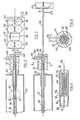
- Die Erfindung wird im folgenden an einem Ausführungsbeispiel an Hand der beigefügten Zeichnung erläutert. Es zeigt:
- Fig. 1
- eine schemaartige Gesamtansicht einer Vorrichtung zur erfindungsgemäßen Herstellung mit Schmierung versehener flexibler Kabelschutzrohre aus Kunststoff;
- Fig. 2
- eine Detailansicht teilweise im Schnitt der Anordnung in Fig. 1 im Bereich des Rohrspritzkopfes;
- Fig. 3
- die Anordnung gemäß Fig. 2, jedoch mit herausgezogenem Drahtführungsrohr;
- Fig. 4
- das Detail A in Fig. 2 in vergrößertem Maßstab;
- Fig. 5
- einen Schnitt nach Linie V-V in Fig. 3 durch den Kabelspritzkopf.
- Die in Fig. 1 schemaartig dargestellte Vorrichtung 10 zur Herstellung von Kabelschutzrohren mit Kabeleinziehdraht erhält den Draht 12 beispielsweise von einer Spule 14 und das Kunststoffmaterial für das Kabelschutzrohr 16 von einem Schneckenextruder 18 mit Extruder-Antriebsmotor 20. Vom Schneckenextruder 18 führt eine Leitung 22 in einen Rohrspritzkopf 24, welcher in den Figuren 2, 3 und 5 in weiteren Einzelheiten dargestellt ist. Der Rohrspritzkopf (Rohr-Offset-Spritzkopf) 24 erhält ferner den Draht 12 über eine Draht-Vorschubeinrichtung 26 zugeliefert. Ein Antriebsmotor der Draht-Vorschubeinrichtung 26 ist in Fig. 1 mit 28 bezeichnet. Das vom Rohrspritzkopf 24 abgegebene, noch nicht erhärtete Kabelschutzrohr 16 samt eingesetztem Draht 12 durchläuft eine Kalibrierhülse 30 in einer Stirnwand eines Kühlgehäuses 32. Im Kühlgehäuse 32 befinden sich in nicht dargestellter Weise eine Reihe von Abkühlbecken zur Abkühlung des Kabelschutzrohrs auf Raumtemperatur. Das abgekühlte Kabelschutzrohr wird mittels eines nicht dargestellten Bedruckungsgeräts, beispielsweise mit einer Kabelkennzeichnung, bedruckt. Es schließt sich ein in Fig. 1 wiederum dargestelltes Tastrad 34 an als Teil eines digitalen Meßwertaufnehmers 36 zur Messung der Rohrextrusionsgeschwindigkeit VR. Es folgt eine Rohr-Vorschubeinrichtung (Abzug) 38, welche auf die Rohrextrusionsgeschwindigkeit VR eingestellt ist. Das fertige Kabelschutzrohr wird auf eine Aufwickelspule 40 aufgewickelt, welche von einem Motor 42 angetrieben ist. Der Regelung der Drehgeschwindigkeit des Motors 42 dient eine Durchhang-Steuerung welche durch eine sog. Tänzerrolle 44 verwirklicht sein kann. Die Rolle 44 ist an einem Schwenkhebel 46 gelagert, wobei der Schwenkwinkel von einer Winkelmeßeinheit 48 gemessen wird.
- Eine durch einen Block 50 symbolisierte Auswerteschaltung steuert die Vorrichtung 10. Sie ist hierzu über entsprechende, strichliert angedeutete Leitungen sowohl mit den Motoren 20,28 und 42 verbunden als auch mit der Winkelmeßeinheit 48 und der Geschwindigkeits-Meßeinheit 36, insbesondere mit einem digitalen Meßwertaufnehmer 52 in Form beispielsweise eines optischen Abtastkopfes, welcher ein Strichraster des Rades 34 abtastet. Hierzu kann der Meßwertaufnehmer 52 an einen das Rad 34 halternden in Richtung auf das Rohr 16 vorgespannten (Zugfeder 54 am anderen Hebelarm) angebrachten Doppelarmhebel 56 angebracht sein. Zur Messung der Draht-Vorschubgeschwindigkeit VD ist die Auswerteschaltung 50 ferner mit der Drahtvorschubeinrichtung 26 verbunden, insbesondere mit einen Drehgeschwindigkeitsmesser an einer Druckrolle 58 der aus insgesamt 4 Druckrollen-Paaren aufgebeuten Draht-Vorschubeinrichtung 26.
- Die Auswerteschaltung 50 regelt nun die Draht-Vorschubgeschwindigkeit VD durch entsprechende Ansteuerung des Motors 28 derart, daß die Differenz zwischen der Drahtvorschubgeschwindigkeit VD und der Rohrextrusionsgeschwindigkeit VR verschwindet. Die Auswerteschaltung 50 kann eine Anzeige, insbesondere Digitalanzeige 60, aufweisen, um den Ist-Wert der Draht-Vorschubgeschwindigkeit anzuzeigen und ggf. die effektive Draht- und Rohrlänge, um die ggf. automatische Herstellung von Chargen mit unterschiedlicher Rohrlänge zu ermöglichen. Zur Messung der effektiven Rohrlänge kann es genügen, wenn man einen Impulszähler 62 an den digitalen Meßwertaufnehmer 52 anschließt, da die aufgezählten Impulse zur jeweiligen Rohrlänge proportional sind.
- In Fig. 1 erkennt man schließlich noch ein in den Figuren 2 bis 5 detaillierter dargestelltes Drahtführungsrohr 66, mit einem gabelförmigen Anschlußrohr 68. Das Drahtführungsrohr 66 ist gemäß den Fig. 4 und 5 doppelwandig ausgebildet, mit einer äußeren Rohrwand 70 und einer inneren Rohrwand 72. In den zwischen den beiden Wänden 70 und 72 gebildeten Ringraum 74 mündet das Anschlußrohr 68 ein. Der eine Gabelschenkel 76 des Anschlußrohrs 68 ist mit einem Gleitmittel-Vorratsbehälter 78 verbunden, und zwar über eine Leitung 80. In der Leitung 80 befindet sich eine Zuführpumpe 82 sowie ggf. ein Druckmesser 84. Die Pumpe 82 ist über eine Steuerleitung mit der Auswerteschaltung 50 verbunden, so daß die Gleitmittel-Zufuhr in den Ringraum 74 des Drahtführungsrohrs 70 durch die Auswerteschaltung 50 automatisch steuerbar ist. Als Gleitmittel kommt Mineralöl, Silikonöl, Glycerin, Wachs oder dergl. in Frage. An den anderen Gabelschenkel 86 des Anschlußrohres 68 ist eine Druckluftleitung 88 angeschlossen, welche in einem Druckluftmotor 90 endet. Dieser Druckluftmotor 90 ist wiederum mit der Auswerteschaltung 50 zur Steuerung der Vorrichtung 10 verbunden. Durch das Anschlußrohr 68 am in den Fig. 1 bis 4 rechten Ende des Drahtführungsrohrs 66 kann also im vorgegebenen Verhältnis Druckluft und Gleitmittel in den Ringraum 74 gepreßt werden, um dann durch Gleitmittel-Spritzdüsen 92 am in den Fig. 1 bis 4 linken Ende des Drahtführungsrohre 66 hindurch sowohl auf die Rohrinnenfläche 94 als auch auf den Umfang des Drahtes 12 gesprüht zu werden.
- Die Spritzdüsen 92 können beispielsweise dadurch gebildet werden, daß man die am Rohrende zusammengebogenen und miteinander dicht verbundenen, insbesondere verschweißten, Wände 70 und 72 dort mit axialen Bohrungen versieht.
- Das Drahtführungsrohr 66 ist in Richtung seiner Rohrachse 96 verschiebbar gelagert, und zwar zwischen einer in Fig. 2 dargestellten, am weitesten links liegenden Arbeitsposition und einer am weitesten rechts liegenden Rückzugsposition gemäß Fig. 3. In der Arbeitsposition befindet sich das linke Rohrende in einem derart großen Abstand vom Spritzkopf 24, daß das vom Rohrspritzkopf 24 erzeugte und bis in den Bereich des Rohrendes 96 gelangte Kabelschutzrohrmaterial bereits teilweise verfestigt ist. Der innerhalb der inneren Wand 72 des Drahtführungsrohrs 66 geführte, im Idealfall konzentrisch zur Rohrachse verlaufende Draht 12, darf folglich anschließend an das Rohrende 96 ohne weiteres die Rohrinnenfläche 94 berühren, ohne daß befürchtet werden muß, daß der Draht 12 an der Rohrinnenfläche 94 festklebt, oder gar in die Rohrwand eindringt. Während das Kabelschutzrohr 16 also in Richtung A der Fig. 2 (von rechts nach links) mit der Rohrextrusionsgeschwindigkeit VR am Rohrende 96 vorbeibewegt wird, wird die Rohrinnenfläche 94 mit Gleitmittel besprüht, dementsprechend auch der in der gleichen Richtung und möglichst mit derselben Geschwindigkeit sich bewegende Draht 12.
- Für die richtige Draht-Vorschubgeschwindigkeit VD sorgt die bereits erwähnte Draht-Vorschubeinrichtung 26, welche gemäß Fig. 1 und 2 aus 4 Druckrollen-Paaren 98 besteht sowie einer Vorgelegewelle 100. Man erkennt ferner Einstellschrauben 102 für die gegenseitige Andruckkraft der Druckrollen-Paare 98. Um ein Richten des Drahtes in zwei zueinander senkrechten Richtungen zu erreichen, ist beispielsweise eines der 4 Druckrollen-Paare um 90° gegenüber den anderen verdreht angeordnet.
- Der grundlegende Aufbau des Rohrspritzkopfs 24 geht aus den Fig. 2,3 und 5 hervor. Ein zur Rohrachse 94 koaxialer zylindrischer Grundkörper 104 weist eine durchgehende Axialbohrung 106 auf, deren Durchmesser im wesentlichen dem Außendurchmesser des Kabelschutzrohres 16 entspricht. Ein an den Schneckenextruder 18 gemäß Fig. 1 angeschlossener Zuführstutzen 108 des Grundkörpers 104 ist mit einer in die Bohrung 106 radial einmündenden Zuführbohrung 110 versehen, durch welche das plastifizierte Kunststoffmaterial in die Bohrung 106 transportiert wird. Ein in den Figuren mit einer Kreuz-Schraffur versehener, hülsenförmiger Spritzdorn 112 durchsetzt die Bohrung 106 über ihre gesamte Länge und ist in einer entsprechend dimensionierten Aufnahmebohrung 114 einer am Grundkörper 24 befestigten Abschlußplatte 116 gelagert. Der Außendurchmesser des Spritzdorns 112 entspricht im wesentlichen dem Innendurchmesser des herzustellenden Kabelschutzrohres 16. Auf diese Weise wird ein an den Kanal 110 angeschlossener Ringraum 118 zwischen dem Innenumfang der Bohrung 106 und dem Außenumfang des Dorns 112 gebildet, welcher dem Kabelschutzrohr-Querschnitt entspricht. Durch Zuführen von plastifiziertem Kunststoffmaterial in diesen Raum unter Druck durch die Leitung 110 erreicht man, daß am in den Fig. 2 und 3 linken Ende der Bohrung 106 das noch weiche Kunststoffmaterial in Rohrform austritt. In der sich anschließenden Kalibrierhülse 30 wird der Außendurchmesser des Rohres genau auf das gewünschte Maß gebracht. Dabei tritt der Draht 12 in das in Fig. 2 rechte Ende des Drahtführungsrohrs 66 ein. An diesem Ende sind die beiden Wände 70 und 72 miteinander abdichtend verbunden, insbesondere durch Verschweißen, so daß der Ringraum 74 gemäß Fig. 1 allseits geschlossen ist, bis auf die Düsen 92 am gegenüberliegenden Ende und auf das gabelförmige, in den Ringraum 74 einmündende Anschlußrohr 68.
- Wie die Fig. 2 und 5 zeigen, entspricht der Innendurchmesser des hülsenförmigen Spritzdorns 112 gerade dem Außendurchmesser des Drahtführungsrohrs 66, so daß das Drahtführungsrohr 66 von der Hülse 112 angenähert koaxial zum Kabelschutzrohr 16 gehalten wird. Der sich an den Rohrspritzkopf 24 nach links bis zum Rohrende 96 anschließende Rohrabschnitt hat daher stets ausreichenden Abstand zum Kabelschutzrohr 16.
- Dieser Abstand ist jedoch beim Anfahren der Vorrichtung 10 nicht gewährleistet, da das Vorlaufende des im Spritzkopf 24 hergestellten Kabelschutzrohres nicht formstabil ist. Auch kann es anfänglich an der Kalibrierhülse 30 zu einem Materialstau kommen. Beim Anfahren der Vorrichtung 10 wird folglich das Drahtführungsrohr 66 in seine Rückzugsstellung gemäß Fig. 3 zurückgezogen, wobei ggf. auch die Drahtvorschubeinrichtung 26 entsprechend zurückzuziehen ist. Sobald ein gut kalibriertes Kabelschutzrohr vorliegt, wird das Drahtführungsrohr 66 durch das rechtsseitige Ende des Rohrspritzkopfes 24 bis in die Arbeitsposition gemäß Fig. 2 vorgeschoben. Dann wird im Schnellgang der Draht-Vorschubeinrichtung 26 von dieser der Draht 12 in das Kabelschutzrohr 16 eingeschoben, bis er das freie Rohrende erreicht hat. Dann erst wird die vorstehend beschriebene Auswerteschaltung 50 in Gang gesetzt, welche die Draht-Vorschubgeschwindigkeit VD an die Rohrextrusionsgeschwindigkeit VR anpaßt.
- Aufgrund der gleichen Geschwindigkeiten ergibt sich auch exakt die gleiche Länge von Kabelschutzrohr 16 und innerhalb des Kabelschutzrohrs verlaufendem Einziehdrat 12 (in gestrecktem Zustand des Kabelschutzrohrs 16). Von den elastischen Eigenschaften des Kabelschutzrohres beim Aufwickeln auf die Trommel 40 gemäß Fig. 1 abhängig, folgt der Draht 12 mehr oder weniger der Rohrachse des aufgewickelten Kabelschutzrohres.
- Das Kabelschutzrohr besteht vorzugsweise aus Hochdruck(High Density)-Polyethylen (HDPE). Da die einzuziehenden Kabel, insbesondere Lichtwellenleiter-Kabel, entweder mit Polyethylen (PE) oder Weich-Polyvinylchlorid (PVC) ummantelt sind, ergibt sich eine geringe Reibung zwischen Kabel und Rohrwandung beim Einziehen des Kabels aufgrund der Schmierung der Rohrinnenfläche 94 mit Gleitmittel. Da auch der Draht 12 mit Gleitmittel versehen ist, ist auch dessen Reibungskraftbeitrag beim Einziehen eines Kabels gering. Die ringförmig am Drahtführungsrohrende 96 vorgesehenen Sprühdüsen 92 versprühen einen weitgefächerten Schleier feinster Gleitmittel-Tröpfchen, die sich als Nebel auf die Rohrinnenfläche 94 und die Ziehdrahtoberfläche niederschlagen und so für gute Ausnützung des Gleitmittels sorgen. Das Material des Kabelschutzrohrs im Bereich des Rohrendes 96 ist zwar bereits teilweise verfestigt, jedoch noch heiß, so daß das aufgesprühte Gleitmittel haftet.
- Sämtliche Vorgänge des Herstellungsprozesses, nämlich die Extrusion des Kabelschutzrohres, das fortwährende Einschieben des Ziehdrahts, das Pumpen und Besprühen mit Gleitmittel, laufen kontinuierlich ab. Nach Beendigung des Herstellungsverfahrens werden der Schneckenextruder 18, die Draht-Vorschubeinrichtung 26 sowie die Pumpen 82,90 abgeschaltet, sodann die Draht-Vorschubeinrichtung 26 zurückgefahren und das Drahtführungsrohr doppelwandiges Stahlrohr) aus dem Kabelschutzrohr sowie dem Rohrspritzkopf (Offset-Kopf) herausgezogen.
- Erfindungsgemäß können Kabelschutzrohre mit über 1.000 m Länge ohne weiteres in einem Stück verlegt werden mit anschließendem Einziehen des Kabels.
Claims (4)
- Verfahren zur Schmierung flexibler Kabelschutzrohre aus Kunststoff, in welche bei der Kabelverlegung ein Kabel mittels Kabeleinziehdraht einziehbar ist, dadurch gekennzeichnet, daß man bereits bei der Kabelschutzrohrherstellung die Rohrinnenfläche mit Gleitmittel besprüht, und zwar in einem Bereich, in dem das aus dem Rohrspritzkopf tretende Material zwar bereits teilweise verfestigt, jedoch noch so heiß ist, daß das aufgesprühte Gleitmittel haftet.
- Verfahren nach Anspruch 1, dadurch gekennzeichnet, daß man als Gleitmittel ein Mineral-Öl, ein Silikon-Öl oder andere organische Flüssigkeiten verwendet, wie z.B. Glycerin.
- Verfahren nach Anspruch 2, dadurch gekennzeichnet, daß man als Gleitmittel organische Medien verwendet, wie z.B. Wachs, insbesondere Paraffin oder Olefin oder PTFE (Polytetrafluorethylen).
- Verfahren nach einem der Ansprüche 1 bis 3, dadurch gekennzeichnet, daß man das Gleitmittel, sei es unter Gaszufuhr (mit Treibgas) oder mit Flüssigkeitsdruck, versprüht.
Priority Applications (1)
| Application Number | Priority Date | Filing Date | Title |
|---|---|---|---|
| AT87116088T ATE68745T1 (de) | 1984-03-20 | 1985-03-19 | Verfahren und vorrichtung zur herstellung flexibler kabelschutzrohre mit kabeleinziehdraht. |
Applications Claiming Priority (2)
| Application Number | Priority Date | Filing Date | Title |
|---|---|---|---|
| BE0/212598A BE899205A (de) | 1984-03-20 | 1984-03-20 | Verfahren und vorrichtung zur herstellung flexibler kabelschutzrohre mit kabeleinziehdraht. |
| BE212598 | 1984-03-20 |
Related Parent Applications (1)
| Application Number | Title | Priority Date | Filing Date |
|---|---|---|---|
| EP85870040.4 Division | 1985-03-19 |
Publications (3)
| Publication Number | Publication Date |
|---|---|
| EP0274018A2 EP0274018A2 (de) | 1988-07-13 |
| EP0274018A3 EP0274018A3 (en) | 1988-08-31 |
| EP0274018B1 true EP0274018B1 (de) | 1991-10-23 |
Family
ID=3843739
Family Applications (2)
| Application Number | Title | Priority Date | Filing Date |
|---|---|---|---|
| EP87116088A Expired - Lifetime EP0274018B1 (de) | 1984-03-20 | 1985-03-19 | Verfahren und Vorrichtung zur Herstellung flexibler Kabelschutzrohre mit Kabeleinziehdraht |
| EP85870040A Expired - Lifetime EP0160632B2 (de) | 1984-03-20 | 1985-03-19 | Verfahren und Vorrichtung zur Herstellung flexibler Kabelschutzrohre mit Kabeleinziehdraht |
Family Applications After (1)
| Application Number | Title | Priority Date | Filing Date |
|---|---|---|---|
| EP85870040A Expired - Lifetime EP0160632B2 (de) | 1984-03-20 | 1985-03-19 | Verfahren und Vorrichtung zur Herstellung flexibler Kabelschutzrohre mit Kabeleinziehdraht |
Country Status (3)
| Country | Link |
|---|---|
| EP (2) | EP0274018B1 (de) |
| AT (2) | ATE43098T1 (de) |
| DE (2) | DE3570205D1 (de) |
Families Citing this family (9)
| Publication number | Priority date | Publication date | Assignee | Title |
|---|---|---|---|---|
| ATE77476T1 (de) * | 1987-04-13 | 1992-07-15 | Siemens Ag | Verfahren zur bestimmung des laengenunterschiedes zwischen lichtleitfaser und lichtleitaderhuelle. |
| GR880100782A (el) * | 1988-05-09 | 1990-03-12 | Cables De Lyon Geoffroy Delore | Μεθοδος χαλαρης επενδυσεως μιας οπτικης ινας και συσκευη για τηνεφαρμογη της μεθοδου αυτης. |
| FR2650922A1 (fr) * | 1989-08-08 | 1991-02-15 | Pecot Alain | Entraineurs intermediaires de cable a commande automatique |
| DE9000546U1 (de) * | 1990-01-19 | 1990-03-22 | Bast, Manfred, 84061 Ergoldsbach | Installationsrohr |
| FR2689698B1 (fr) * | 1992-04-03 | 1994-06-03 | Courant Ets Sa | Conduit isolant destine au passage d'un cable electrique ou similaire. |
| FR2691263A1 (fr) * | 1992-05-15 | 1993-11-19 | Filotex Sa | Procédé de fabrication d'un câble optique monovoie et procédé de fabrication d'un cordon spirale mixte, câble optique monovoie et cordon spirale mixte obtenus par ces procédés. |
| CN101295060B (zh) * | 2008-06-19 | 2010-04-07 | 湖北凯乐科技股份有限公司 | 管道复合光缆加工工艺 |
| NL2008847C2 (en) * | 2012-05-21 | 2013-11-25 | New Business Initiatives B V | Method for producing an assembly of a protective duct and an optical fibre cable arranged therein. |
| CN110441876B (zh) * | 2019-08-13 | 2021-02-05 | 安塞亿峰工贸有限责任公司 | 井下光缆保护器及保护方法 |
Family Cites Families (12)
| Publication number | Priority date | Publication date | Assignee | Title |
|---|---|---|---|---|
| US2644983A (en) * | 1950-06-29 | 1953-07-14 | Us Rubber Co | Tube extrusion |
| LU41916A1 (de) * | 1961-06-21 | 1962-08-20 | ||
| US3899384A (en) * | 1970-12-02 | 1975-08-12 | William F Kelly | Apparatus for manufacturing a tendon |
| DE2329266A1 (de) * | 1973-06-08 | 1975-01-02 | Kabel Metallwerke Ghh | Verfahren zur herstellung von strangfoermigem gut, beispielsweise elektrischen kabeln und leitungen |
| DE2353110A1 (de) * | 1973-10-23 | 1975-09-11 | Siemens Ag Oesterreich | Messeinrichtung zur bestimmung der wandstaerke von kunststoffummantelungen |
| GB1526777A (en) * | 1976-12-01 | 1978-09-27 | Pilkington Brothers Ltd | Method and apparatus for sheathing fibres |
| US4127370A (en) * | 1975-05-14 | 1978-11-28 | The Post Office | Apparatus for forming dielectric optical waveguides |
| FR2325061A1 (fr) * | 1975-09-19 | 1977-04-15 | Cables De Lyon Geoffroy Delore | Protection d'une fibre optique |
| FR2397934A1 (fr) * | 1977-07-22 | 1979-02-16 | Usinage Tubes Pour Electr | Dispositif d'introduction d'un fil dans une tete d'extrudeuse pour l'extrusion et la conformation d'un tube annele en matiere plastique |
| GB1561466A (en) * | 1978-02-16 | 1980-02-20 | Post Office | Coating of fibres |
| US4137623A (en) * | 1978-04-07 | 1979-02-06 | Taylor Industries, Inc. | Method and apparatus for dispensing fluid in a conduit |
| IT1162025B (it) * | 1978-10-09 | 1987-03-18 | Carboni Ivo | Tubo flessibile per il passaggio di cavi elettrici,con anima interna atta a permettere una rapida e sicura introduzione degli stessi |
-
1985
- 1985-03-19 DE DE8585870040T patent/DE3570205D1/de not_active Expired
- 1985-03-19 DE DE8787116088T patent/DE3584524D1/de not_active Expired - Lifetime
- 1985-03-19 EP EP87116088A patent/EP0274018B1/de not_active Expired - Lifetime
- 1985-03-19 EP EP85870040A patent/EP0160632B2/de not_active Expired - Lifetime
- 1985-03-19 AT AT85870040T patent/ATE43098T1/de not_active IP Right Cessation
- 1985-03-19 AT AT87116088T patent/ATE68745T1/de not_active IP Right Cessation
Also Published As
| Publication number | Publication date |
|---|---|
| ATE68745T1 (de) | 1991-11-15 |
| EP0274018A2 (de) | 1988-07-13 |
| EP0160632B2 (de) | 1995-09-13 |
| DE3570205D1 (en) | 1989-06-22 |
| EP0274018A3 (en) | 1988-08-31 |
| ATE43098T1 (de) | 1989-06-15 |
| DE3584524D1 (de) | 1991-11-28 |
| EP0160632B1 (de) | 1989-05-17 |
| EP0160632A1 (de) | 1985-11-06 |
Similar Documents
| Publication | Publication Date | Title |
|---|---|---|
| DE3876679T2 (de) | Verfahren zum herstellen eines kabelartigen verbundkoerpers aus kunststoff. | |
| DE69916381T2 (de) | Elektrische Leitung und Verfahren und Vorrichtung zum Konfektionieren derselben | |
| EP0159307B1 (de) | Verfahren zum Aufbringen eines elektrisch leitfähigen Drahtes auf ein Kabelschutzrohr | |
| DE2744369C2 (de) | Verfahren zum kontinuierlichen Umhüllen eines Rohres mit Schaum | |
| DE3308482C2 (de) | Flexibler Rohrverbund und Herstellungsverfahren hierzu | |
| DE2735571C3 (de) | Vorrichtung zum Auftragen einer ringwulstförmige Verdickungen aufweisenden Schicht auf ein Stahlrohr | |
| DE69129199T2 (de) | Verfahren und oder Vorrichtung zur Beschichtung faserförmigen Materials | |
| EP1084774B1 (de) | Verfahren zur kontinuierlichen Herstellung längsnahtgeschweisster und gewellter Metallrohre und Vorrichtung zur Durchführung des Verfahrens | |
| EP0160632B1 (de) | Verfahren und Vorrichtung zur Herstellung flexibler Kabelschutzrohre mit Kabeleinziehdraht | |
| DE69737989T2 (de) | Verfahren zur Herstellung eines Lichtwellenleiterkabels | |
| WO2021180842A1 (de) | Thermoplastischer schlauch sowie eine vorrichtung und ein verfahren zur herstellung eines solchen | |
| DE3027743C2 (de) | ||
| EP1304176A2 (de) | Verfahren zur kontinuierlichen Herstellung eines längsnahtgeschweissten Metallrohres | |
| DE69508105T2 (de) | Kunststoffrohr, extrusionsdüse und verfahren zur herstellung solche kunststoffröhren | |
| DE2849814C2 (de) | Verfahren und Vorrichtung zum Beschichten eines eine Schweißnaht aufweisenden Stahlrohres mit einer Mantelschicht aus thermoplastischem Kunststoff | |
| EP0233439B1 (de) | Verfahren und Vorrichtung zur kontinuierlichen Herstellung faserverstärkter Kunststoff-Hohlprofile und Kunststoff-Hohlprofil | |
| DE2727318C2 (de) | Arbeitsverfahren sowie Vorrichtung zum Herstellen eines verstärkten Schlauches | |
| BE899205A (de) | Verfahren und vorrichtung zur herstellung flexibler kabelschutzrohre mit kabeleinziehdraht. | |
| DE4210633C2 (de) | Verfahren zur Erzeugung von Lichtwellenleiter-Überlängen und Vorrichtung zur Durchführung des Verfahrens | |
| DE3618810C2 (de) | ||
| EP0823295B1 (de) | Verfahren zum Ummanteln eines Kunststoffrohres mit einem Metallband und Schweissstation zum Verschweissen der einander überlappenden Längsränder des Metallbandes | |
| DE2613782A1 (de) | Verfahren und vorrichtung zur herstellung armierter druckrohre aus thermoplastischen kunststoffen | |
| DE4400824A1 (de) | Verfahren und Vorrichtung zur Längenmessung eines langgestreckten Übertragungselements | |
| DE4327215C1 (de) | Vorrichtung zur Prüfung und/oder Reparatur von Kanälen | |
| EP1640652A2 (de) | Thermisch isoliertes, flexibles Leitungsrohr und Verfahren zur und Vorrichtung für die Herstellung eines Leitungsrohrs |
Legal Events
| Date | Code | Title | Description |
|---|---|---|---|
| PUAI | Public reference made under article 153(3) epc to a published international application that has entered the european phase |
Free format text: ORIGINAL CODE: 0009012 |
|
| 17P | Request for examination filed |
Effective date: 19871102 |
|
| AC | Divisional application: reference to earlier application |
Ref document number: 160632 Country of ref document: EP |
|
| AK | Designated contracting states |
Kind code of ref document: A2 Designated state(s): AT CH DE FR GB IT LI LU NL SE |
|
| PUAL | Search report despatched |
Free format text: ORIGINAL CODE: 0009013 |
|
| ITCL | It: translation for ep claims filed |
Representative=s name: BARZANO' E ZANARDO MILANO S.P.A. |
|
| AK | Designated contracting states |
Kind code of ref document: A3 Designated state(s): AT CH DE FR GB IT LI LU NL SE |
|
| GBC | Gb: translation of claims filed (gb section 78(7)/1977) | ||
| TCNL | Nl: translation of patent claims filed | ||
| EL | Fr: translation of claims filed | ||
| 17Q | First examination report despatched |
Effective date: 19890619 |
|
| GRAA | (expected) grant |
Free format text: ORIGINAL CODE: 0009210 |
|
| AC | Divisional application: reference to earlier application |
Ref document number: 160632 Country of ref document: EP |
|
| AK | Designated contracting states |
Kind code of ref document: B1 Designated state(s): AT CH DE FR GB IT LI LU NL SE |
|
| PG25 | Lapsed in a contracting state [announced via postgrant information from national office to epo] |
Ref country code: IT Free format text: LAPSE BECAUSE OF FAILURE TO SUBMIT A TRANSLATION OF THE DESCRIPTION OR TO PAY THE FEE WITHIN THE PRE;WARNING: LAPSES OF ITALIAN PATENTS WITH EFFECTIVE DATE BEFORE 2007 MAY HAVE OCCURRED AT ANY TIME BEFORE 2007. THE CORRECT EFFECTIVE DATE MAY BE DIFFERENT FROM THE ONE RECORDED.SCRIBED TIME-LIMIT Effective date: 19911023 Ref country code: SE Effective date: 19911023 |
|
| REF | Corresponds to: |
Ref document number: 68745 Country of ref document: AT Date of ref document: 19911115 Kind code of ref document: T |
|
| ET | Fr: translation filed | ||
| REF | Corresponds to: |
Ref document number: 3584524 Country of ref document: DE Date of ref document: 19911128 |
|
| GBT | Gb: translation of ep patent filed (gb section 77(6)(a)/1977) | ||
| PLBE | No opposition filed within time limit |
Free format text: ORIGINAL CODE: 0009261 |
|
| STAA | Information on the status of an ep patent application or granted ep patent |
Free format text: STATUS: NO OPPOSITION FILED WITHIN TIME LIMIT |
|
| 26N | No opposition filed | ||
| EPTA | Lu: last paid annual fee | ||
| PGFP | Annual fee paid to national office [announced via postgrant information from national office to epo] |
Ref country code: LU Payment date: 19960301 Year of fee payment: 12 |
|
| PGFP | Annual fee paid to national office [announced via postgrant information from national office to epo] |
Ref country code: GB Payment date: 19960308 Year of fee payment: 12 |
|
| PGFP | Annual fee paid to national office [announced via postgrant information from national office to epo] |
Ref country code: FR Payment date: 19960321 Year of fee payment: 12 |
|
| PGFP | Annual fee paid to national office [announced via postgrant information from national office to epo] |
Ref country code: AT Payment date: 19960327 Year of fee payment: 12 |
|
| PGFP | Annual fee paid to national office [announced via postgrant information from national office to epo] |
Ref country code: CH Payment date: 19960328 Year of fee payment: 12 |
|
| PG25 | Lapsed in a contracting state [announced via postgrant information from national office to epo] |
Ref country code: GB Effective date: 19970319 Ref country code: AT Effective date: 19970319 Ref country code: LU Free format text: LAPSE BECAUSE OF NON-PAYMENT OF DUE FEES Effective date: 19970319 |
|
| PG25 | Lapsed in a contracting state [announced via postgrant information from national office to epo] |
Ref country code: LI Effective date: 19970331 Ref country code: CH Effective date: 19970331 |
|
| GBPC | Gb: european patent ceased through non-payment of renewal fee |
Effective date: 19970319 |
|
| REG | Reference to a national code |
Ref country code: CH Ref legal event code: PL |
|
| PG25 | Lapsed in a contracting state [announced via postgrant information from national office to epo] |
Ref country code: FR Free format text: LAPSE BECAUSE OF NON-PAYMENT OF DUE FEES Effective date: 19971128 |
|
| REG | Reference to a national code |
Ref country code: FR Ref legal event code: ST |
|
| PGFP | Annual fee paid to national office [announced via postgrant information from national office to epo] |
Ref country code: NL Payment date: 19990331 Year of fee payment: 15 |
|
| PG25 | Lapsed in a contracting state [announced via postgrant information from national office to epo] |
Ref country code: NL Free format text: LAPSE BECAUSE OF NON-PAYMENT OF DUE FEES Effective date: 20001001 |
|
| NLV4 | Nl: lapsed or anulled due to non-payment of the annual fee |
Effective date: 20001001 |
|
| PGFP | Annual fee paid to national office [announced via postgrant information from national office to epo] |
Ref country code: DE Payment date: 20020415 Year of fee payment: 18 |
|
| PG25 | Lapsed in a contracting state [announced via postgrant information from national office to epo] |
Ref country code: DE Free format text: LAPSE BECAUSE OF NON-PAYMENT OF DUE FEES Effective date: 20031001 |